Site: Danish | English
Moto Guzzi frame numbers - is your bike what's its supposed to be ?
Gasoline - will a Moto Guzzi run on unleaded gasoline ?
Expected mileage of parts - a VERY rough guide to the expected lifetime of various parts.
Tuning - information on what will make it go faster.
Brake caliper overhaul - how-to guide.
Wiring - more warnings than help, I guess.
Wiring charts - see or download here.
Carburetor - Dell Orto Manual online
Carburetor - drawings, charts, and a how-to guide.
Gearing - Contains a nice utility for calculating gear ratios,
Special tools - see why you'll need them.
O-rings, seals, and gaskets - what you need to repair.
Technical : The complex stuff - exciting but heavy reading, take your time.
Please contact Gregory Bender with any questions, corrections, or suggestions for improvement.
Technical
Carburetor - drawings, charts, and a how-to guide.
It's not that hard - and yet! Most people understands the basic function of the carburetor, but it's a long hard road to learn to adjust it properly.
If your bike is in fairly standard trim start from the factory settings as found below. From here you can experiment with jets and needles. Its quite cheap on the Dell Orto's.
Note that all the basic stuff like ignition timing, valve adjustment and synchronization of the two carbs must be properly done before you start playing with the jets. Otherwise its just a waste of time.
If you don't feel like using a lot of time to learn this, I suggest you pay a qualified mechanic to do it (look carefully), and then stick to emptying the float chambers and do the synchronization once in a while.
Dell Orto's are very easy to work on. The necessary information can be found on these pages, but remember: YOU'RE RESPONSIBLE FOR WHAT YOU'RE DOING.
Factory settings
See how it was jetted from the factory. Usually, older bikes have had a number of weird owners with weird ideas about how to jet a bike. So start by checking the jets and needles.
| MC | Carburetor | Idle jet | Main jet | needle | Clip position (From top) | Needle jet | Slide |
|---|---|---|---|---|---|---|---|
| V7 Sport, 750S, S3, 850T | VHB 30 | 50 | 142 | V-9 | 2 | 265 | 40 |
| T3, T4 | VHB 30 | 50 | 120 | V-9 | 2 | 265 | 40 |
| Le Mans 1 | PHF 36 | 60 | 135 | K-5 | 2 | 265 | 60/1 |
| Le Mans 2 | PHF 36 | 60 | 140 | K-5 | 2 | 265 | 60/1 |
| Le Mans 3 | PHF 36 | 50 | 115 | K-18 | 3 | 268 | 60/3 |
| Le Mans 4 | PHM 40 | 57 | 145 | K-19 | 3 | 268 | 60/5 |
| Le Mans 5, Big valve California 3 | PHM 40 | 57 | 145 | K-19 | 3 | 268 | 60/5 |
| California 2, SP2 | VHB 30 | 50 | 125 | V-9 | 2 | 265 | 40 |
| T5, CX100, 1000SP, Convert, G5 | VHB 30 | 50 | 130 | V-9 | 2 | 265 | 40 |
| California 2, SP2, T5, CX100, 1000SP, Convert, G5 | PHF 30 | 50 | 125 | K-23 | 3 | 264 | 50/3 |
| California 3, Mille GT | PHF 30 | 50 | 130 | K-23 | 3 | 264 | 50/3 |
| 1000S | PHM 40 | 57 | 145 | K-19 | 3 | 266 | 60/5 |
| Strada 1000, 1000S, SP3, California 3 | PHF 36 | 50 | 130 | K-18 | 3 | 268 | 60/3 |
| California 1100 | PHF 36 | 50 | 130 | K-18 | 2 | 266 | 60/3 |
| Sport 1100 | PHM 40 | 57 | 152 | K-18 | 3 | 266 | 60/5 |
Note that LM3 uses a special version of the PHF36 with a different atomizer that allows for the use of smaller main jets.
"Explosion" drawing
Including spare parts numbers
| Diag No. | Part No. | Description | Sizes/options available |
|---|---|---|---|
| 1 | 8639 | Slide | 401,501,503,505,601,603 & 605 |
| 2 | 8530 | Needle | K1 to K95 |
| 3 | 8540 | Atomizer AB | 258,60,62,64,65,66,68,70,72,75,78,80,90 & 300 |
| 3 | 12599 | Atomizer DR | 266,268,270 & 272. |
| 4 | 9980 | Idle emulsion tube | Not fitted to all models |
| 5 | 6413 | Main Jet | 56 to 330, in steps of 1,2 & 3. Please ask. |
| 6 | 1486 | Idle jet (short) | 30 to 198, in steps of 1,2 & 3. Please ask |
| 7 | 7746 | Choke jet | 45,50,55,60,65,70,75,80,85 & 90 |
| 8 | 7851 | Pump jet | 30,33,35,38,40,42,45,48,50,55,60,65,70,75,90,150 |
| 9 | 10375 | Float needle valve | 150, 170, 200, 225 |
| 9 | 8649 | Float needle valve | 250, 270, 300, 350, 400 |
| 10 | 7450 | Float | .1, .2 & .3 |
| 11 | 6429 | Top cover screw | |
| 12 | 1581 | Spring washer | |
| 13 | 8826 | Top paper gasket | |
| 14 | 8542 | Screw | |
| 15 | 11779 | Slide rod | |
| 16 | 11798 | Top casting | |
| 17 | 8726 | Spindle seal | |
| 18 | 8727 | Spindle seal cover | |
| 19 | 8535 | Pump arm pin | Metal top |
| 19 | 10924 | Pump arm pin | Plastic top |
| 20 | 9383 | Spring | |
| 21 | 11777 | Slide rod | |
| 22 | 10451 | circlip | |
| 23 | 8941 | Throttle lever | |
| 24 | 11773 | Needle washer | |
| 25 | 9596 | Needle circlip | |
| 26 | 8633 | Top cover O ring | |
| 27 | 3718 | Washer | |
| 28 | 11776 | Slide rod | |
| 29 | 11774 | Spring guide | |
| 30 | 11786 | External return spring | |
| 31 | 11775 | Spring guide | |
| 32 | 11787 | Throttle cable support | |
| 33 | 6435 | Screw | |
| 34 | 4957 | Spring washer | |
| 35 | 11788 | Left hand throttle support | |
| 36 | 8825 | Dome top cover | |
| 37 | 9042 | Allen screw | |
| 38 | 5011 | Spring washer | |
| 39 | 8830 | Cable arm | |
| 40 | 8725 | Spindle seal | |
| 41 | 10069 | Slide rod guide | |
| 42 | 7415 | Pump arm spring | |
| 43 | 8426 | Pump arm | |
| 44 | 3698 | 90 Degree cable elbow | |
| 44 | 3600 | 70 Degree cable elbow | |
| 44 | 9330 | 40 Degree cable elbow | |
| 45 | 1692 | Adjuster locknut (for 1481) | |
| 46 | 1481 | Cable adjuster | |
| 47 | 1476 | Rubber cable cap | |
| 48 | 1104 | Cable adjuster | |
| 49 | 1691 | Adjuster locknut (for 1104) | |
| 50 | 3128 | Choke support | |
| 51 | 3133 | Choke return spring | |
| 52 | 3238 | Choke piston | |
| 53 | 11650 | Long choke body screw | |
| 54 | 8711 | Choke body screw | |
| 55 | 8887 | Choke housing | |
| 56 | 8888 | Choke housing gasket | |
| 57 | 11651 | Choke housing spacer (LM) | |
| 57 | 7749 | Mixture screw "standard" | |
| 58 | 11084 | Mixture screw "Guzzi" | |
| 59 | 9336 | Mixture screw spring | |
| 60 | 8260 | Mixture screw washer | |
| 61 | 8678 | Mixture screw O ring | |
| 62 | 10747 | Pump jet holder | |
| 63 | 6426 | Pump jet holder fibre washer | |
| 64 | 6173 | Pump jet O ring | |
| 65 | 7673 | Throttle stop screw | |
| 66 | 4670 | Throttle stop screw spring | |
| 67 | 4650 | Washer | |
| 68 | 7540 | O ring | |
| 69 | 10800 | Pump non return valve | |
| 70 | 8556 | Pump cover | |
| 71 | 8598 | Adjuster screw O ring | |
| 72 | 8599 | Pump adjuster locknut | |
| 73 | 8539 | Pump adjustment screw | |
| 74 | 8428 | Screw | |
| 75 | 7626 | Diaphagm spring | |
| 76 | 8555 | Pump diaphragm | |
| 77 | 9278 | Diaphragm gasket | |
| 78 | 8885 | Main jet holder | |
| 79 | 11785 | Operating lever, RH | |
| 80 | 11799 | Top casting | |
| 81 | 6109 | Fuel banjo filter | |
| 82 | 9250 | Plastic fuel union | |
| 82 | 6273 | Metal fuel union | |
| 82 | 7890 | Double fuel union | |
| 83 | 4568 | Fuel union bolt | |
| 84 | 8557 | Non return valve | |
| 85 | 6288 | Needle valve fibre washer | |
| 86 | 7451 | Float bowl O ring | |
| 87 | 7346 | Float pivot pin | |
| 88 | 10557 | Float bowl | |
| 89 | 4057 | Float bowl nut seal | |
| 90 | 10238 | Float bowl nut | |
| 91 | 52560 | PHM N, cranked top | |
| 91 | 52520 | PHM A,B,N,V gasket set | |
| 91 | 52544 | PHM..H,L,M,P,R,T,S,Z gasket set | |
| 91 | 52545 | PHM A,B,N,V gasket set | |
| 92 | 4052 | Fuel union seal | |
| 93 | 9573 | Short plastic trumpet | |
| 94 | 8673 | Long trumpet with wire gauze | |
| 95 | 8128 | Clamp nut | |
| 96 | 8127 | Clamp bolt | |
| 97 | 8528 | Clamp | |
| 98 | 8596 | PHM38 R90S mounting sleeve | |
| 99 | 10923 | Plastic top | |
| 100 | 8550 | Slide spring 0.7kg/70mm | |
| 100 | 8532 | Slide spring 1.1kg/70mm | |
| 100 | 9389 | Slide spring 1.4kg/70mm | |
| 101 | 8525 | Needle clip |
Numbers on jets and needles
Do the tiny numbers have a purpose ?
Jets:
Its quite simple - the number on the jet tells you the size of the hole in the jet, measured in 1/100 mm's. So a 60 jet has a bore of 0,6mm and a 268 needle jet is 2,68mm inside. Note that the thread and the external size of the jet depends of its location in the carburetor. So when you order a jet, you'll have to state if you want a main jet, idle jet, etc, AND the size of the jet.
Needle:
This is a bit more tricky. There's so many significant dimensions on a carburetor needle that it wouldn't make sense to identify the needle with a number referring to a single dimension on the needle. So they have apparently random numbers, and to see the differences between two needles its necessary to use the chart below.
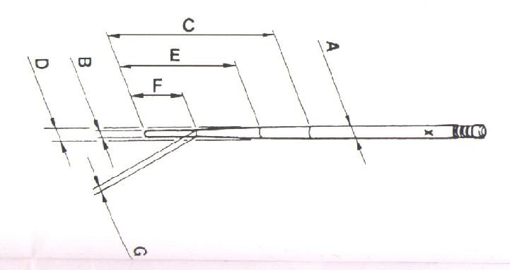
| Type | Ø-A | Ø-B | C | Ø-D | E | F | G |
|---|---|---|---|---|---|---|---|
| K-1 | 2,45 | 1,75 | 37 | - | - | - | - |
| K-2 | 2,45 | 1,75 | 42 | - | - | - | - |
| K-3 | 2,50 | 1,5 | 39 | - | - | - | - |
| K-4 | 2,45 | 1,5 | 39 | - | - | - | - |
| K-5 | 2,45 | 1,5 | 37 | - | - | - | - |
| K-6 | 2,45 | 1,75 | 39 | - | - | - | - |
| K-7 | 2,45 | 1,25 | 39 | - | - | - | - |
| K-8 | 2,50 | 1,5 | 37 | - | - | - | - |
| K-9 | 2,45 | 1,5 | 42 | - | - | - | - |
| K-11 | 2,50 | 1,25 | 39 | - | - | - | - |
| K-12 | 2,48 | 1,75 | 32 | - | - | - | - |
| K-13 | 2,45 | 1,25 | 38 | - | - | - | - |
| K-14 | 2,48 | 1,75 | 33 | - | - | - | - |
| K-15 | 2,50 | 0,6 | 26 | - | - | - | - |
| K-16 | 2,50 | 1,75 | 39 | - | - | - | - |
| K-17 | 2,42 | 1,75 | 40 | - | - | - | - |
| K-18 | 2,50 | 1,4 | 38 | - | - | - | - |
| K-19 | 2,50 | 1,4 | 40 | - | - | - | - |
| K-20 | 2,50 | 1,4 | 42 | - | - | - | - |
| K-21 | 2,50 | 1,8 | 38 | - | - | - | - |
| K-22 | 2,50 | 1,8 | 40 | - | - | - | - |
| K-23 | 2,50 | 1,8 | 42 | - | - | - | - |
| K-24 | 2,50 | 1,2 | 38 | 2,13 | 18 | - | - |
| K-25 | 2,50 | 1 | 36 | 2,15 | 18 | - | - |
| K-27 | 2,50 | 1,8 | 44 | - | - | - | - |
| K-28 | 2,50 | 1,8 | 41 | - | - | - | - |
| K-29 | 2,45 | 1,25 | 42 | - | - | - | - |
| K-30 | 2,50 | 1,4 | 36 | 2,15 | 18 | - | - |
| K-32 | 2,48 | 1,7 | 44 | - | - | - | - |
| K-33 | 2,50 | 1,8 | 44 | - | - | - | - |
| K-34 | 2,50 | 1,4 | 40 | 2,11 | 18 | - | - |
| K-35 | 2,50 | 1,4 | 43 | - | - | - | - |
| K-36 | 2,50 | 1,4 | 38 | 2,17 | 20 | - | - |
| K-37 | 2,50 | 1,4 | 39 | 2,12 | 18 | - | - |
| K-38 | 2,50 | 1,4 | 38 | 2,13 | 18 | - | - |
| K-39 | 2,48 | 1,45 | 36 | 2,28 | 26 | - | - |
| K-40 | 2,50 | 1,4 | 40 | 2,18 | 22 | - | - |
| K-41 | 2,50 | 1,4 | 40 | 2,14 | 22 | - | - |
| K-42 | 2,50 | 1,4 | 38 | 2,16 | 22 | - | - |
| K-43 | 2,50 | 1,4 | 42 | 2,16 | 26 | - | - |
| K-44 | 2,50 | 1,4 | 39 | 2,06 | 20 | - | - |
| K-45 | 2,48 | 1,3 | 36 | 2,28 | 26 | - | - |
| K-46 | 2,50 | 1,4 | 40 | 2,15 | 20 | - | - |
| K-48 | 2,48 | 1,6 | 36 | 2,25 | 25 | 11 | 1,60 |
| K-49 | 2,50 | 1,4 | 39 | 2,20 | 26 | - | - |
| K-50 | 2,50 | 1,4 | 39 | 2,27 | 26 | - | - |
| K-52 | 2,50 | 1,6 | 36 | 2,25 | 25 | 11 | 1,60 |
| K-53 | 2,52 | 1,6 | 36 | 2,25 | 25 | 11 | 1,60 |
| K-54 | 2,48 | 1,5 | 40 | 2,108 | 18 | - | - |
Jetting guide
Written for Japanese carbs, but principles are all the same.
Quick Jetting Guide for Mikuni and Keihin CV (carburetors with movable jet needles)
The following tips and insights are for your information only. These will not make you an expert tuner. We recommend that if you are a novice, you consult a professional mechanic or technician for your specific needs. The author cannot be responsible for your interpretation and usage of this information.
- IDLE: Set idle speed to proper r.p.m. by adjusting the IDLE SPEED SCREW. Turn the AIR SCREW to achieve the highest speed and best response. After adjustment has been made reset the IDLE SPEED SCREW to the proper r.p.m.
- OFF IDLE to 1/4 THROTTLE: The SLOW JET and AIR SCREW are most effective in this range When you want a richer mixture use a larger SLOW JET or turn the AIR SCREW in. The opposite holds true for a leaner mixture
- 1/4 to 3/4 THROTTLE: The JET NEEDLE is the most effective component in this range. Raising the needle by lowering the chip position at the top of the needle will richen the mixture. Lowering the needle will lean the mixture.
- WIDE OPEN THROTTLE: Changing the MAIN JET affects this range. Select the size which offers the best wide open throttle. performance, then install one size larger MAIN JET for ideal engine durability.
JETTING RANGE EFFECTIVENESS CHART
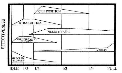
THROTTLE OPENING
Jetting Your Carb Circuits
To visualize how the various circuits overlap, please refer to the jetting chart. Always remember to change one carburetor component at a time and keep a record of your changes.
ZERO THROTTLE OPERATION (IDLE CIRCUIT)
IDLE SCREW:
Depending on your type of riding, adjust the minimum idle speed to desired RPM making sure the engine is up to operating temperature. If you do not desire any idle, make sure you turn in the adjusting screw just enough so the engine will not idle. This is especially important on Keihin PJ Series carbs in that the idle adjust knob (#4 in illustration) cannot be completely closed. Such an adjustment will result in a sluggish response off idle.
AIR/FUEL ADJUSTMENT SCREW:
The carburetor pictured in the exploded view uses an air adjustment screw (#5 in illustration) that is located "upstream" of the throttle valve (slide) and meters air. Turning the air screw counter-clockwise leans the mixture off idle. Some carburetors have this screw located "downstream" of the throttle valve, in which case, the screw meters fuel and opening the screw (counter-clockwise) results in a richer mixture. The idle screw usually has a range of one to two turns out from fully closed. If you need to adjust above or below this range, then the fuel jet will probably need to be replaced with a richer/leaner jet as required. Consult your owner's manual for the standard setting.
1/8 TO 1/4 THROTTLE
SLOW JET AND THROTTLE VALVE CUTAWAY:
Note - keep in mind that the idle adjust screw (air/fuel screw) gives a good indication of a properly sized slow jet (#6 in illustration). The slow jet calibrates the mixture from both the idle bypass and the idle orifice in the jet block. If the idle screw is properly adjusted, but the engine does not have good response when the throttle is wicked open, it is usually a sign of a lean mixture and the slow jet will need to be replaced with one size larger (richer) and the air/fuel screw re-adjusted. Consequently, if the throttle is only partially opened, such as in a trailing throttle situation, and the bike tends to load up, emitting a deep tone when the throttle is returned to full open, it is usually a sign of a rich slow jet. If the slow jet does not clean up this part of the circuit, the slide can be substituted for one with a different cutaway. The higher the number, the larger the cutaway will be, allowing more air to the jet block/nozzle screen leaning the mixture and, conversely, a smaller cutaway will richen the mixture with a greater effect up to 1/4 throttle.
1/4 TO 3/4 THROTTLE
JET NEEDLE:
The jet needle (#2 in illustration) is comprised of five major elements.
- Straight diameter section - In Keihin carburetors, either the last two digits or last letter denotes the diameter of the needle. The higher the last two digits, the leaner the needle and the lower the letter, the richer the needle. By going to a thinner needle, there is a larger area between the jet needle and the needle jet supplying a richer mixture.
- Length of the straight section - This determines at which point the needle taper will start relative to the clip position. If you have to run a needle in the highest clip position, a needle with a longer straight section should be used.
- Needle Clip Position - This works in conjunction with the length of the straight section. If the engine is too rich above 1/4 throttle, raising the needle clip (#1 in illustration) will lean the mixture.
- Needle Taper - A larger taper will result in a leaner mixture in the first half of the taper and a richer mixture in the last half of the needle. For example, a 1.34 taper will be richer in the first half and leaner in the second half of the taper than a 1.45 taper needle.
- Number of tapers - The needle can have one or more tapers; the number of tapers is not usually changed.
NEEDLE JET:
The needle jet/nozzle controls the fuel/air mixture up to 3/4 throttle. How it overlaps with the jet needle depends on the jet orifice inner diameter, air bleed holes and type of nozzle screen. Most modern Japanese carburetors use a fixed needle jet/nozzle assembly which cannot be removed. It your carburetor has a removable needle jet/nozzle, please contact the manufacturer in order to decipher the nozzle code. It is advisable not to calculate how rich/lean the needle jet is by using exclusively the nozzle inside diameter to needle outside diameter discharge area.
WIDE OPEN THROTTLE
MAIN JET:
The best track side method to determine the size of the main jet (#7 in illustration) is to fully load the engine on a long straightaway or hill. At the end of the stretch, chop the throttle and hit the kill button simultaneously. Now pull the spark plug. The parts of the plug you should be looking at are the positive electrode and last 1/4 of the ceramic insulator. Best power will usually result in a very light tan colored insulator tip and dark colored ring around the tip of the electrode. The electrode itself should have fairly sharp edges. For example, if the ceramic insulator has a nice tan coloring but the electrode has a white ring around the tip and the plug is of the correct heat range, then you can easily run a size larger on the main jet.
When jetting your main jet, try to remember to jet for the best power in a specific situation. As you gain experience and knowledge, you will be able to use other methods to determine your jetting. A good tuner can "feel" most of the circuits by slowly reving a parked bike, or just by looking at the color of the unpainted pipe and silencer.