Police 6: Turn signals & spot lights
Created:
Updated:
Applicable to these part numbers:
- Route the harness from inside the dash (I prefer the left grommeted hole) to under the fuel tank in the space provided by the frame.
- Make the connections at the dash
- The blue wire (with insulation stripped and wire tinned with solder) is secured with a set screw to a terminal of the left push-pull switch. It does not matter which set screw is used.
- The blue wire with the insulated 6.3 mm female spade terminal is connected to the indicator light for the spot lights.
- The white/black wire with the insulated 6.3 mm female spade terminal is connected to the indicator light for the right turn signal circuit.
- The yellow/black wire with the insulated 6.3 mm female spade terminal is connected to the indicator light for the left turn signal circuit.
- Make the connections under the fuel tank
- The blue wires sharing the non-insulated 6.3 mm female spade terminal are connected to the 3 connection female spade connector distributing current to the spot lights.
- The white/black wire with the non-insulated 6.3 mm female spade terminal is connected to the 3 connection female spade connector for the right turn signal circuit.
- The yellow/black wire with the non-insulated 6.3 mm female spade terminal is connected to the 3 connection female spade connector for the left turn signal circuit.
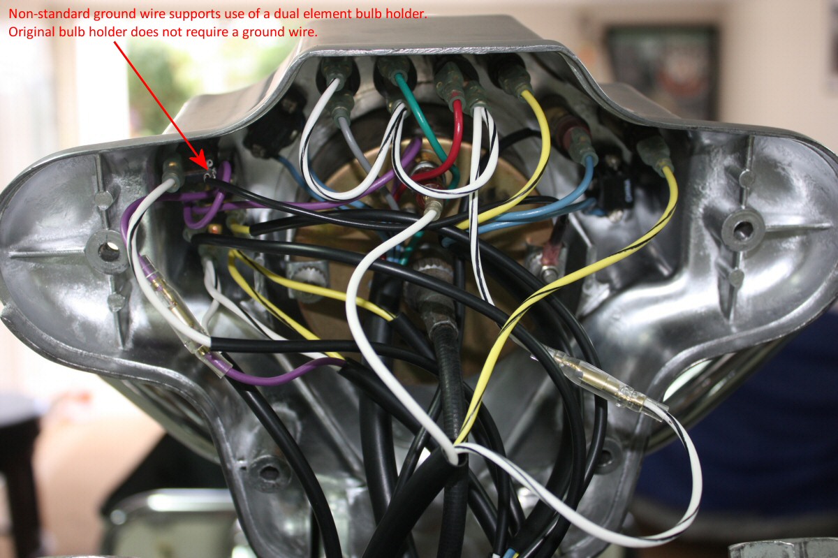
Photo courtesy of Robert Bear
Wolfe (Aloha).
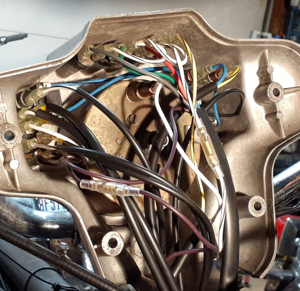
Photo courtesy of Richard Mattrass.