Police 8: Handlebar switch - early right
Created:
Updated:
Applicable to these part numbers:
IMPORTANT NOTE: It is very easy to destroy original or aftermarket switches when using a conventional soldering iron. Even if you know exactly what you are doing and are very experienced with soldering procedures, the switches can very easily be rendered useless. Rather than using solder, I strongly recommend the following:
- Use a conductive epoxy to secure the wires to the switch. Most epoxies, including JB Weld, do not conduct electricity. MG Chemicals makes a conductive epoxy that I've used with excellent results (part number 8331D). Atom Adehesives AA-PROD 123 is a less expensive epoxy that Charlie Mullendore of Antietam Classic Cycle reports works well. Nick Rossi contacted Atom Adhesives directly and found that AA-Duct 902 is the
most conductive epoxy
and that AA-Duct 916 ismore suitable for motorcycle applications as it is flexible once cured and will be more resistant to vibration
. Nick prefers the AA-Duct 916 (available from Amazon).
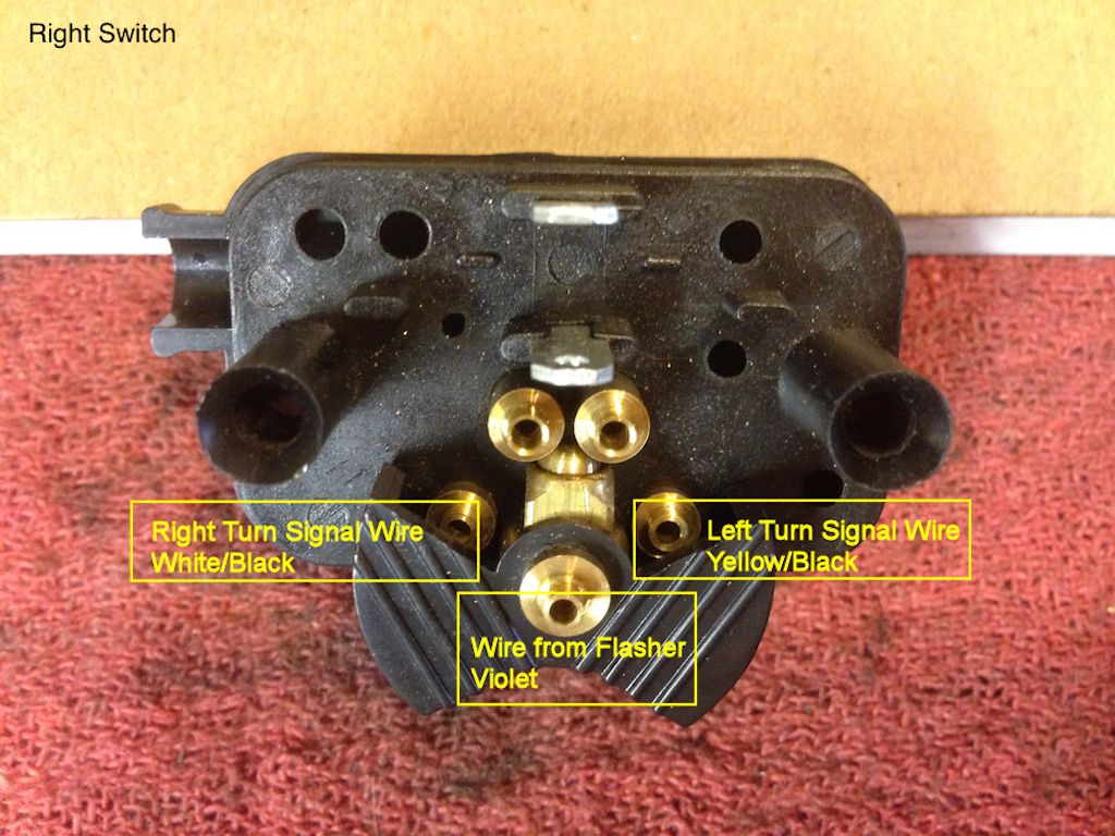
Photo courtesy of Stephen Gonzales.
The wires from the right handlebar switch (purple, white/black, yellow/black) are routed along the handlebar, then up through the holes in the upper triple tree plate to the toggle switch. The two wires that share terminals are then routed back down through the holes in the upper triple tree plate, and on to each front turn signal.
- The white/black wire with the 6.3 mm female spade terminal is connected to the toggle switch. Connect this terminal to the toggle switch terminals at the opposite end from the where the purple wires are connected.
- The yellow/black wire with the 6.3 mm female spade terminal is connected to the toggle switch. Connect this terminal to the toggle switch terminals at the opposite end from the where the purple wires are connected.
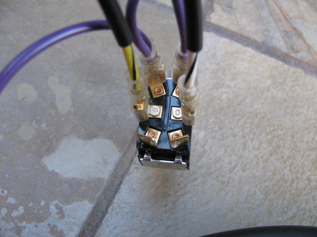
Connections to the toggle switch
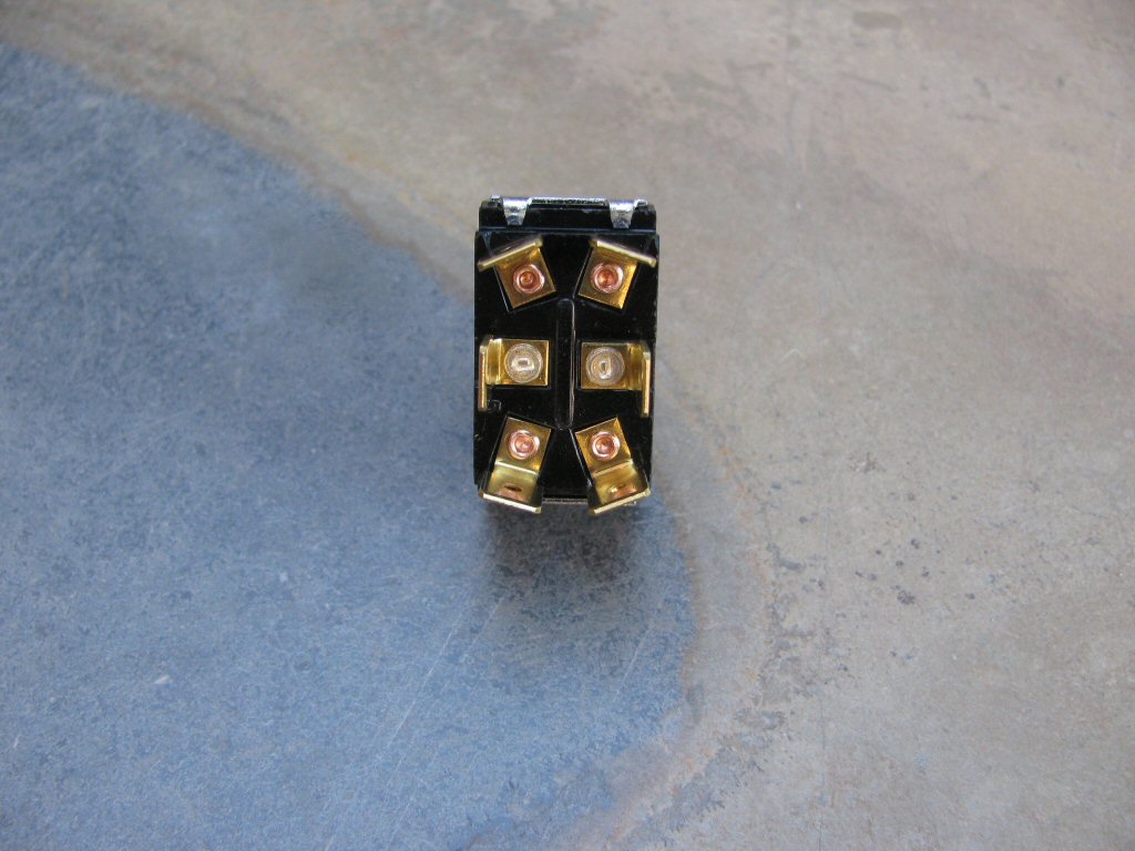
The terminals on the bottom of the toggle switch. Photo courtesy of Gregory Bender.
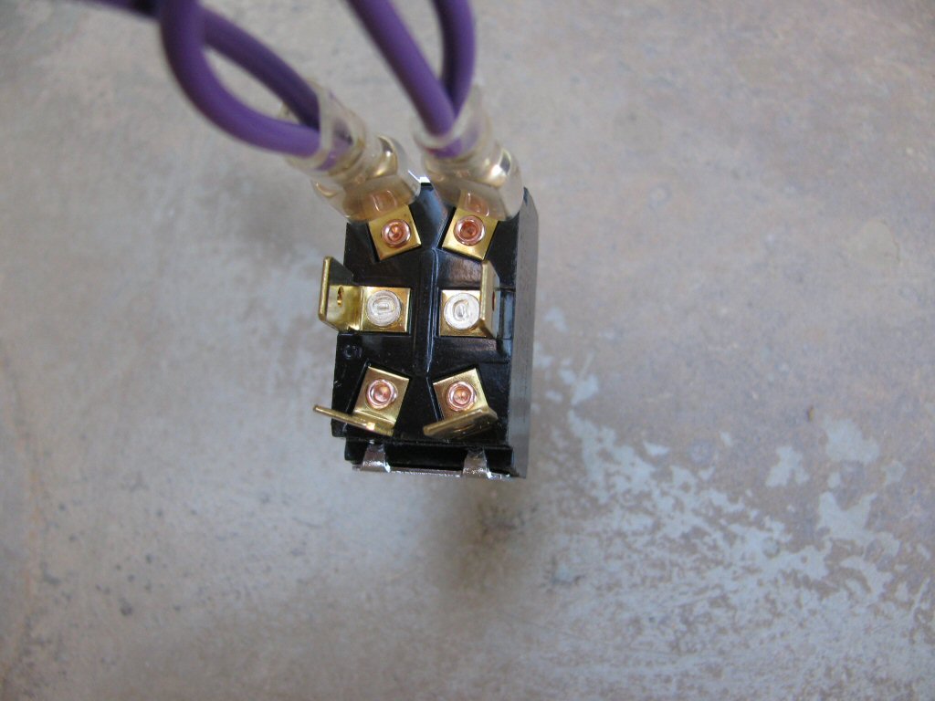
The two purple wires from the main harness are connected to the two terminals on one end of the toggle switch (it does not matter which end). Photo courtesy of Gregory Bender.
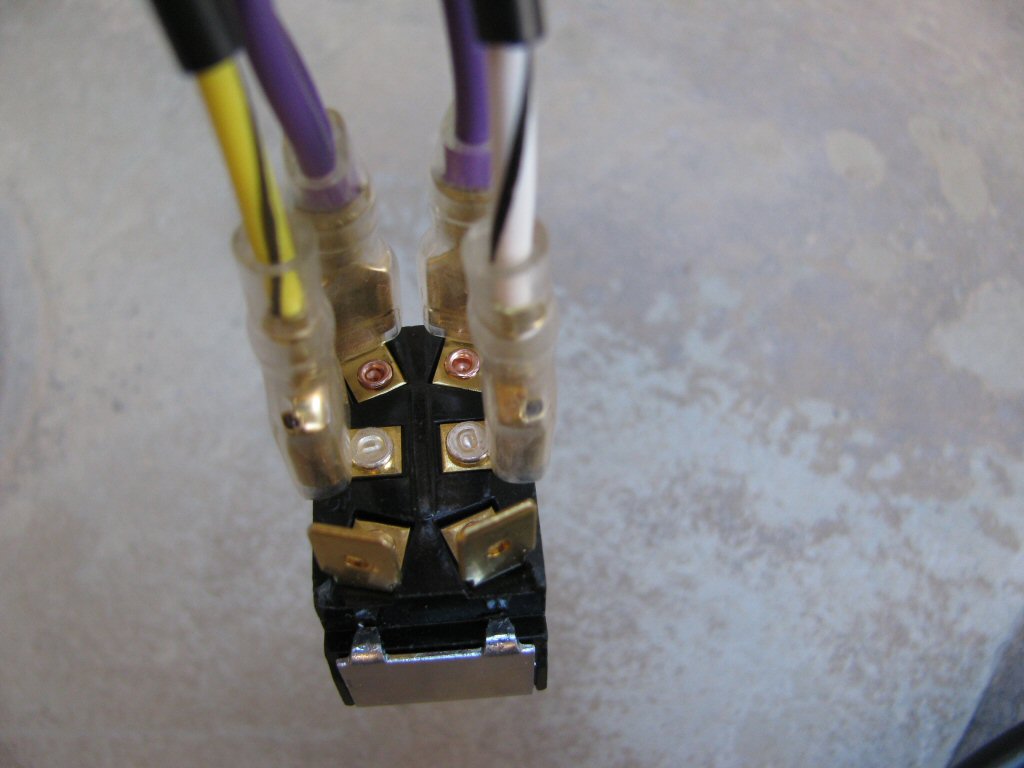
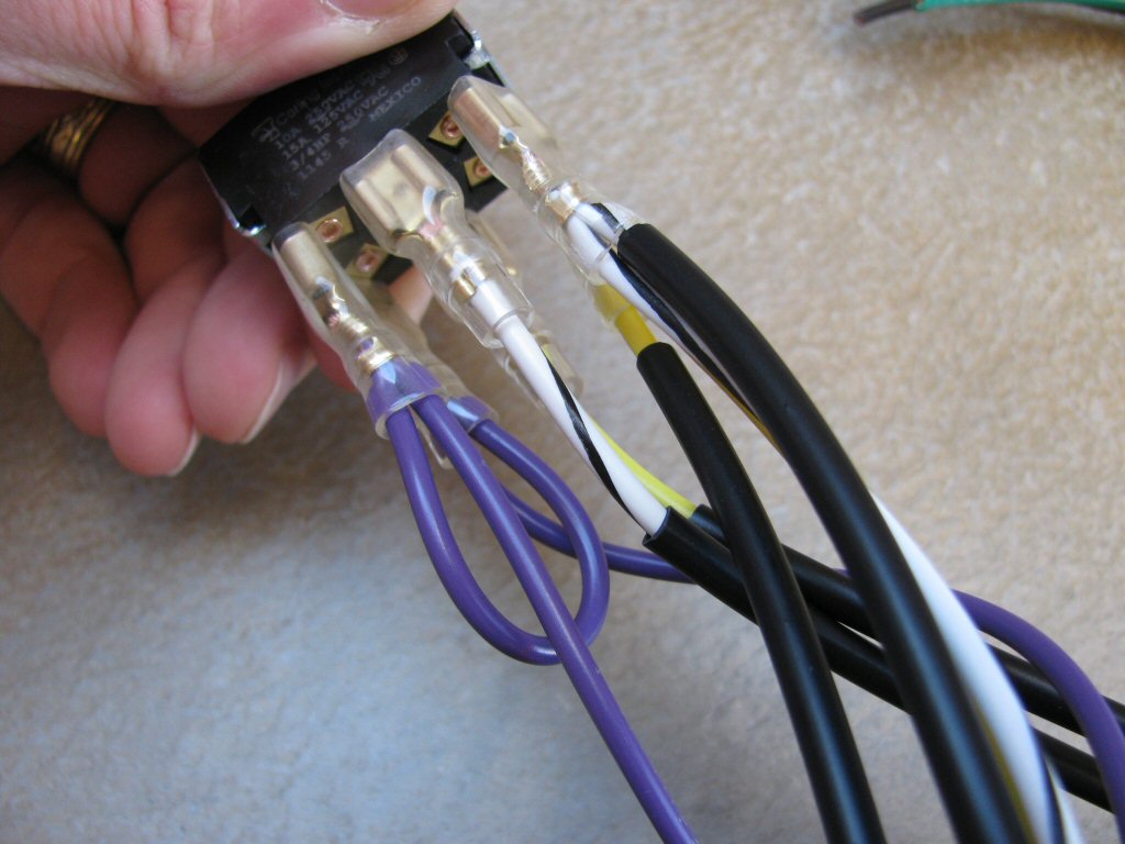
The white/black and yellow/black wires from the toggle switch to 3 connection female spade connectors
sub-harness are connected to the middle terminals on the toggle switch.Photo courtesy of Gregory Bender.
The white/black and yellow/black wires from the toggle switch to 3 connection female spade connectors
sub-harness are connected to the middle terminals on the toggle switch.Photo courtesy of Gregory Bender.
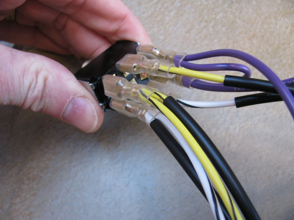
The white/black and yellow/black wires from the turn signal switch are connected to the two terminals on the opposite end of purple wires on toggle switch. Note how the yellow/black wires are on the same side. Photo courtesy of Gregory Bender.
The white/black and yellow/black wires from the turn signal switch are connected to the two terminals on the opposite end of purple wires on toggle switch. Note how the white/black wires are on the same side. Photo courtesy of Gregory Bender.
- The purple wire with the 4 mm male bullet terminal is connected to the purple wire with the 4 mm female bullet terminal from the main harness.
- The white/black wire with the 6.3 mm female spade terminal is connected to the right front turn signal.
- After you have routed all of the wires and know precisely the length you need, connect the extension wires to the right front turn signal wire. Please plan carefully, too much length is nearly as bad as not enough.
- Cut the provided extension wires to length.
- Cut the provided sheathing to length.
- Slide the sheathing over the extension wires.
- Slide the provided heat shrink over the extensions.
- Strip the insulation from the end of the extension wire.
- Strip the insulation from the end of the right front turn signal wire.
- Crimp the striped ends together using the provided butt crimp.
- Slide the heat shrink over the butt crimp and shrink it.
- Slide the sheathing over the finished assembly.
- After you have routed all of the wires and know precisely the length you need, connect the extension wires to the right front turn signal wire. Please plan carefully, too much length is nearly as bad as not enough.
- The yellow/black wire with the 6.3 mm female spade terminal is connected to the left front turn signal.
- After you have routed all of the wires and know precisely the length you need, connect the extension wire to the left front turn signal wire. Please plan carefully, too much length is nearly as bad as not enough.
- Cut the provided extension wires to length.
- Cut the provided sheathing to length.
- Slide the sheathing over the extension wires.
- Slide the provided heat shrink over the extensions.
- Strip the insulation from the end of the extension wire.
- Strip the insulation from the end of the left front turn signal wire.
- Crimp the striped ends together using the provided butt crimp.
- Slide the heat shrink over the butt crimp and shrink it.
- Slide the sheathing over the finished assembly.
- After you have routed all of the wires and know precisely the length you need, connect the extension wire to the left front turn signal wire. Please plan carefully, too much length is nearly as bad as not enough.
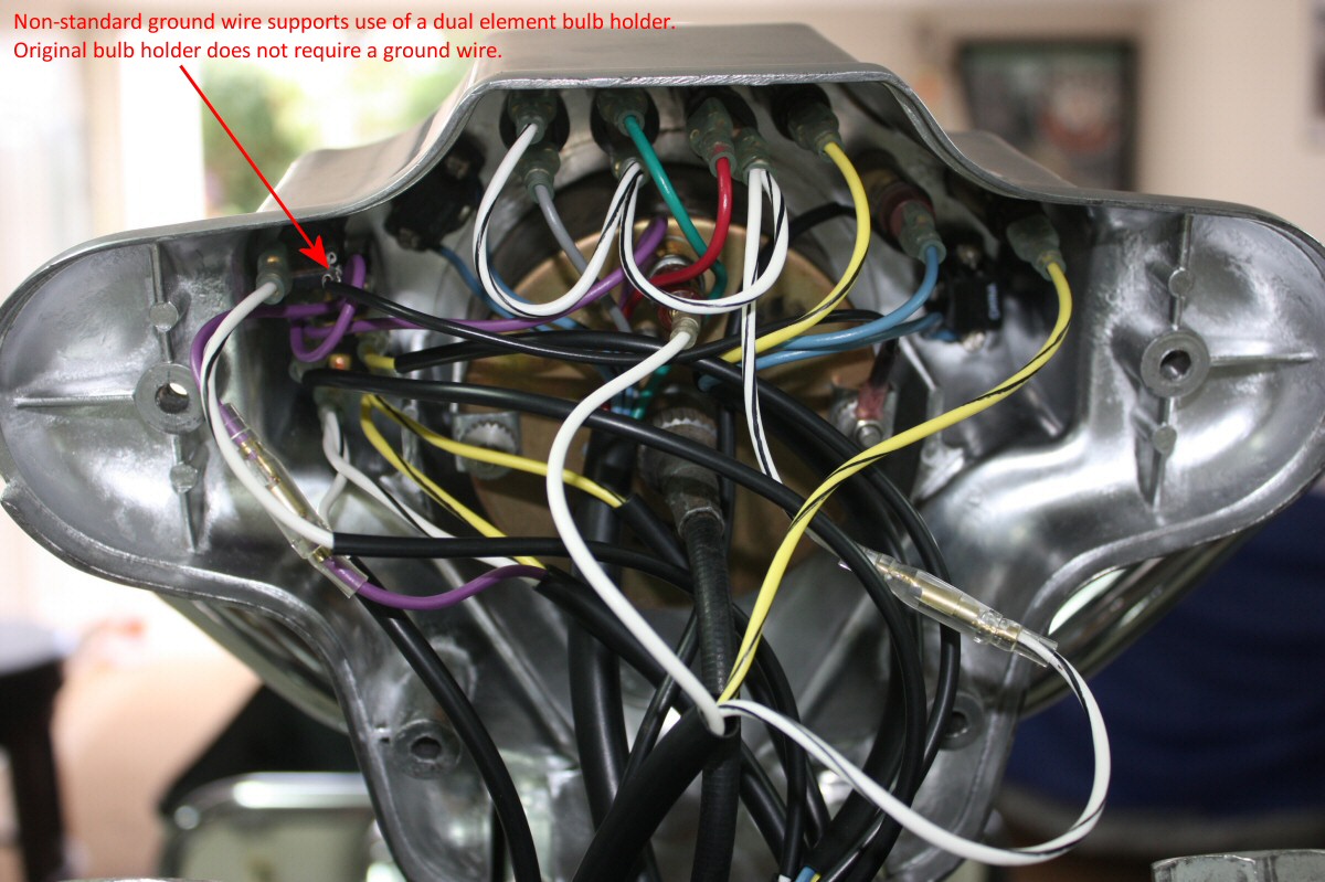
Photo courtesy of Robert Bear
Wolfe (Aloha).
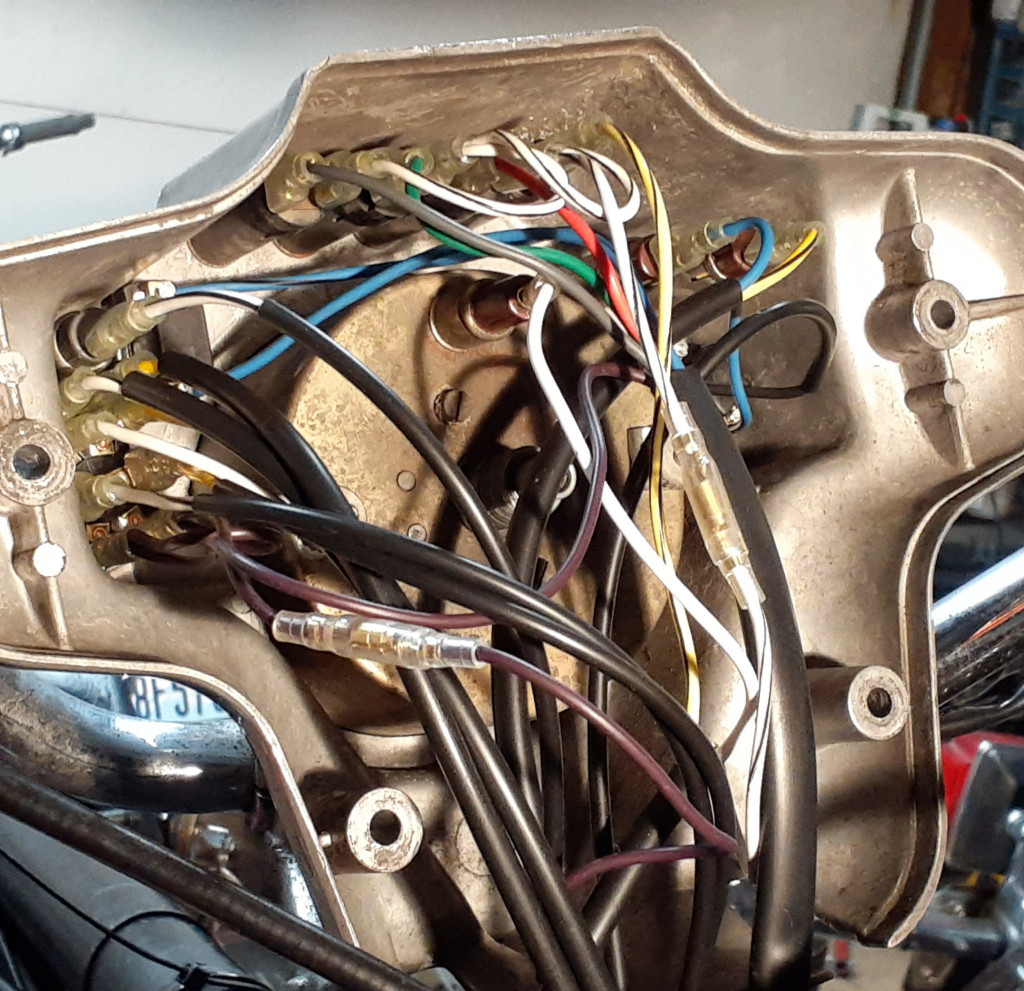
Photo courtesy of Richard Mattrass.