Moto Guzzi V7 Sport, 750 S, 750 S3, 850 T, 850 T3, 850 T3 California, V1000 I-Convert, V1000 G5, 1000 SP, Le Mans, Le Mans II, Le Mans CX 100, Le Mans III, Le Mans 1000, 1000 SP III, 1000 S, California II, California III, California 1100, California Jackal, California EV, California EV Touring, California Aluminium, California Titanium, California Special, California Special Sport, California Stone-Metal, California Stone-Touring, California Classic, California Touring, and California Vintage models
Created:
Updated:
Here is the series of photos I took during the disassembly of the transmission on my I-Convert project bike. Assembly is pretty much the reverse. It should go without saying that all the parts were fastidiously cleaned and new O-rings and seals were fitted throughout. From a 10,000 foot view perspective, here is the order of events.
Separate the converter cover from the two speed gear box.
Remove the clutch input hub assembly from the converter cover.
Disassemble the clutch input hub assembly.
Remove the clutch assembly from the two speed gear box.
Disassemble the two speed gear box.
Converter cover disassembly
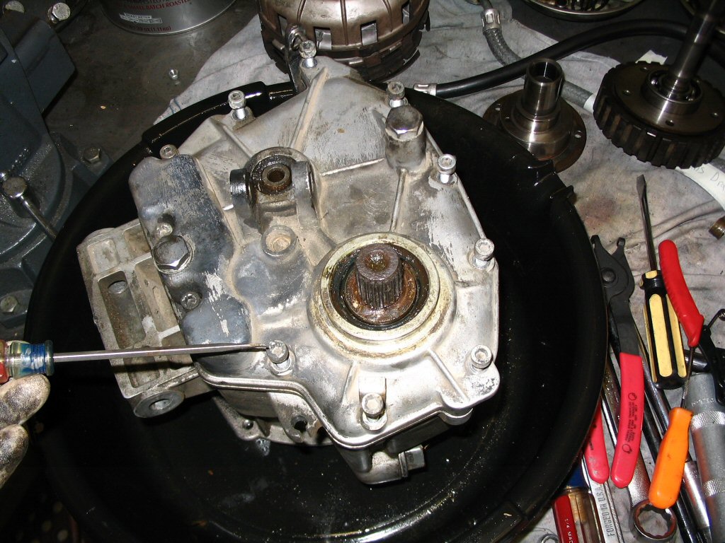
The transmission is really two separate units that are bolted together and interface with one another through dry clutch plates. The converter cover is the front unit, and it is bolted to the rear gear box unit. I began disassembly by removing the converter cover from the 2 speed gear box.
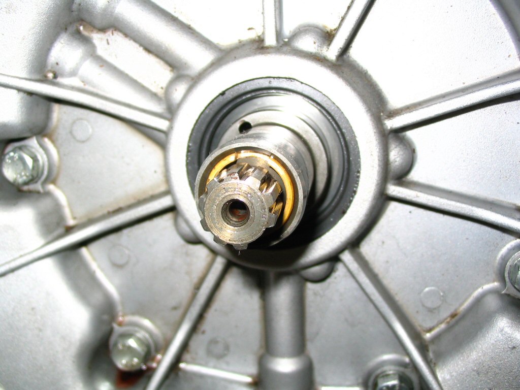
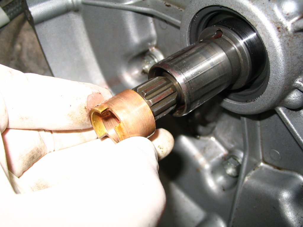
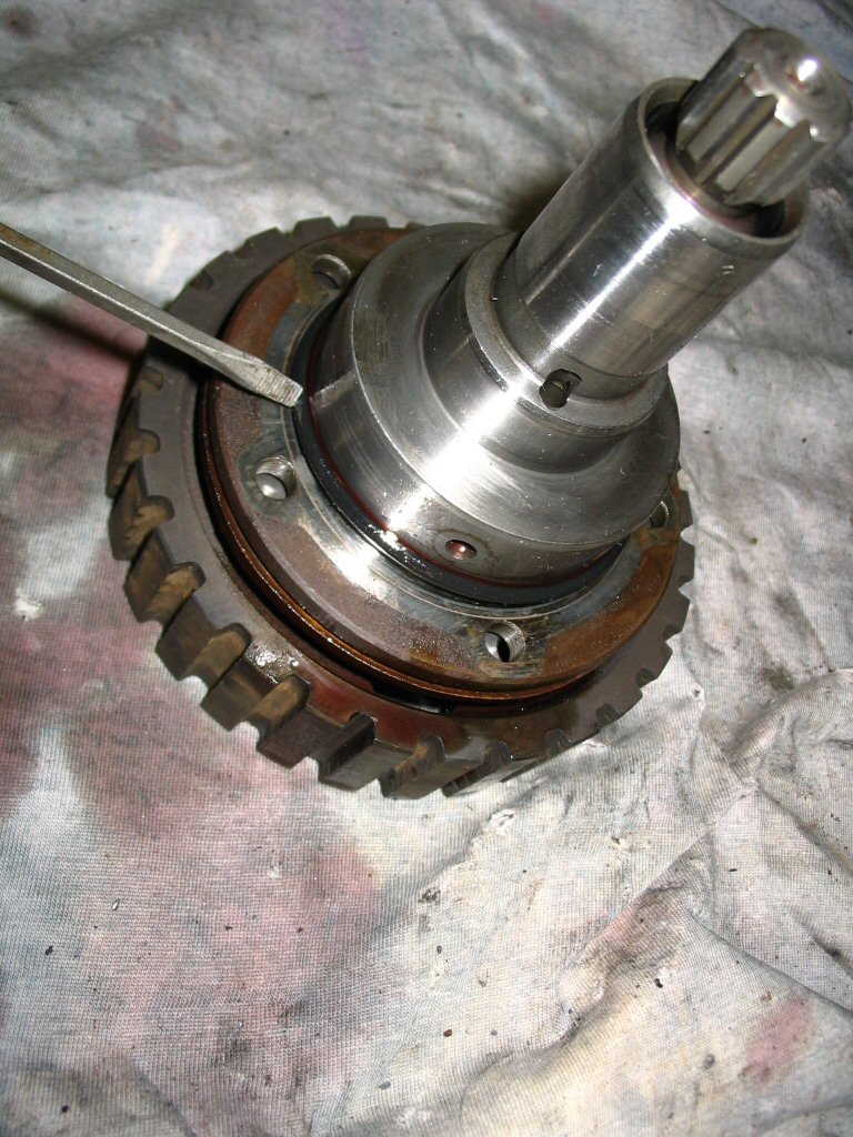
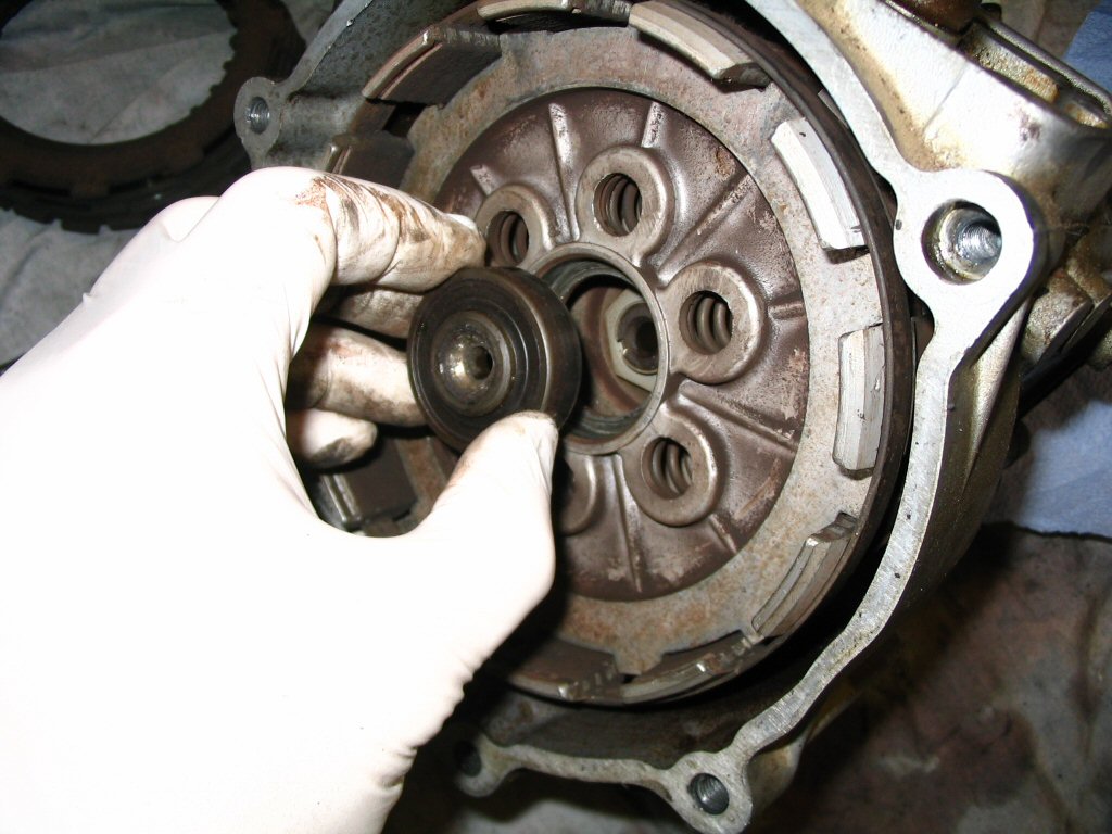
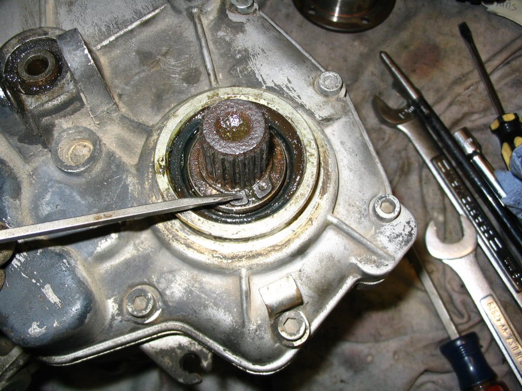
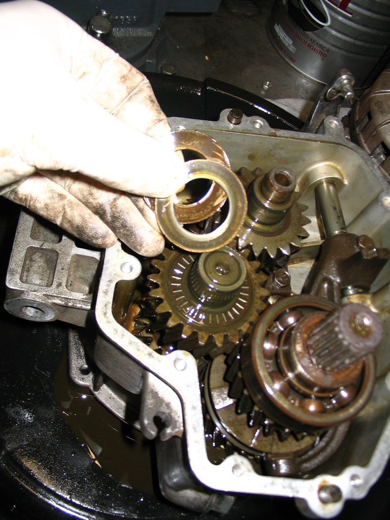
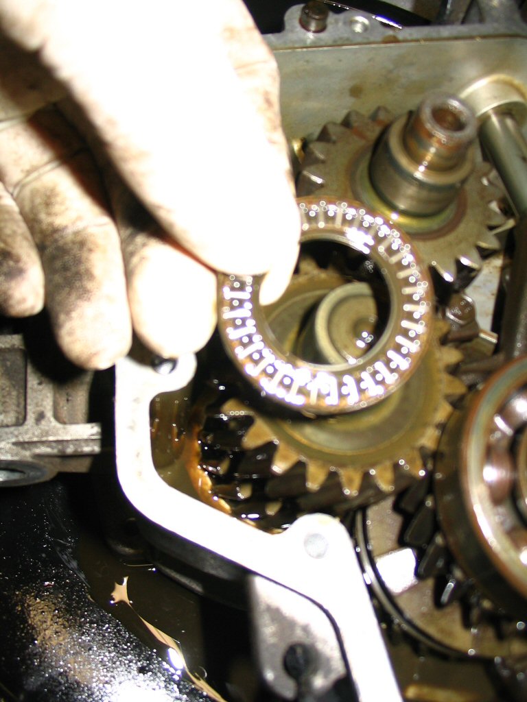
Start by removing the bronze bushing from the shaft so it won't fall out later.
Photo courtesy of Gregory Bender.
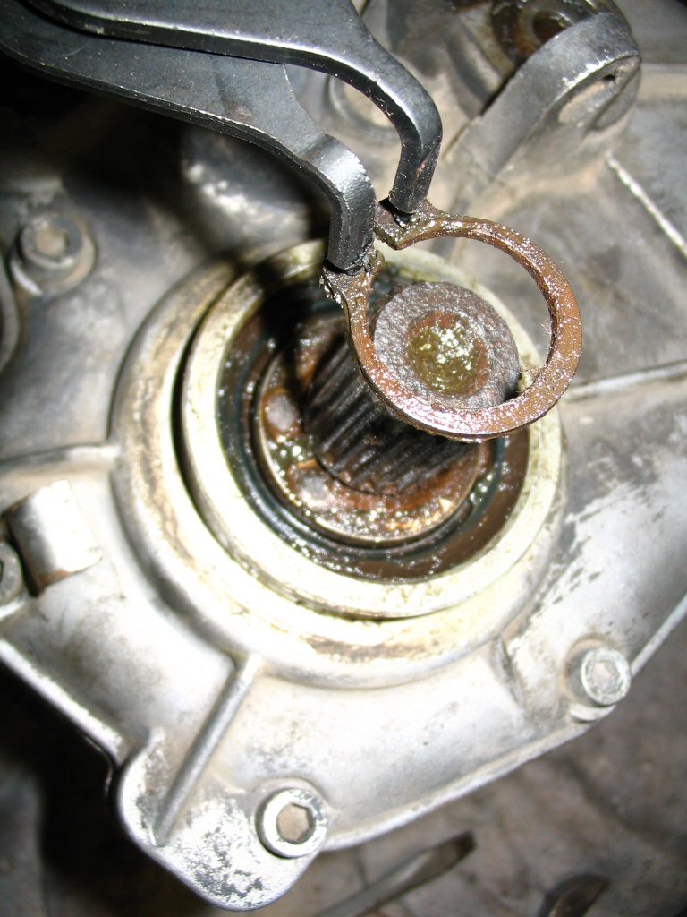
It just slides out. During reassembly the only thing that matters is that the notches face the front.
Photo courtesy of Gregory Bender.
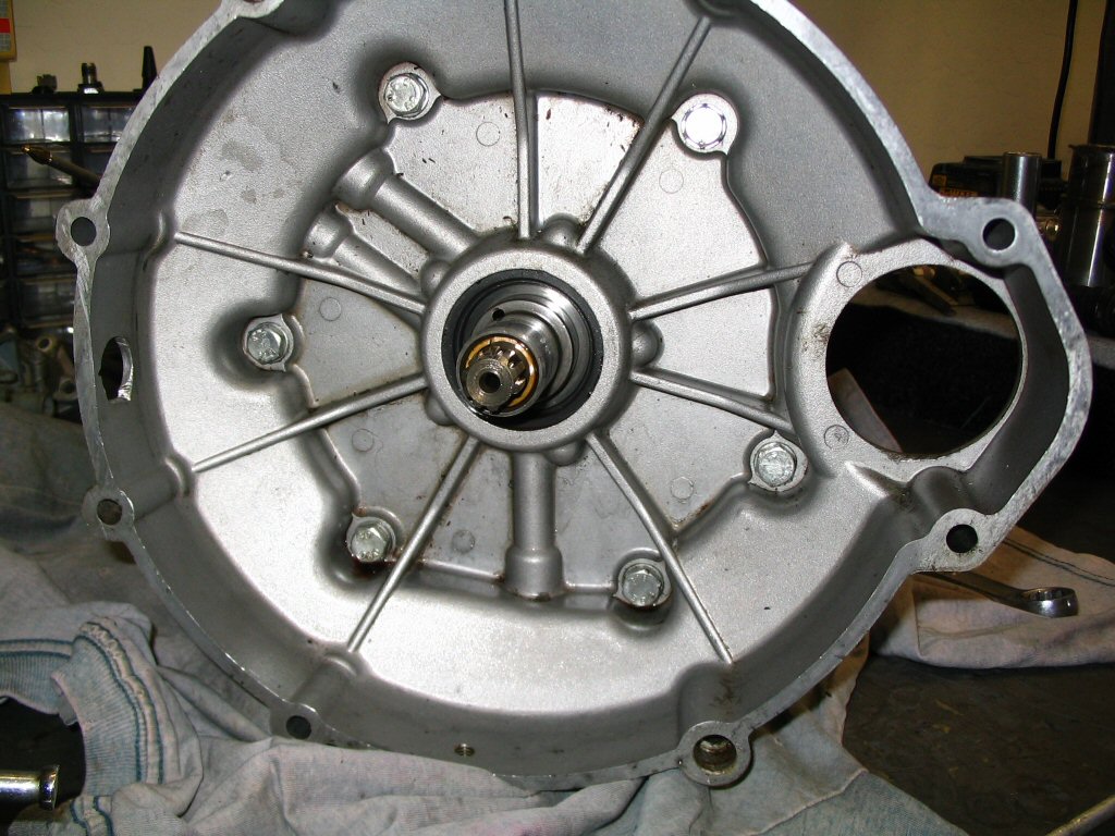
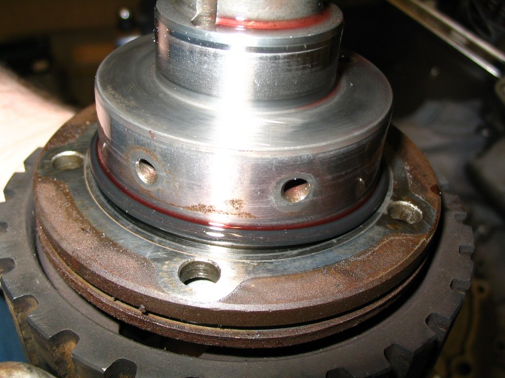
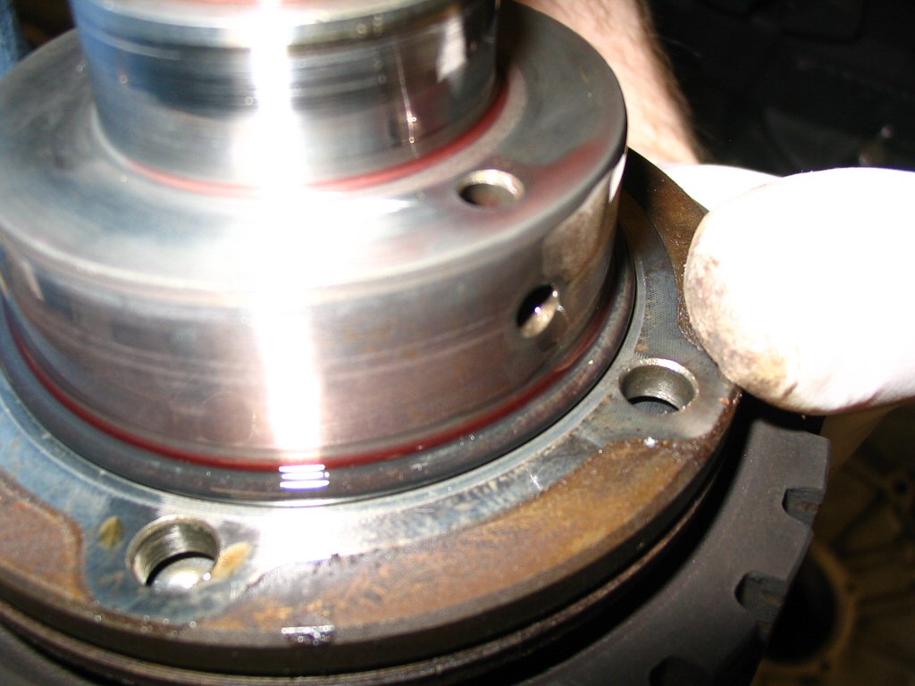
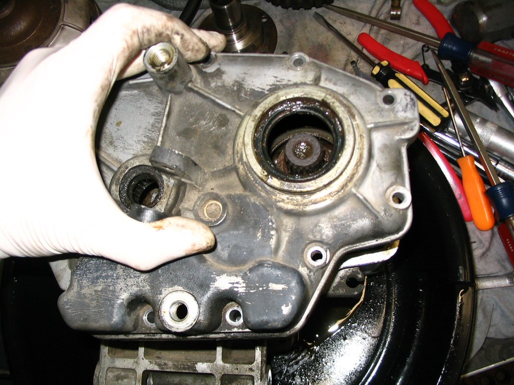
Remove the 6 bolts that secure that converter cover to the 2 speed gearbox. The converter cover will then separate from the 2 speed gearbox.
Photo courtesy of Gregory Bender.
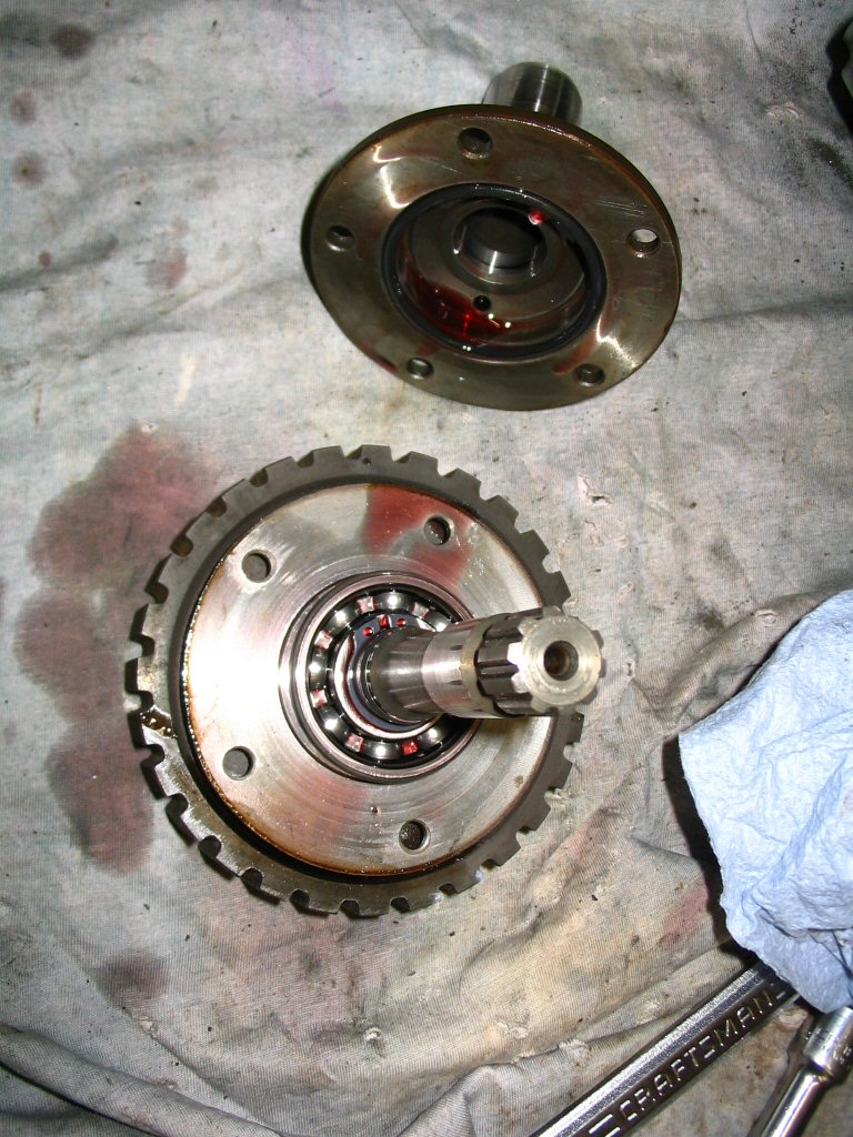
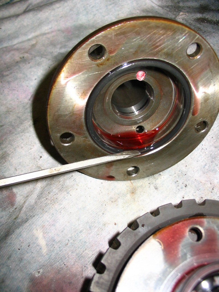
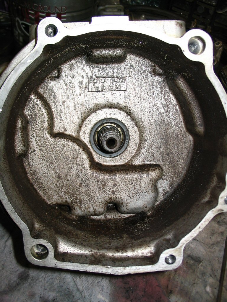
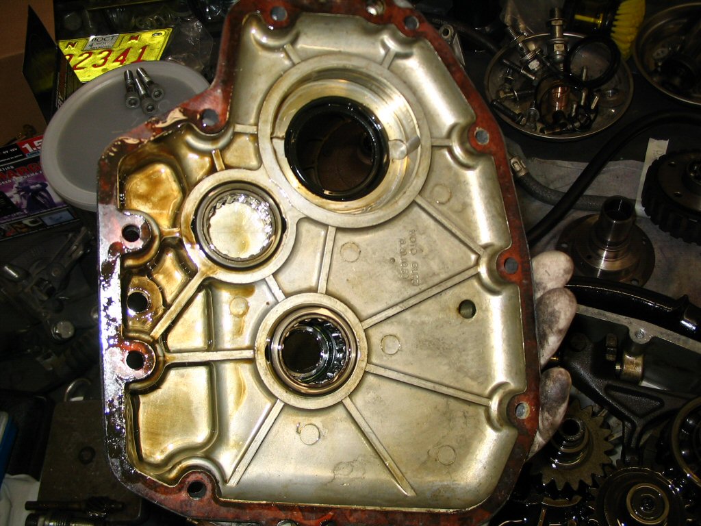
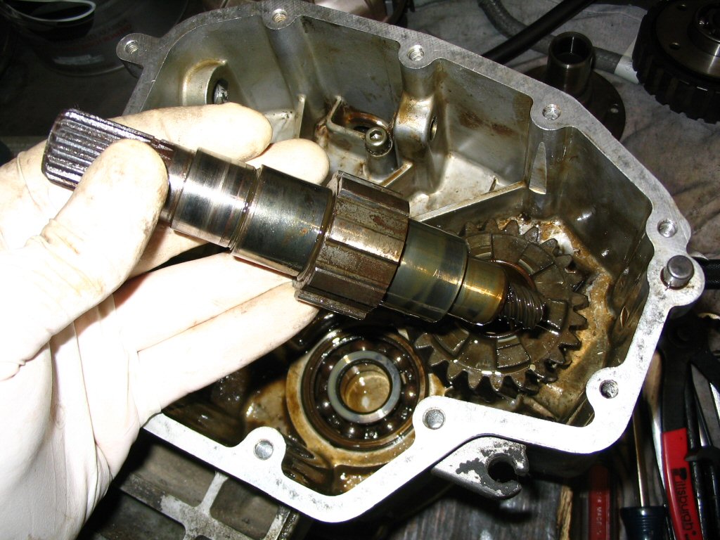
This is the rear side of the converter cover. The splined piece is the clutch input hub that interfaces with the clutch plates.
Photo courtesy of Gregory Bender.
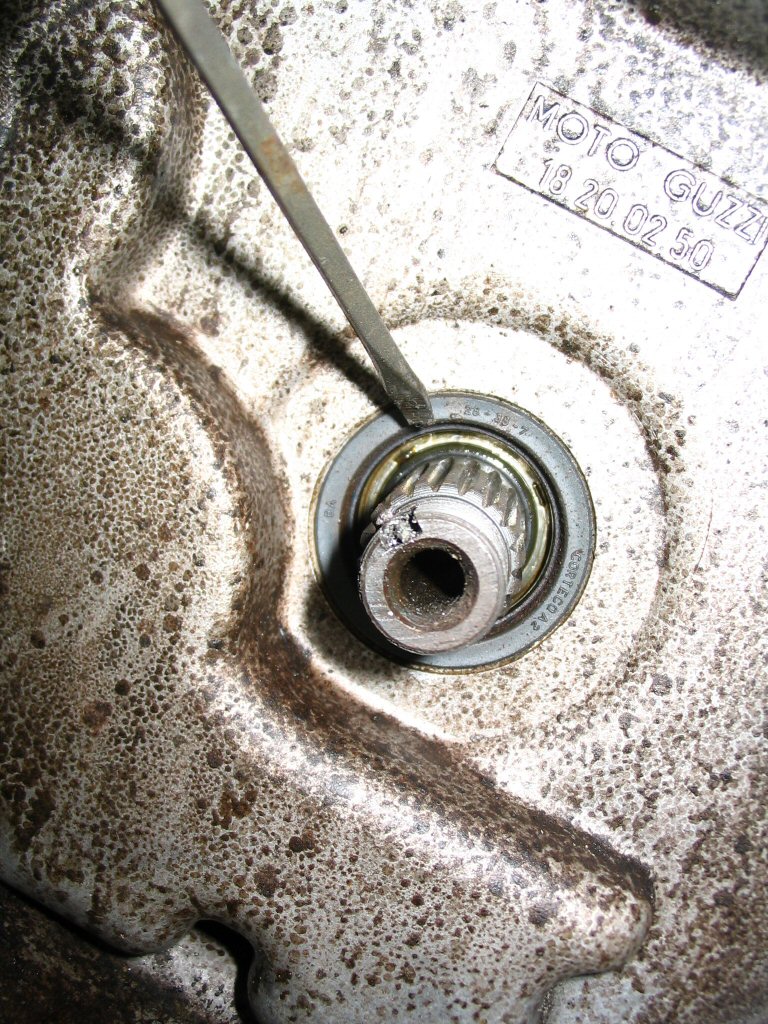
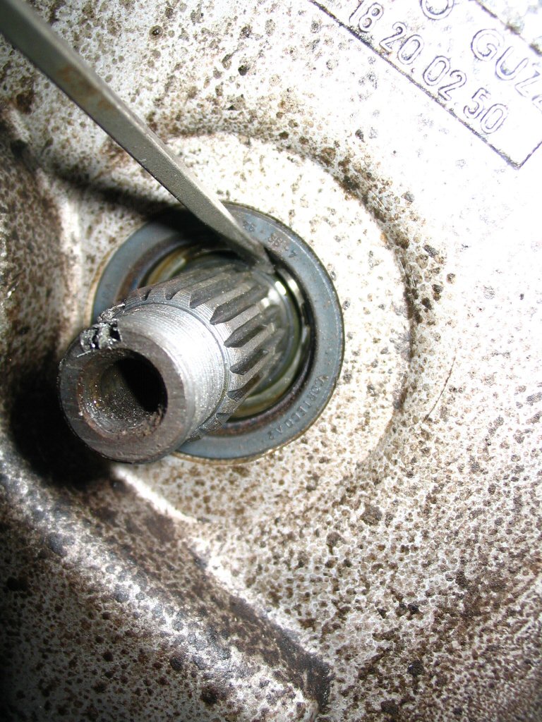
In order to remove the clutch input hub assembly from the convert cover, you need to remove 5 bolts. Rotate the clutch input hub until the bolts are visible through the access holes.
Photo courtesy of Gregory Bender.
Remove each of the 5 bolts and withdraw the assembly. The complete clutch input hub assembly should slide right out of the converter cover.
Photo courtesy of Gregory Bender.
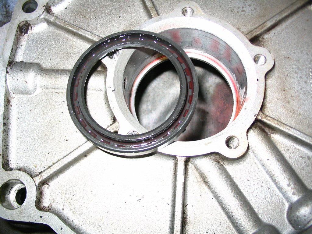
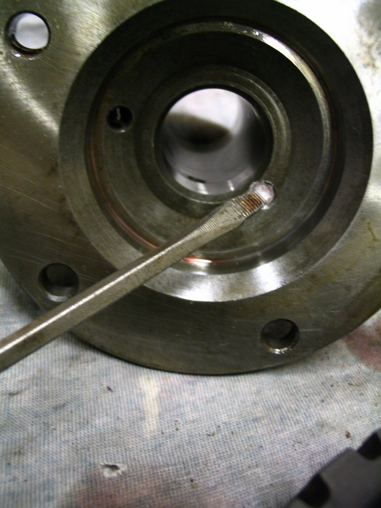
Here is the seal (MG# 90404563) and several of the passages that must be aligned with the corresponding passages in the clutch input hub assembly during reassembly.
Photo courtesy of Gregory Bender.
Drive the seal out (MG# 90404563).
Photo courtesy of Gregory Bender.
Here is how the seal (MG# 90404563) must be positioned during assembly.
Photo courtesy of Gregory Bender.
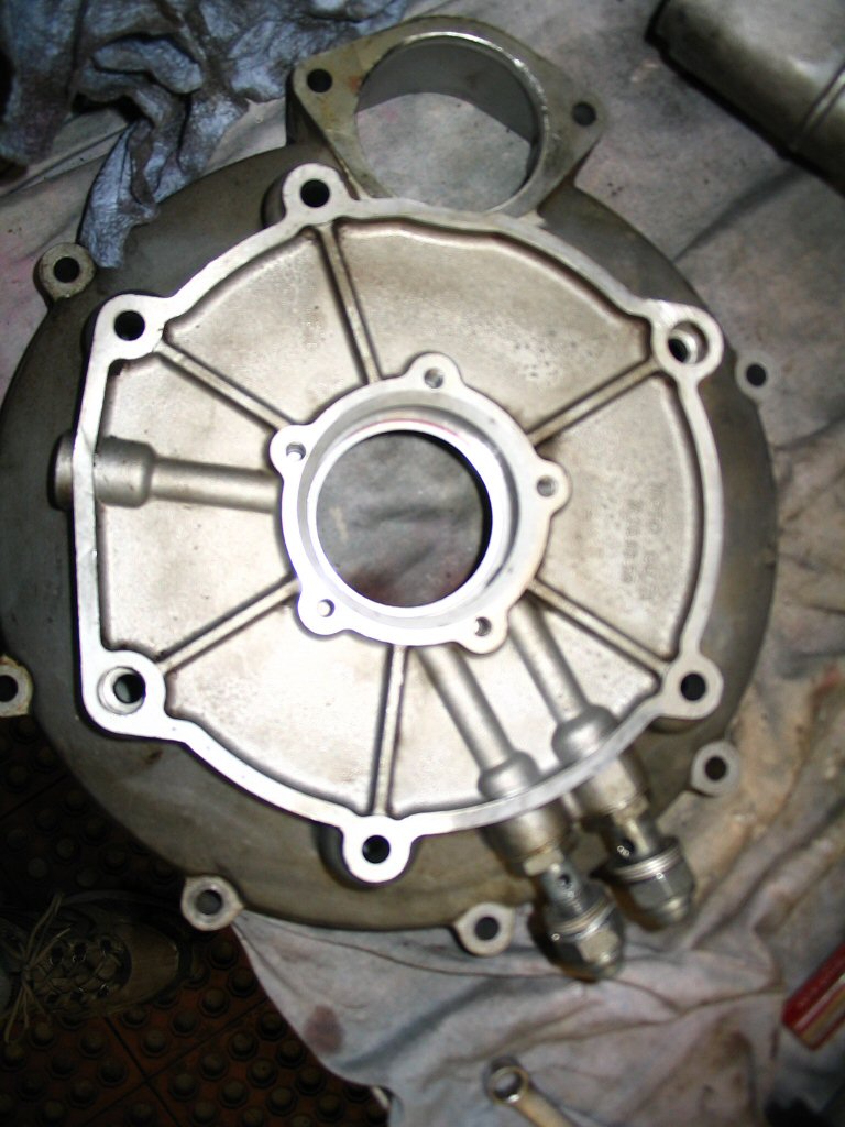
A view of the rear side of the converter cover.
Photo courtesy of Gregory Bender.
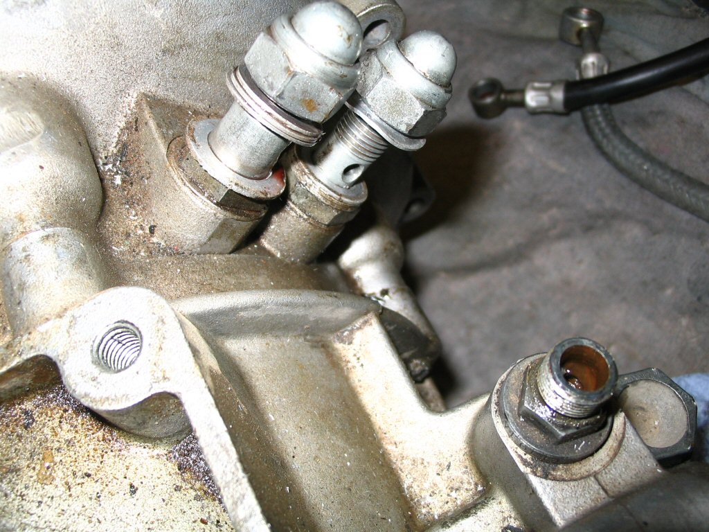
Note the use of multiple aluminum crush washers to prevent the acorn nuts from bottoming out before making a tight seal.
Photo courtesy of Gregory Bender.
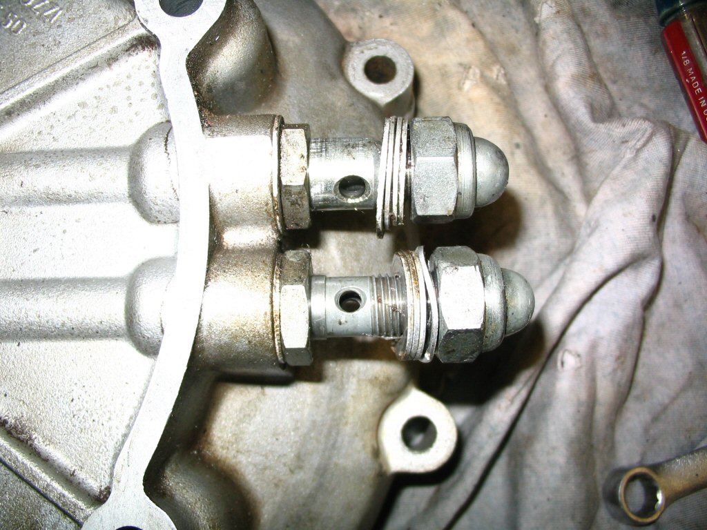
A closer view of the fittings for the oil lines. Notice the bottom one is a smaller diameter than the top one. I removed both of these fittings. That about covers the removal and disassembly of the converter cover.
Photo courtesy of Gregory Bender.
Clutch input hub disassembly
With the clutch input hub removed from the converter cover, we can disassemble it.
Now we turn our attention to disassembling the clutch input hub. Start by removing this O-ring (MG# 90706600).
Photo courtesy of Gregory Bender.
Note the holes that must align with the passageways in the converter cover during assembly. You can see that I've already started to separate the two halves that were held together by the 5 bolts.
Photo courtesy of Gregory Bender.
Here is another hole that must be aligned with the passageways in the converter cover during assembly.
Photo courtesy of Gregory Bender.
Completely separate the two halves that were held together by the 5 bolts. I was able to accomplish this using small screwdrivers and careful prying.
Photo courtesy of Gregory Bender.
Remove the O-ring (MG# 90706473) from the front half.
Photo courtesy of Gregory Bender.
This hole in the front half is supposed to be plugged (the other hole on the opposite side should not be plugged).
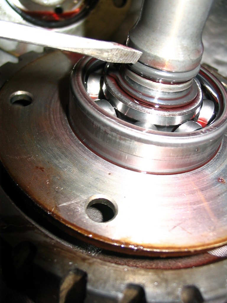
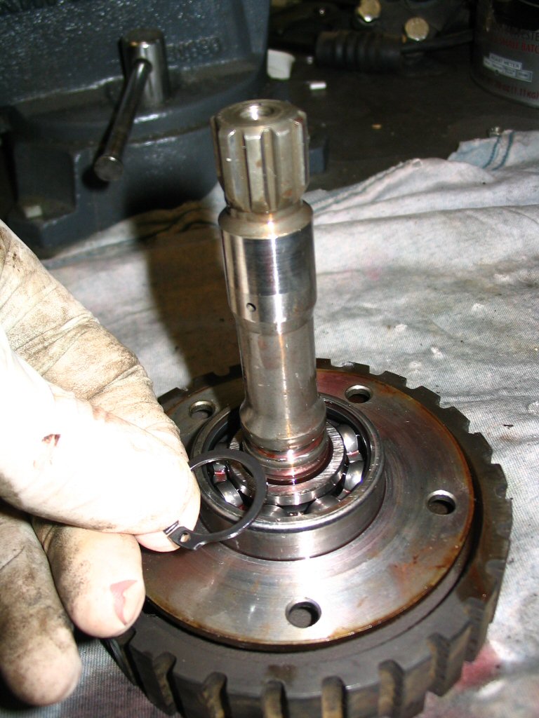
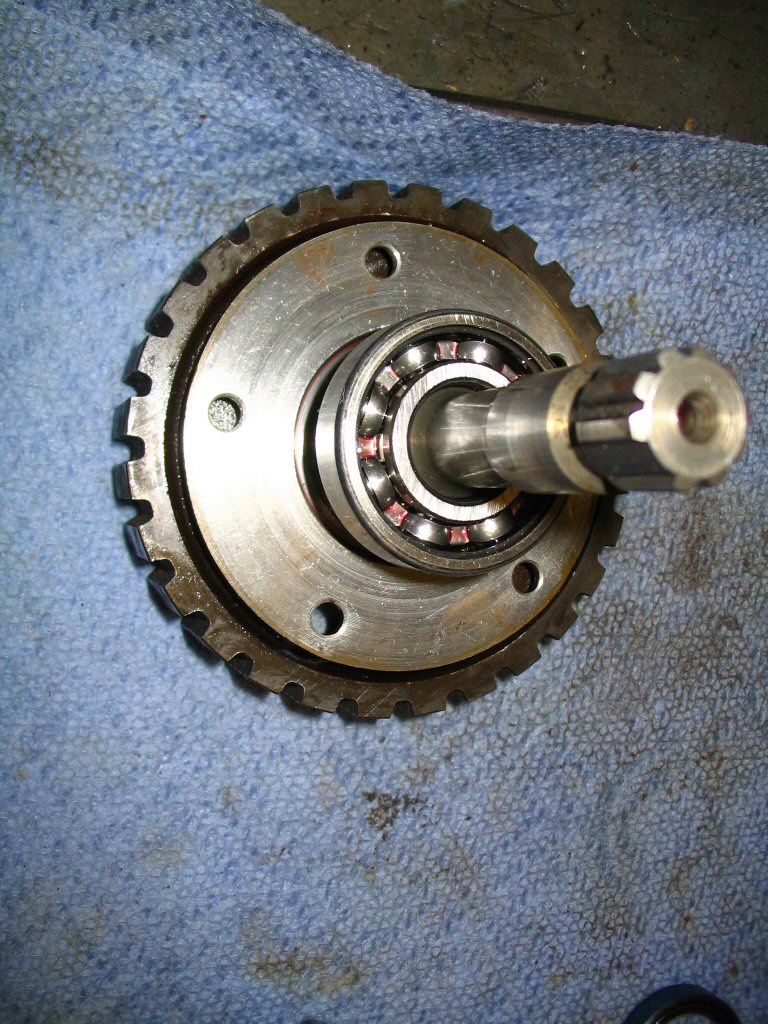
Remove the snap ring (MG# 90271020) from the shaft. This snap ring keeps the bearing in place.
Photo courtesy of Gregory Bender.
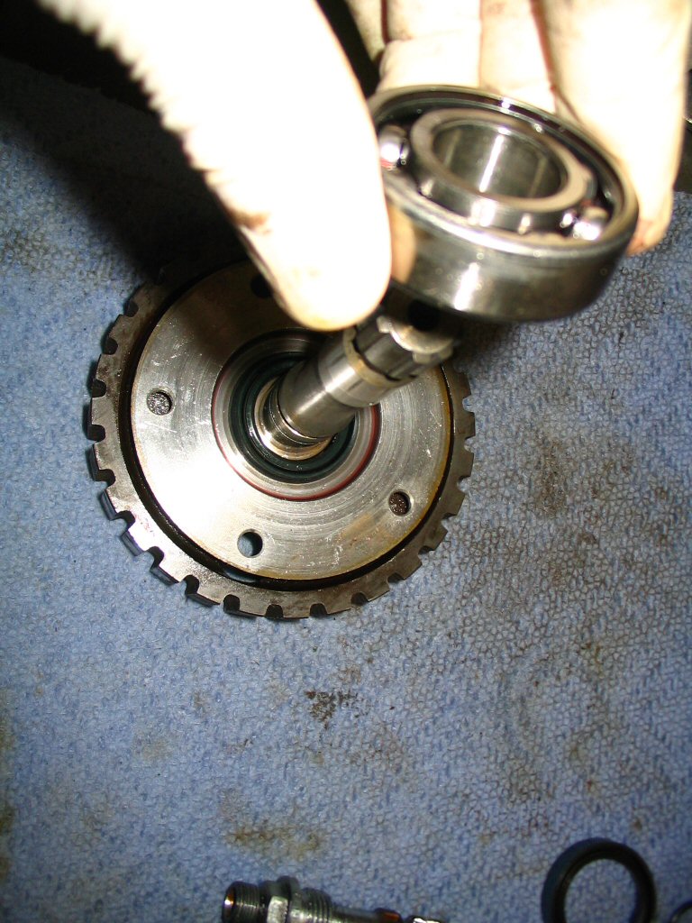
Pull the bearing (MG# 92201220) from the shaft. If I remember correctly, I needed to use a press (or puller) to pull up on the bottom half (with the 5 bolt holes). This is necessary because the bearing sits inside of it and you can't get a grip on the bottom of the bearing. Just be careful not to bend the bottom half when you use your press (or puller).
Photo courtesy of Gregory Bender.
Remove the bearing (MG# 92201220).
Photo courtesy of Gregory Bender.
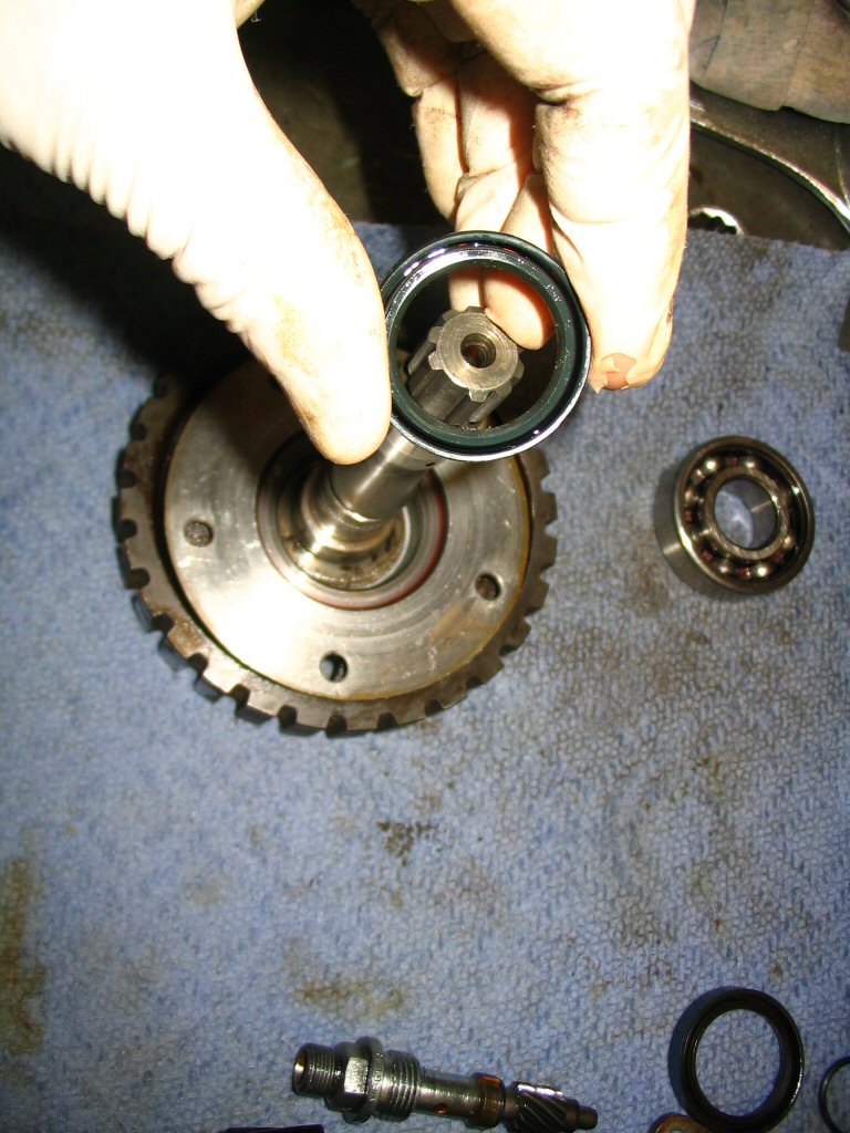
Remove the seal (MG# 90402535), note the direction that it must be installed. I'm certain I removed the seal after I'd removed the plate. I just took the picture here to be clear about assembly order, etc.
Photo courtesy of Gregory Bender.
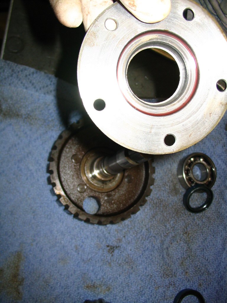
Remove the bottom plate.
Photo courtesy of Gregory Bender.
Clutch basket disassembly
The clutch basket needs to be removed before we can disassemble the gear box.
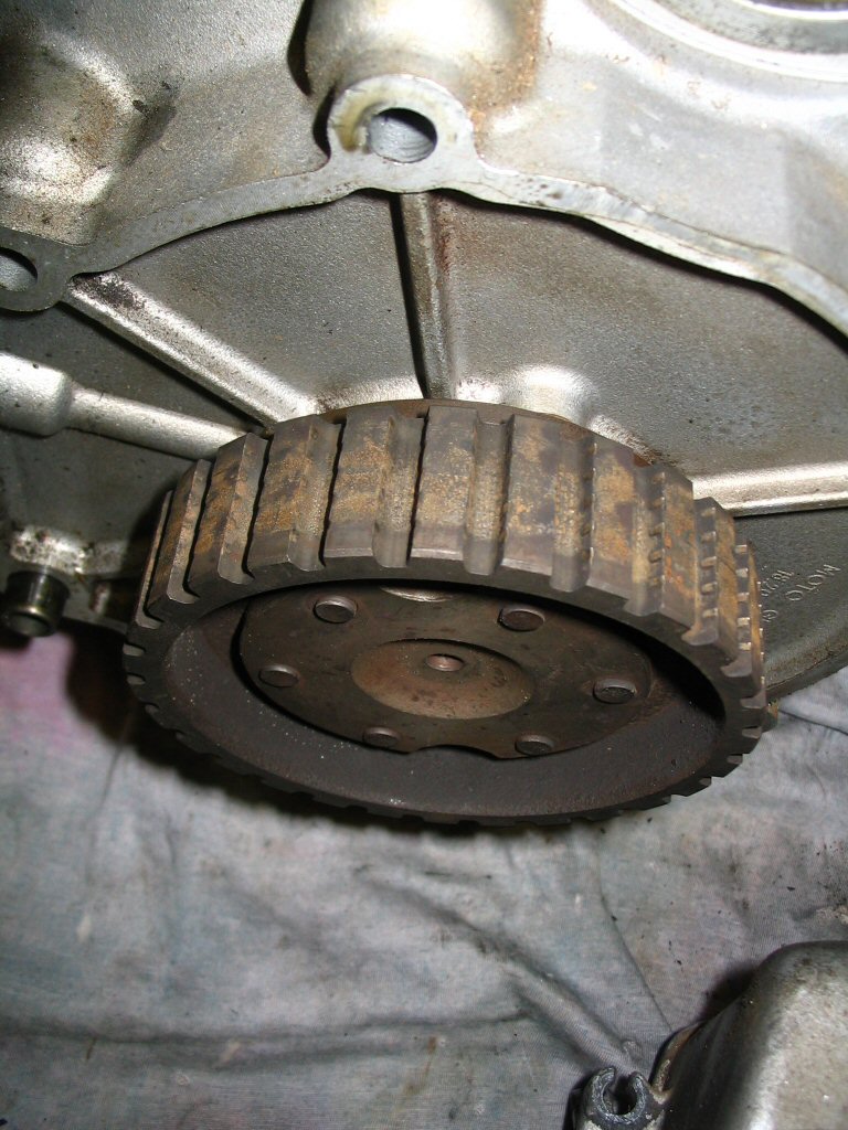
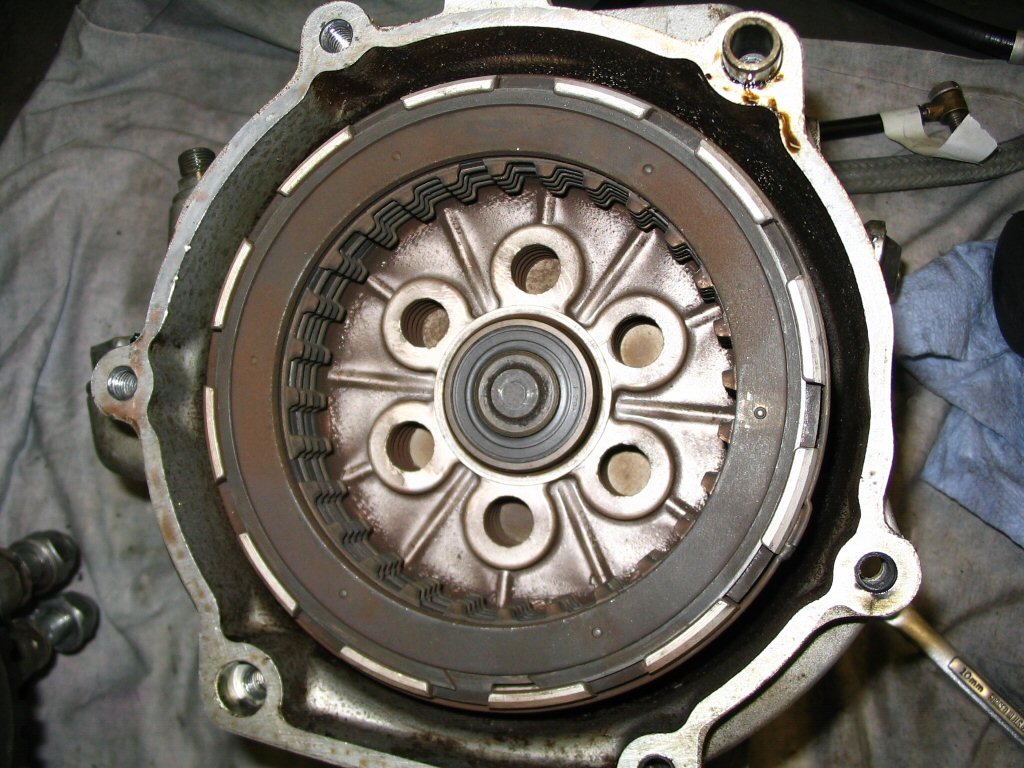
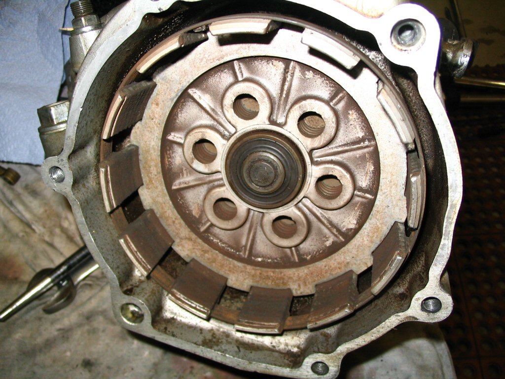
With the converter cover removed and the clutch input hub disassembled, I turned my attention to the 2 speed gearbox. Here is the stack of clutch plates installed.
Photo courtesy of Gregory Bender.
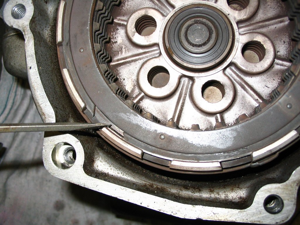
Here is the snap ring that must be removed. In order to do that, we must first take the pressure off of the clutch and intermediate plates.
Photo courtesy of Gregory Bender.
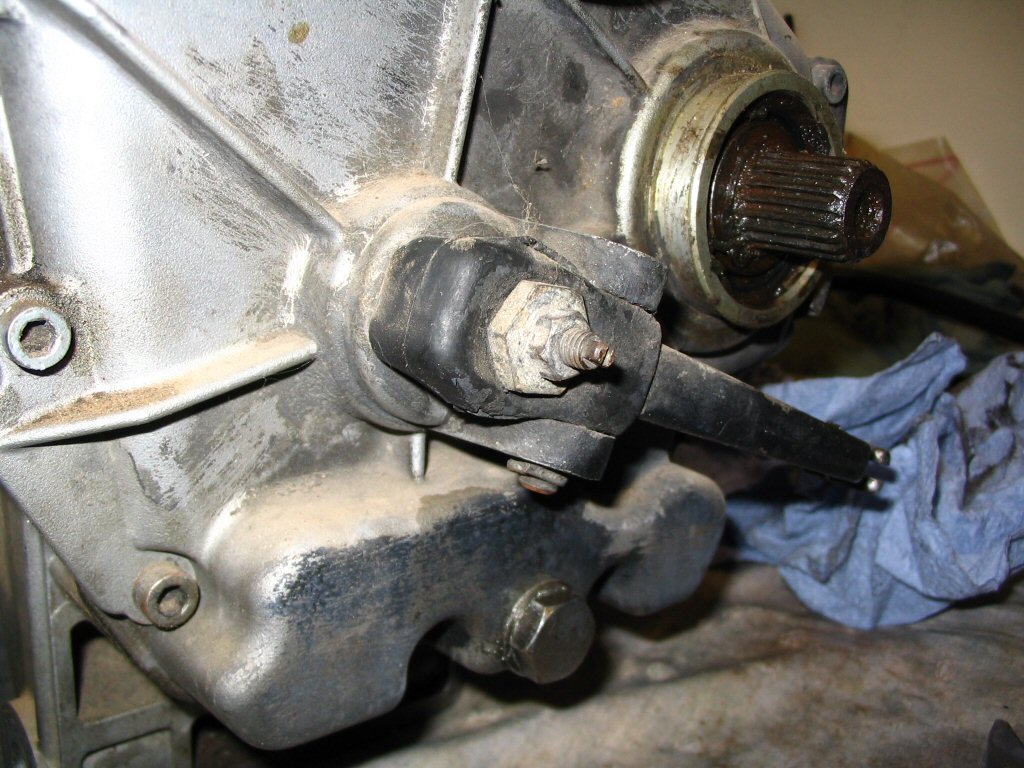
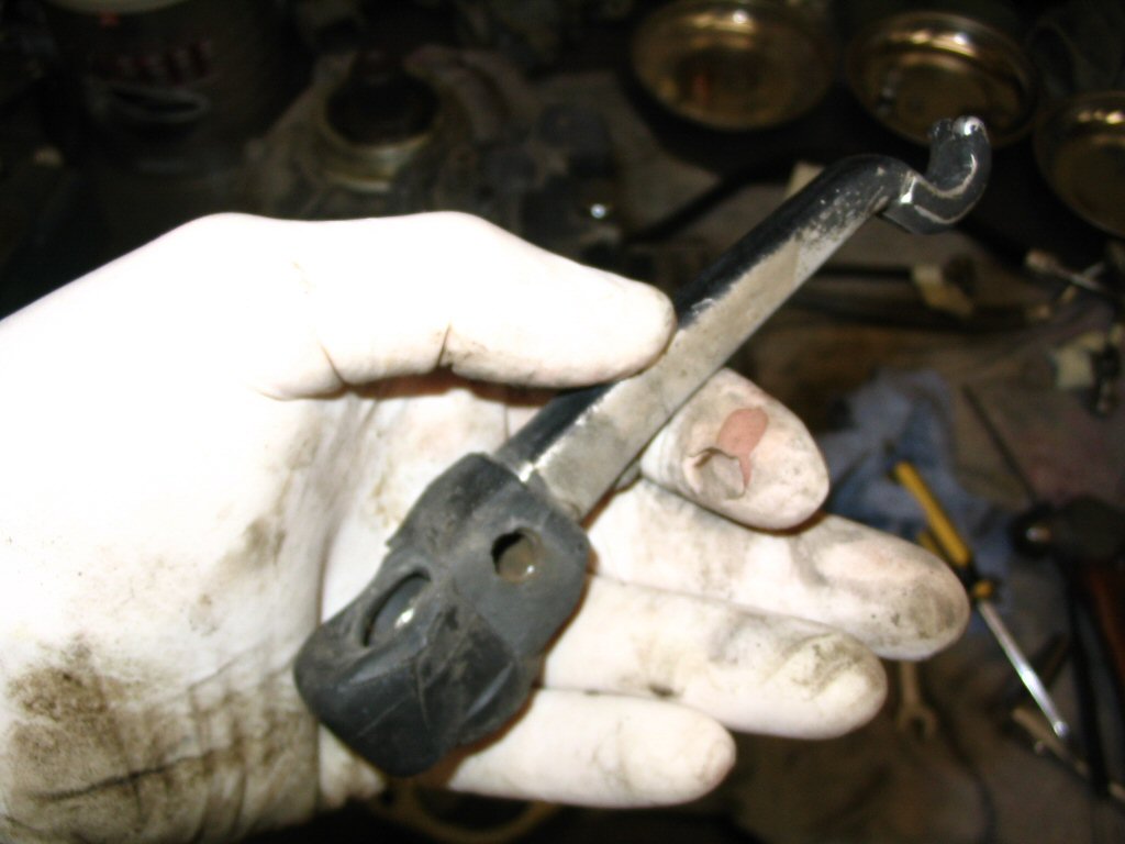
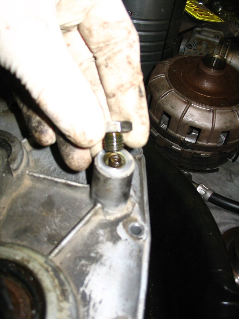
I used the clutch throw out bearing adjustment nut at the rear of the transmission to take the pressure off of the clutch and intermediate plates.
Photo courtesy of Gregory Bender.
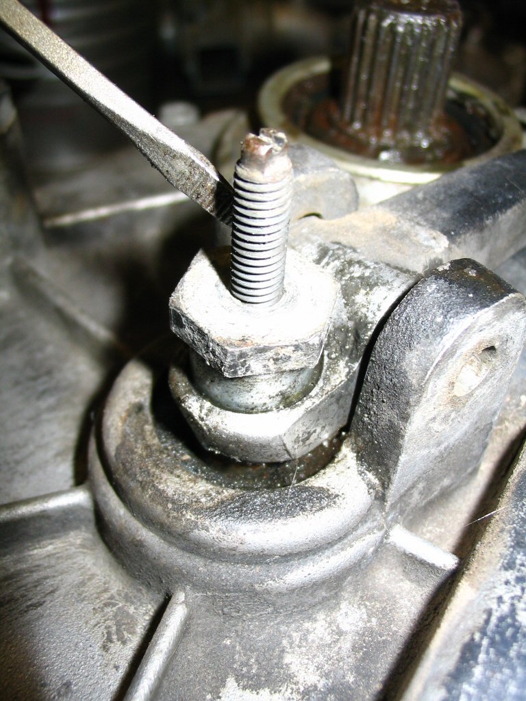
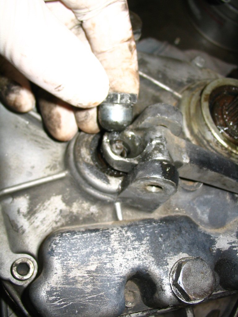
First, remove the smaller jam nut from the back of the transmission.
Photo courtesy of Gregory Bender.
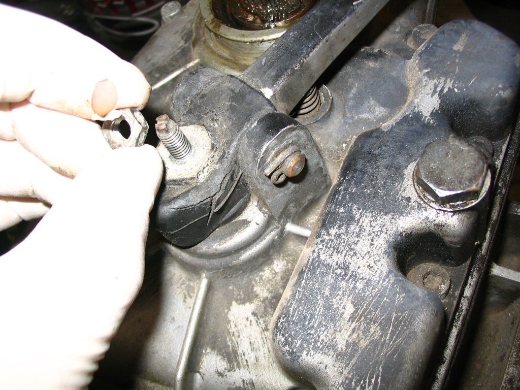
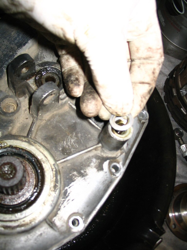
I also removed the adjustment nut and the lever so I could clean and lubricate the threads. Also, I wanted to remove the rubber boot from the lever so it would be easier to tighten the adjustment nut.
Photo courtesy of Gregory Bender.
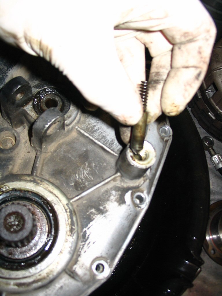
I put the lever back on with the adjustment nut. I then tightened the adjustment nut to compress the clutch springs and take the pressure off of the clutch plates. Go slow here. You may need to completely remove the adjustment nut, then clean and lubricate the threads so that you don't destroy the threads in the process.
Photo courtesy of Gregory Bender.
With the large snap ring removed, you can withdraw all of the clutch and intermediate plates.
Photo courtesy of Gregory Bender.
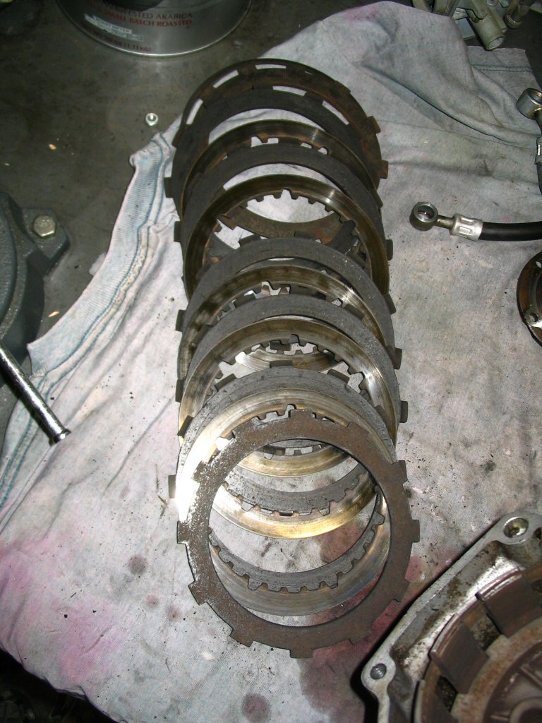
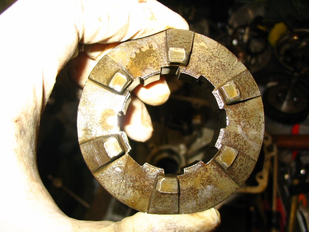
Here is the stack of clutch and intermediate plates. I kept them in the original order throughout cleaning and reassembly. It shouldn't matter, but when reusing used parts I like to error on the side of same-ness.
Photo courtesy of Gregory Bender.
Remove the adjustment nut.
Photo courtesy of Gregory Bender.
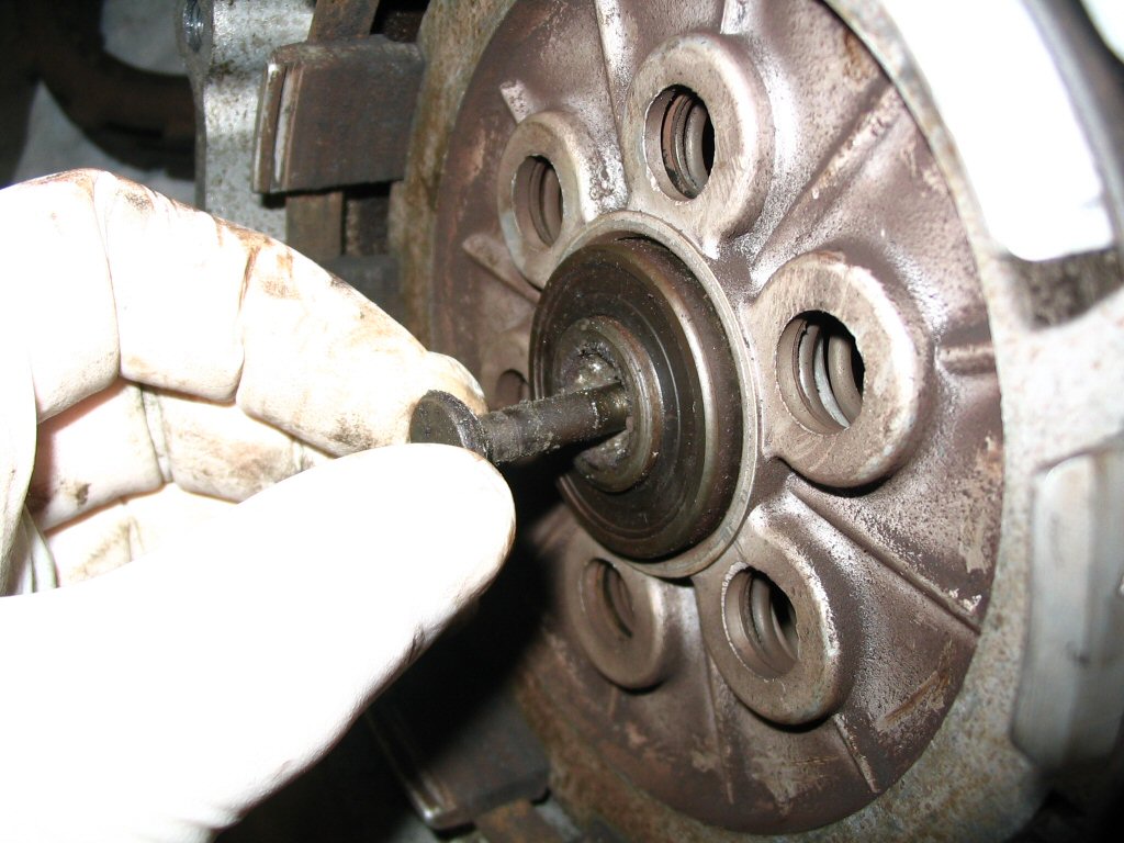
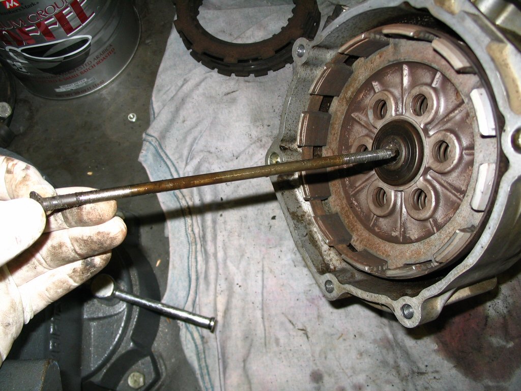
And withdraw the clutch throw out bearing pull rod from the front of the gearbox.
Photo courtesy of Gregory Bender.
Another view of the pull rod being removed.
Photo courtesy of Gregory Bender.
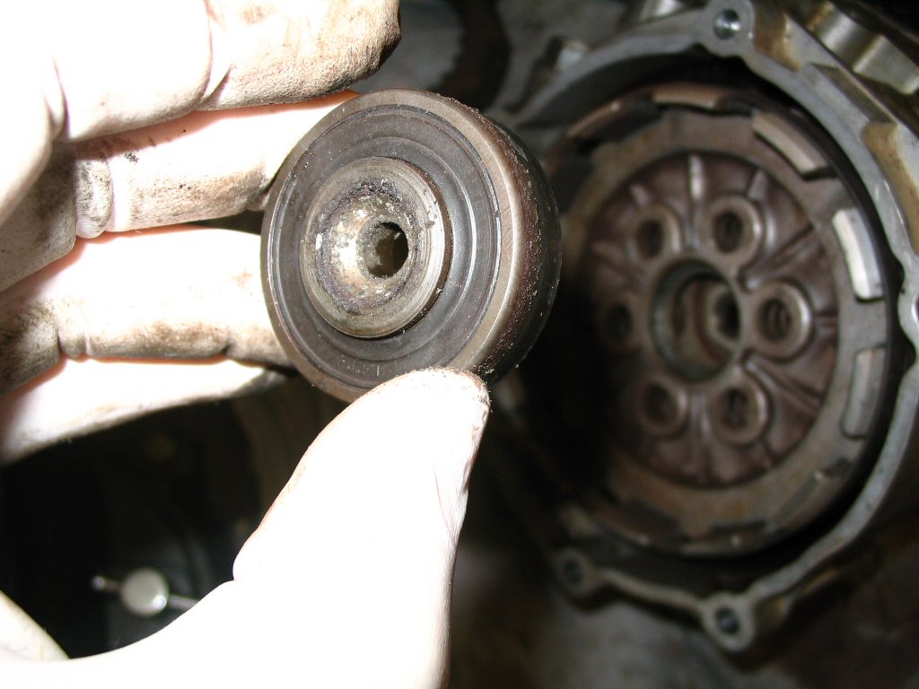
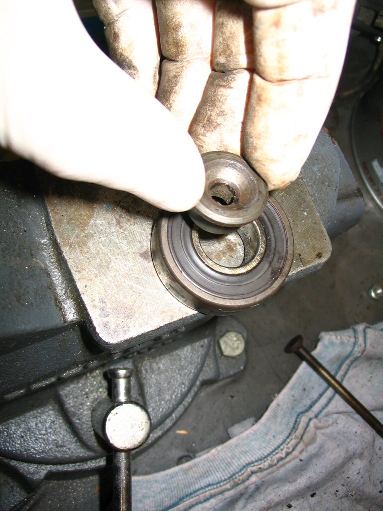
The throw out bearing (MG# 92204217) came out easily.
Photo courtesy of Gregory Bender.
Another view of the throw out bearing (MG# 92204217) being removed.
Photo courtesy of Gregory Bender.
This is the special insert that fits inside the throw out bearing (MG# 92204217).
Photo courtesy of Gregory Bender.
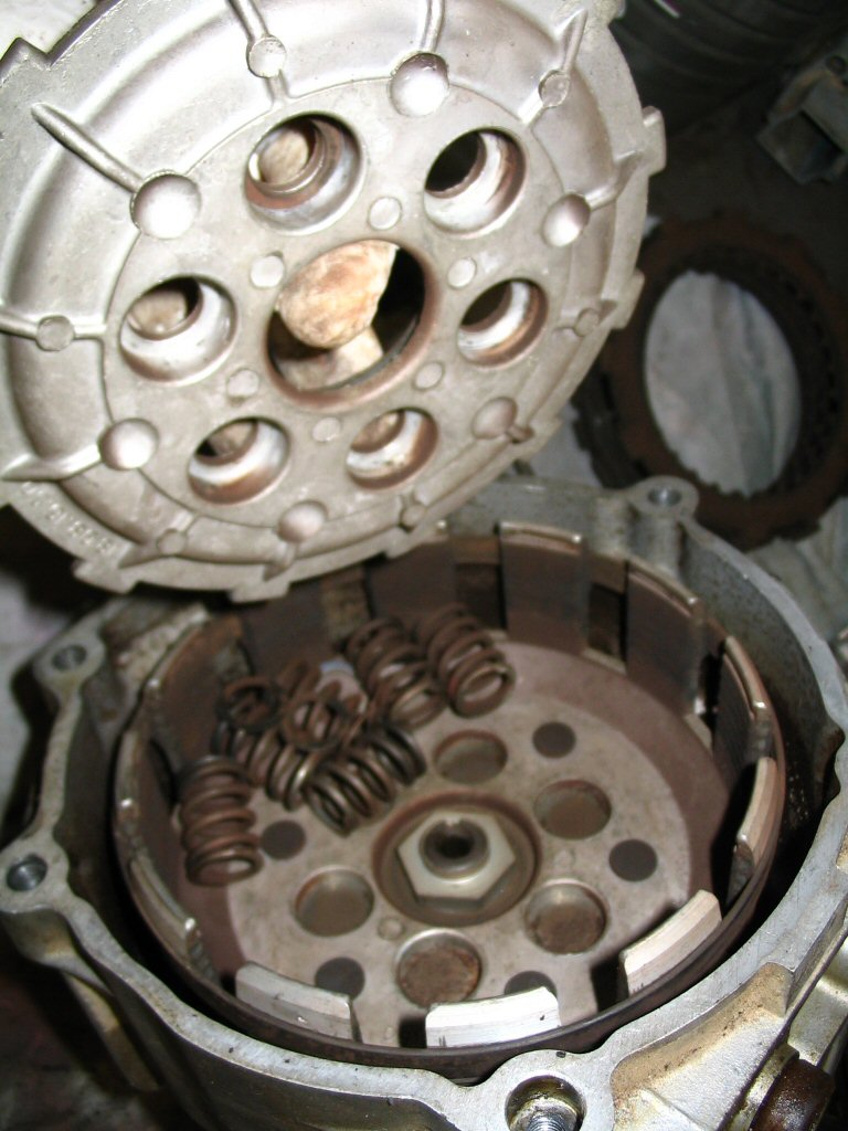
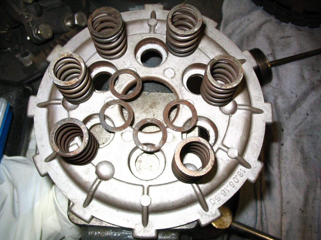
Remove the pressure plate. Note the 6 springs and the thin washers. The washers fit within the recesses of the pressure plate, not in the basket.
Photo courtesy of Gregory Bender.
Another view of the pressure plate with thin washers and springs.
Photo courtesy of Gregory Bender.
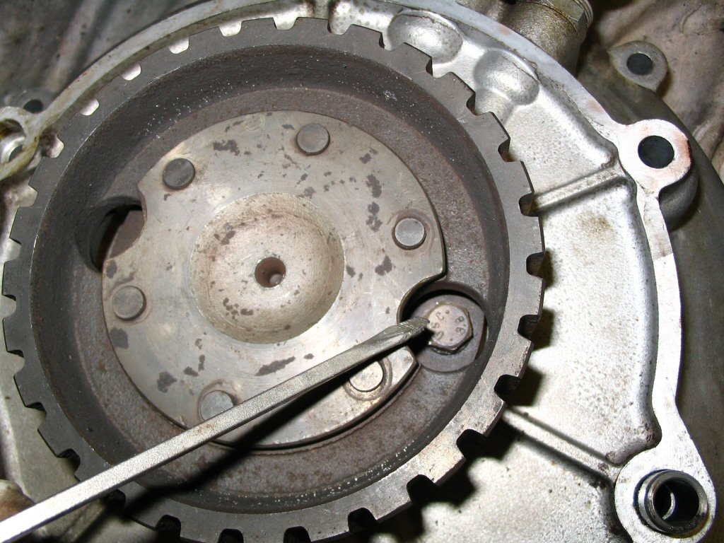
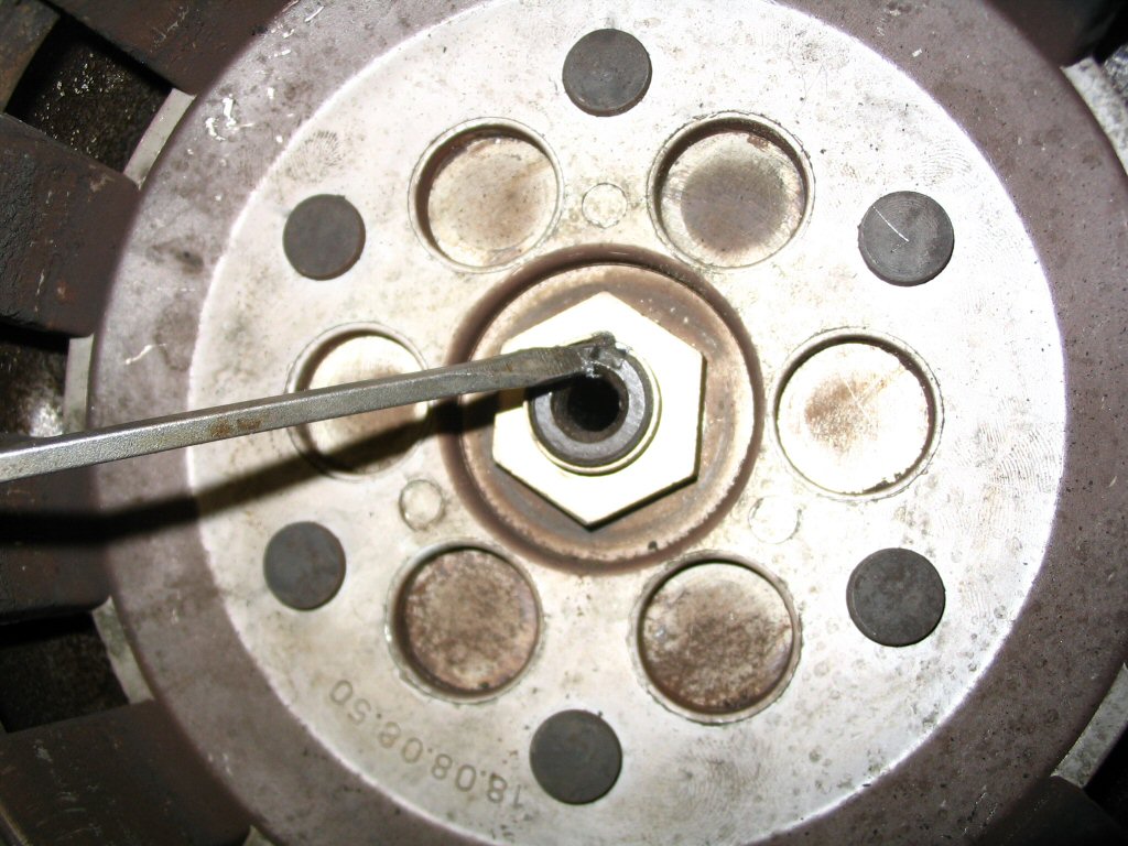
The lip of the nut will have been peened into the slot in the shaft. Pry the peened portion away from the shaft.
Photo courtesy of Gregory Bender.
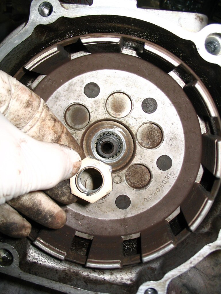
And remove the nut.
Photo courtesy of Gregory Bender.
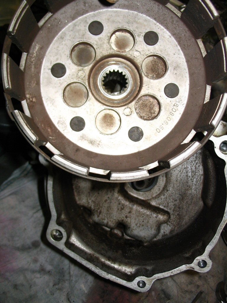
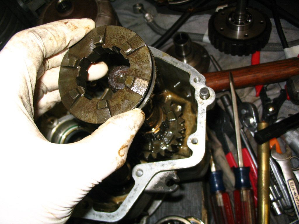
Remove the basket. Mine came off pretty easily without much fuss.
Photo courtesy of Gregory Bender.
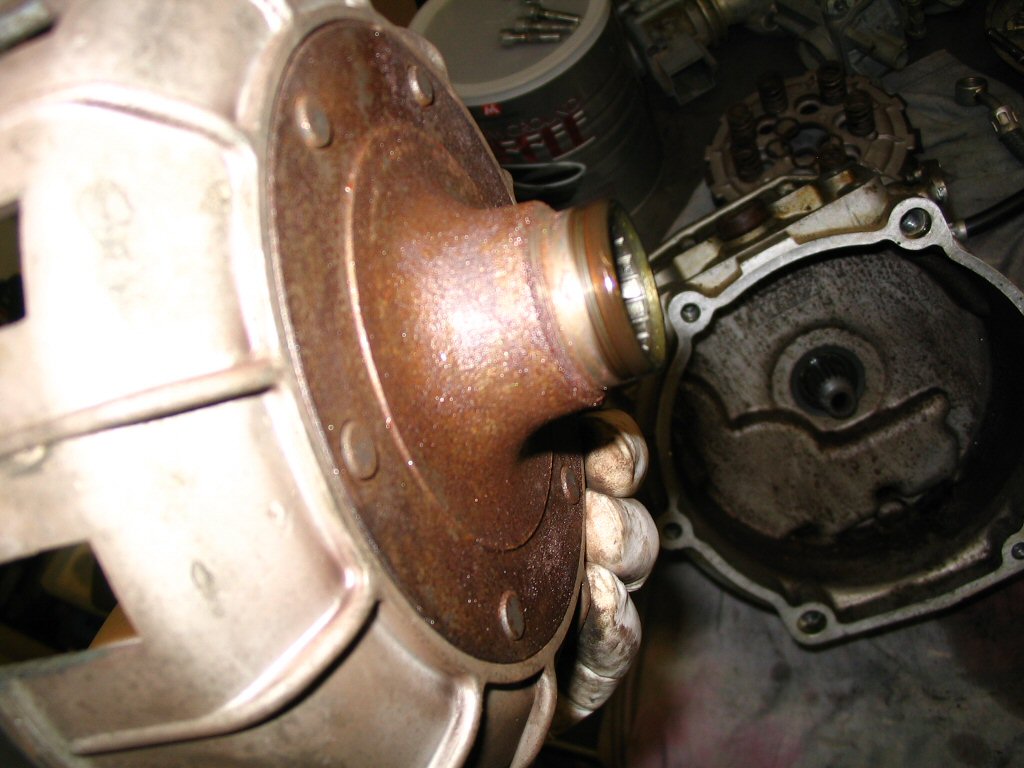
A seal runs on this surface, be sure to clean and dress it properly.
Photo courtesy of Gregory Bender.
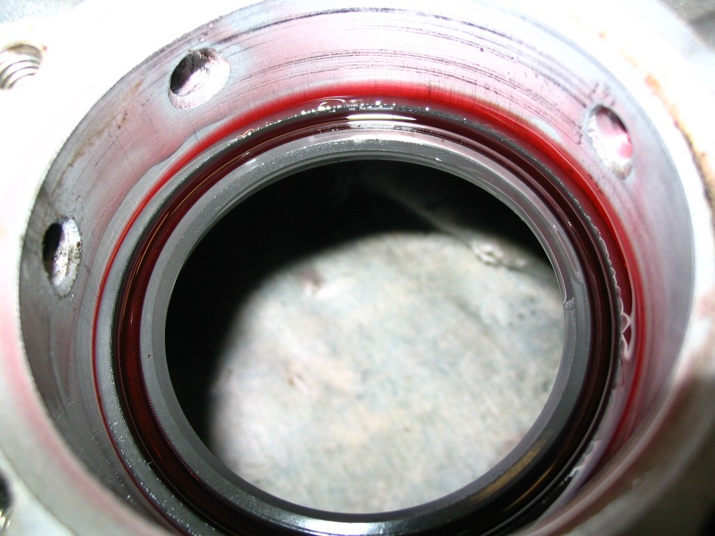
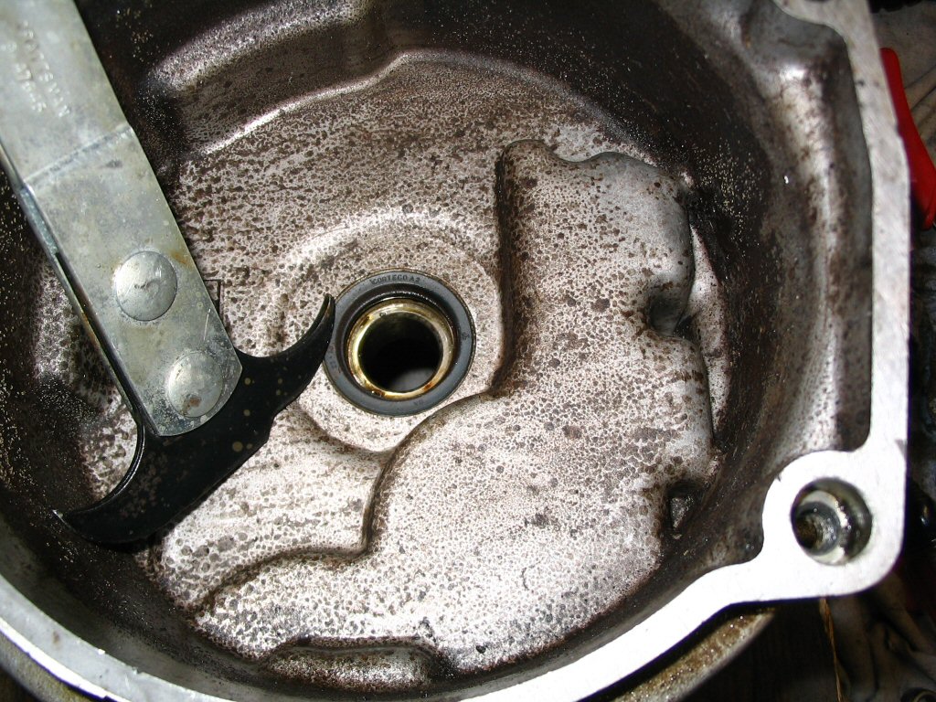
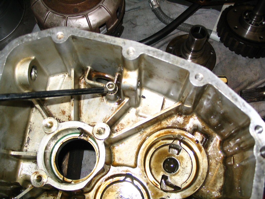
With the clutch basket removed, you can now see the front of the gearbox and the seal.
Photo courtesy of Gregory Bender.
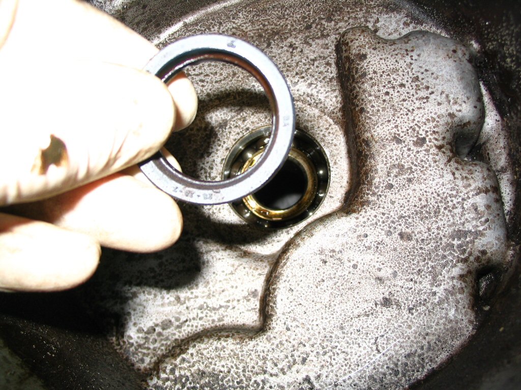
Note the seal (MG# 90402838).
Photo courtesy of Gregory Bender.
And the O-ring (MG# 90706188). Before we remove the seal or O-ring (MG# 90706188), however, lets disassemble the gear box.
Photo courtesy of Gregory Bender.
Gear box disassembly
With the clutch basket removed from the gear box, we can now disassemble the gear box.
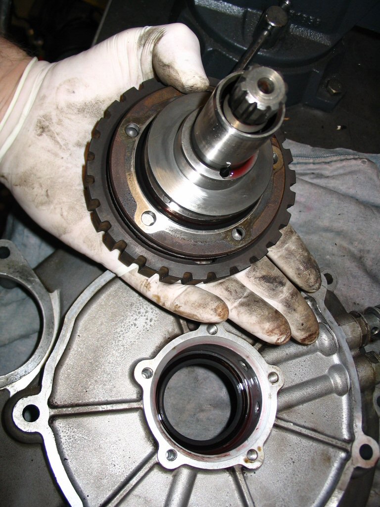
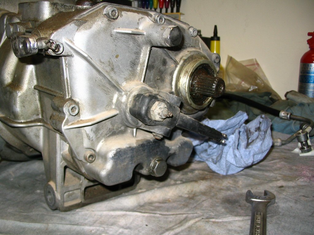
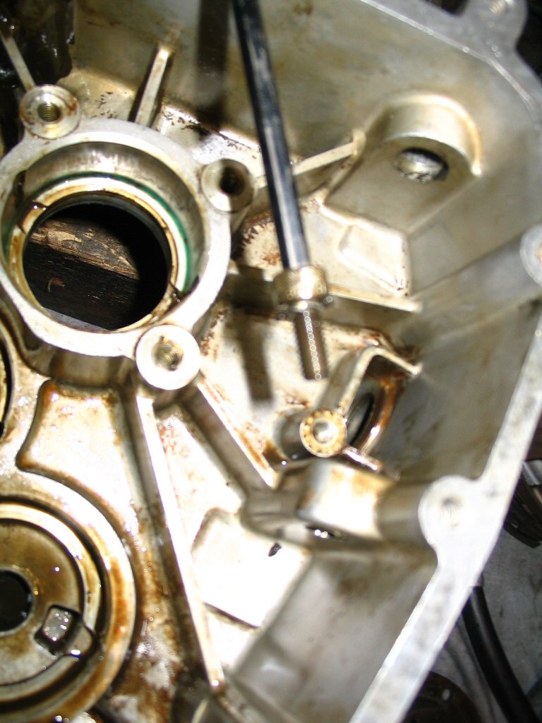
A view of the rear of the transmission.
Photo courtesy of Gregory Bender.
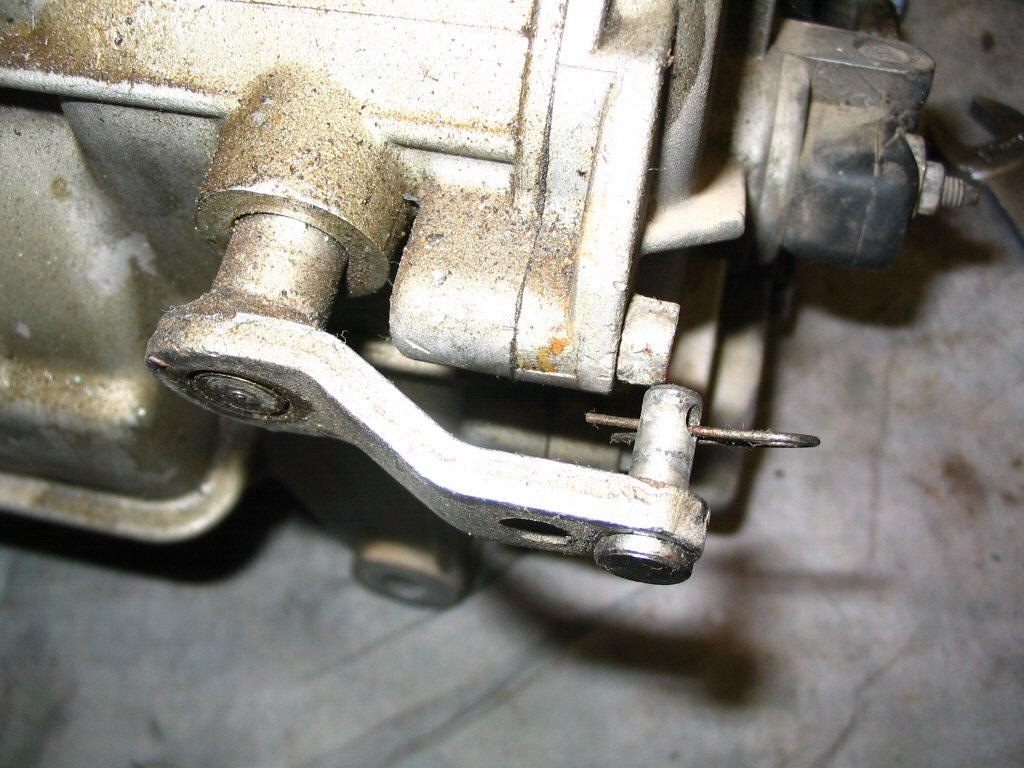
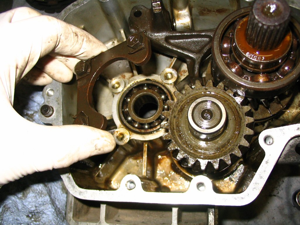
Here is the shift arm and how it was originally positioned.
Photo courtesy of Gregory Bender.
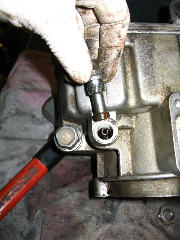
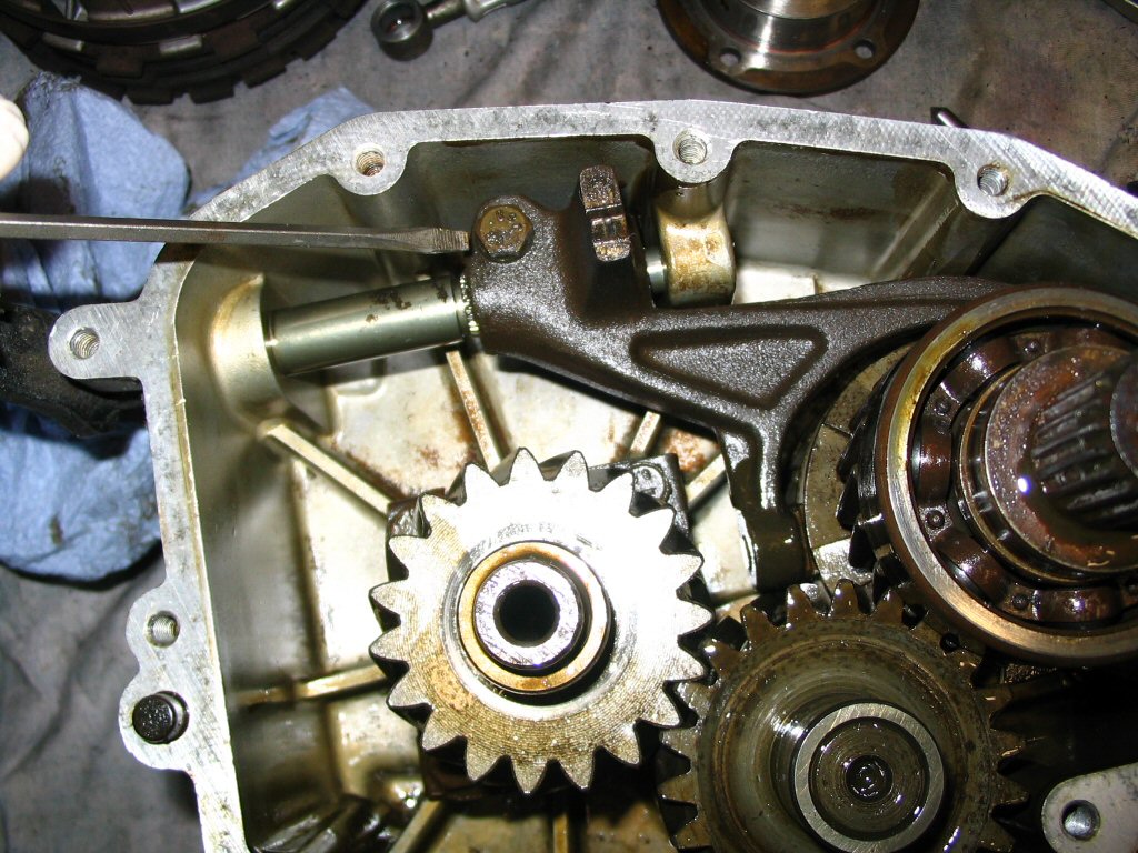
We'll start disassembling the gear box by removing the speedometer drive gear.
Photo courtesy of Gregory Bender.
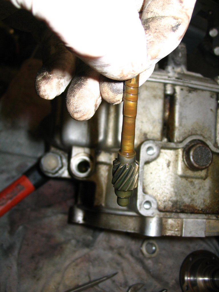
Remove the gear drive.
Photo courtesy of Gregory Bender.
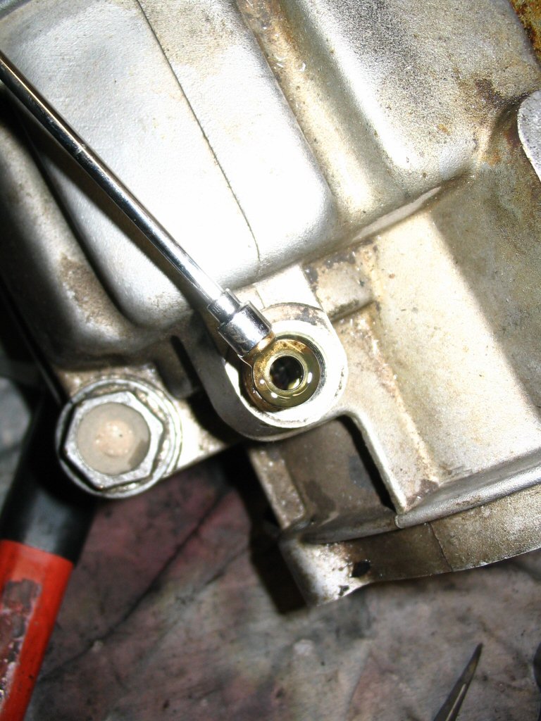
And use a small magnet to withdraw the hardened steel washer down inside that hole.
Photo courtesy of Gregory Bender.
Set the transmission up on end. Remove the spring loaded plug that holds gear selector pawl in place.
Photo courtesy of Gregory Bender.
Remove the crush washer.
Photo courtesy of Gregory Bender.
Withdraw the spring and selector pawl.
Photo courtesy of Gregory Bender.
Remove the drain plug along with its crush washer.
Photo courtesy of Gregory Bender.
Remove all of the bolts that secure the cover to the case.
Photo courtesy of Gregory Bender.
Here is the snap ring on the output shaft.
Photo courtesy of Gregory Bender.
Remove the snap ring (this could also be removed after the cover is removed).
Photo courtesy of Gregory Bender.
Remove the cover from the case.
Photo courtesy of Gregory Bender.
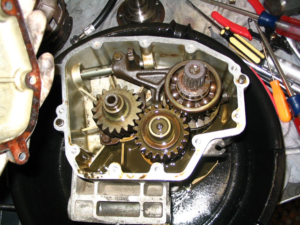
The inside of the cover.
Photo courtesy of Gregory Bender.
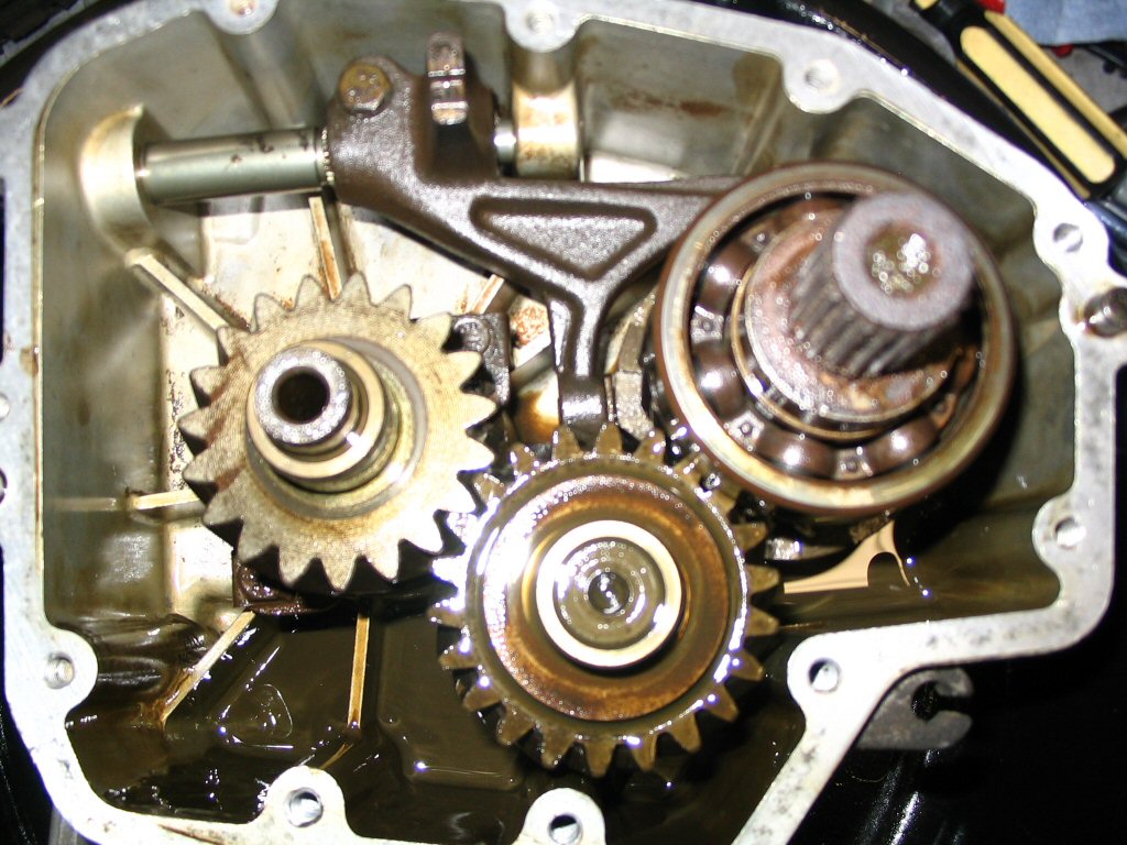
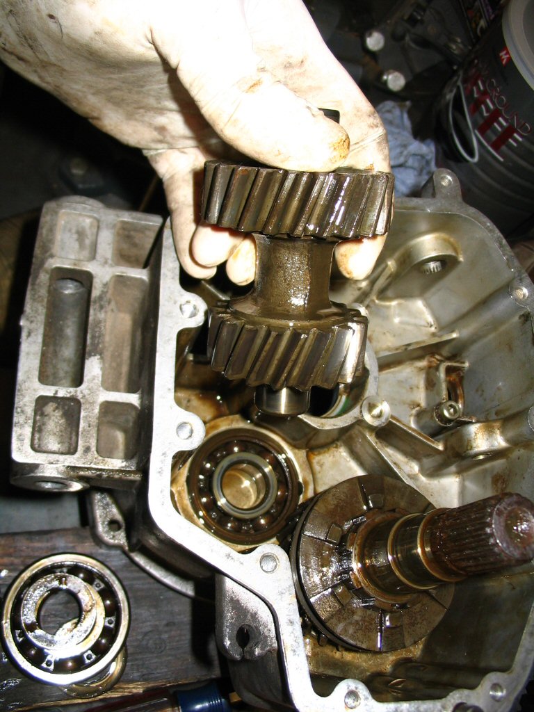
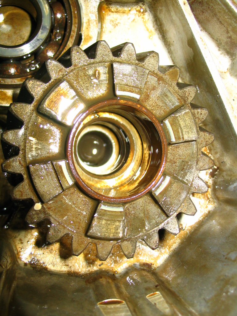
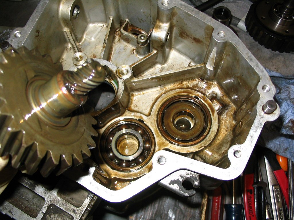
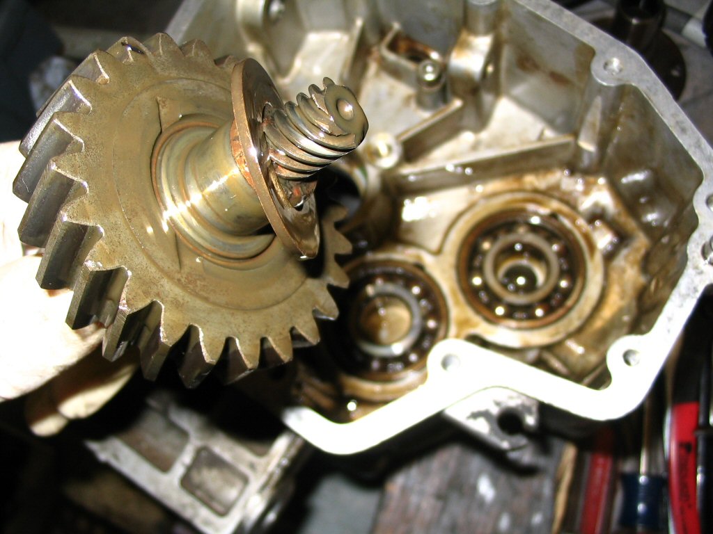
The gears inside the transmission.
Photo courtesy of Gregory Bender.
A closer view.
Photo courtesy of Gregory Bender.
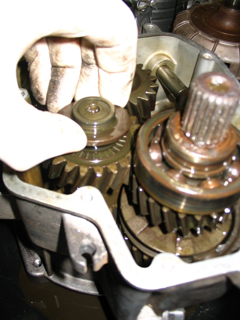
Remove the thrust/shimming washers.
Photo courtesy of Gregory Bender.
There were two placed to the rear of the bearing.
Photo courtesy of Gregory Bender.
Then remove the thrust bearing.
Photo courtesy of Gregory Bender.
There was a single thrust/shimming washer in front of the bearing.
Photo courtesy of Gregory Bender.
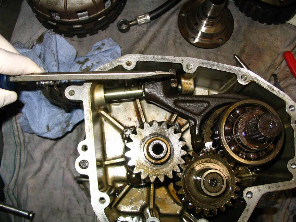
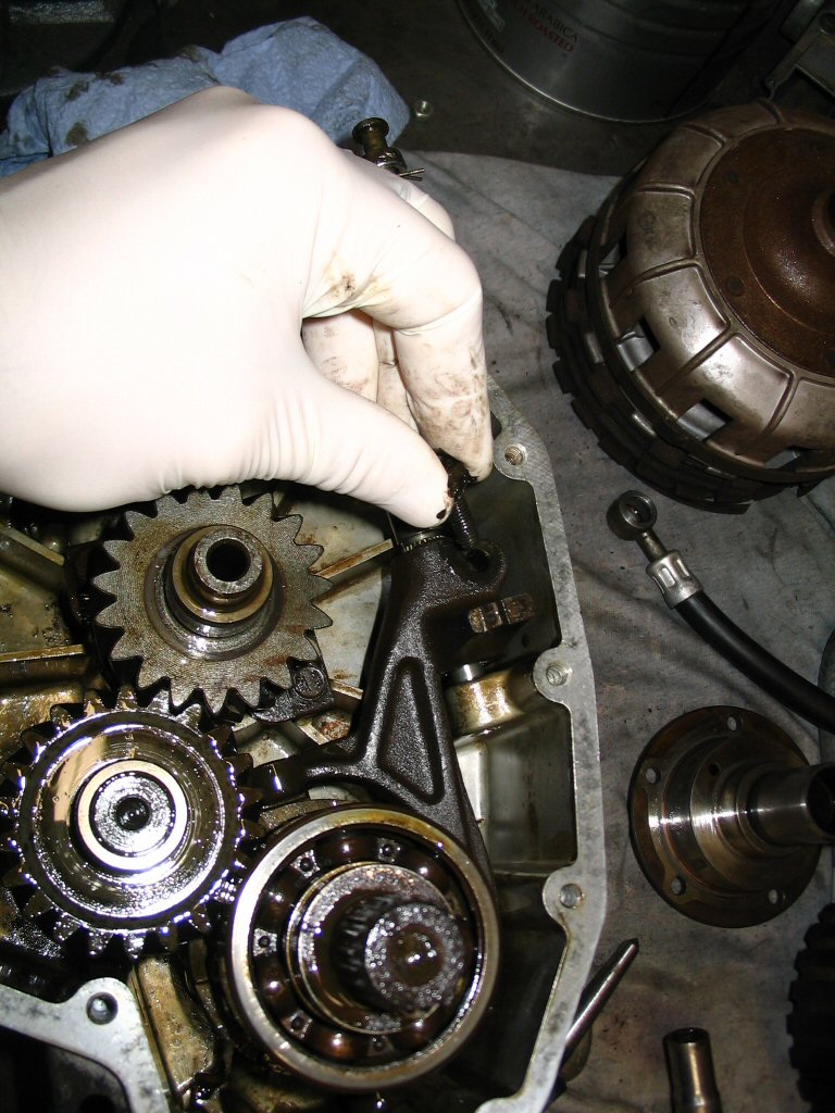
The shift fork assembly is secured to the splined shaft via a pinch bolt.
Photo courtesy of Gregory Bender.
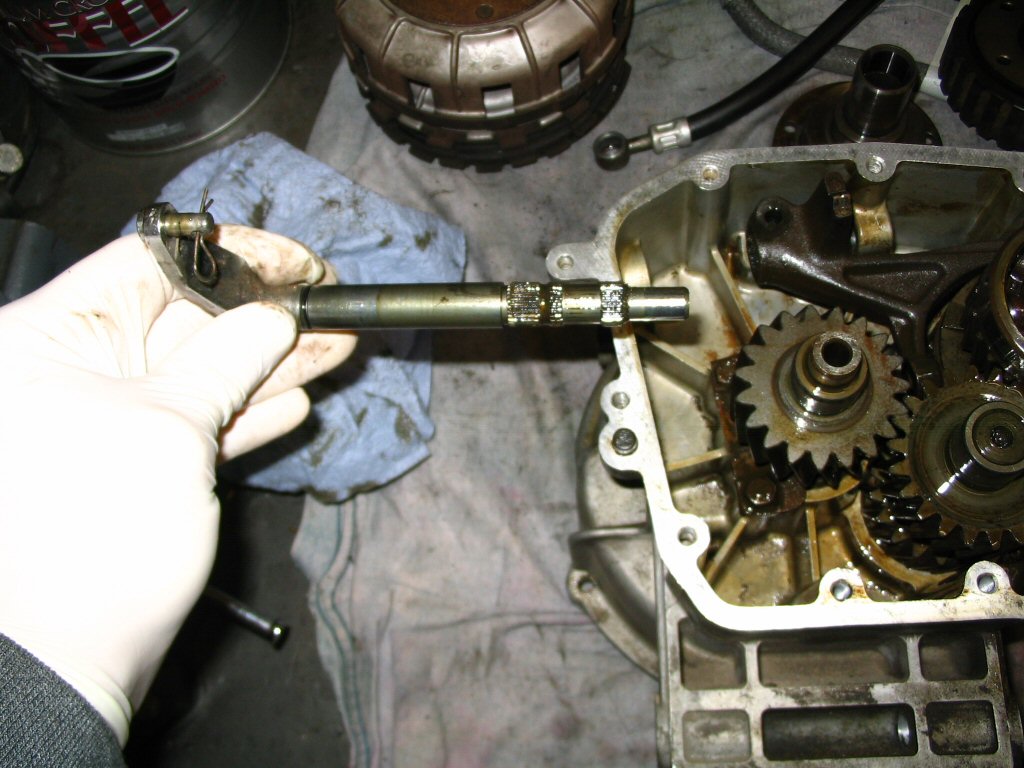
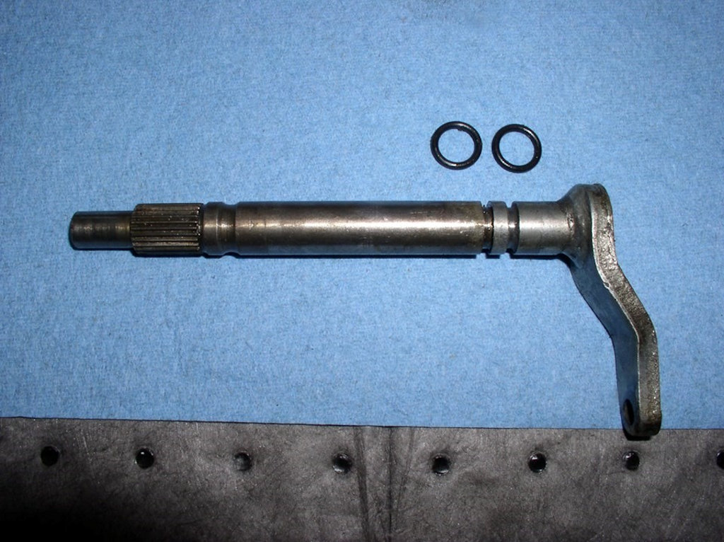
Note the alignment of the external shift arm with the nub on the shift fork assembly.
The input shaft and the O-ring (MG# 90706188) that seals the input shaft and the inner race of the bearing. Note that the O-ring (MG# 90706188) is fit outside of the gearbox, in between the clutch basket and the bearing.
Photo courtesy of Gregory Bender.
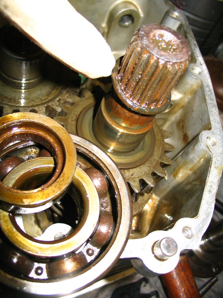
The bearing retainer is secured by three bolts.
Photo courtesy of Gregory Bender.
Remove the three bolts and the bearing retainer.
Photo courtesy of Gregory Bender.
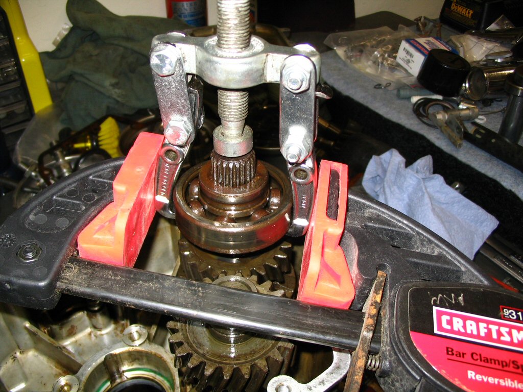
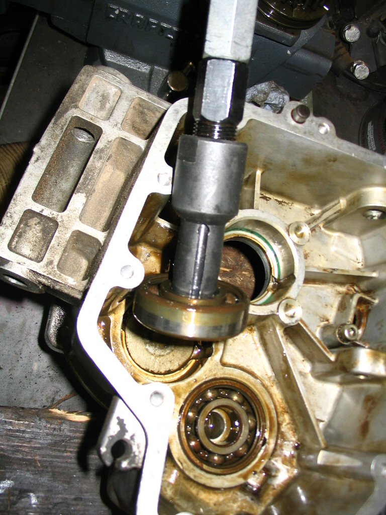
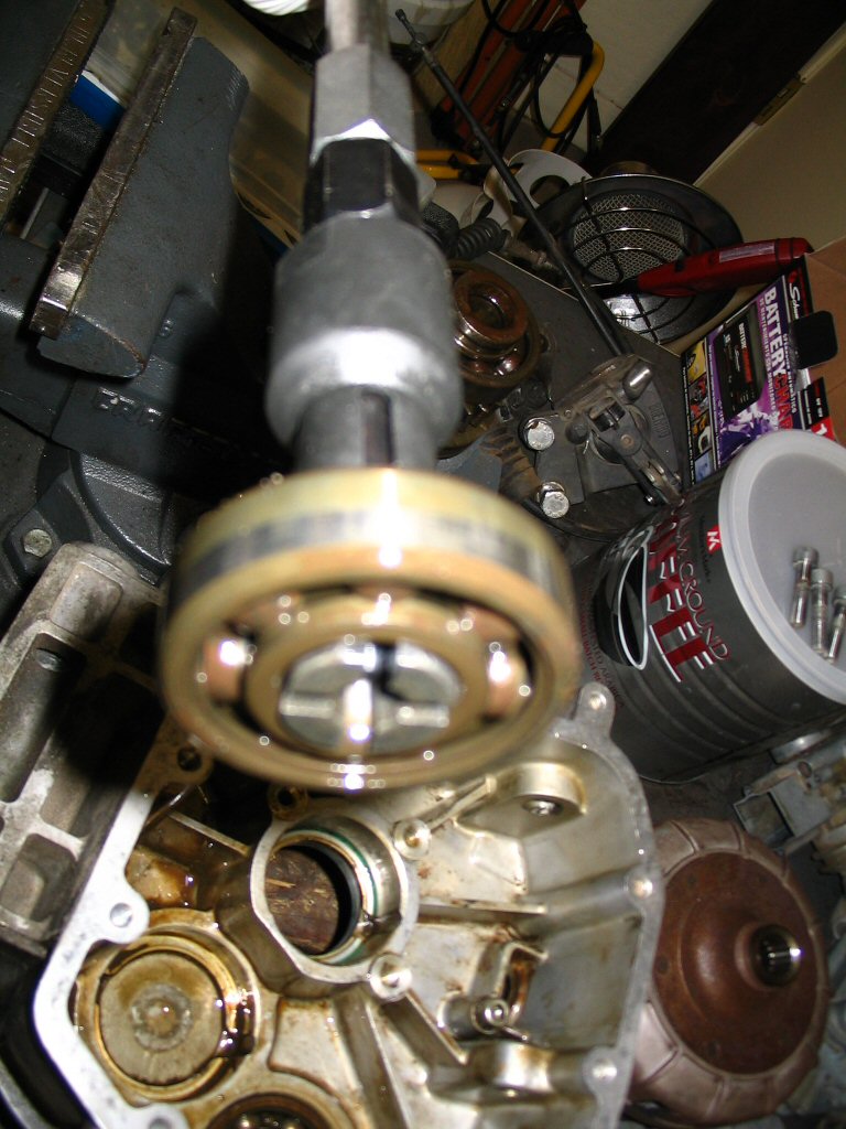
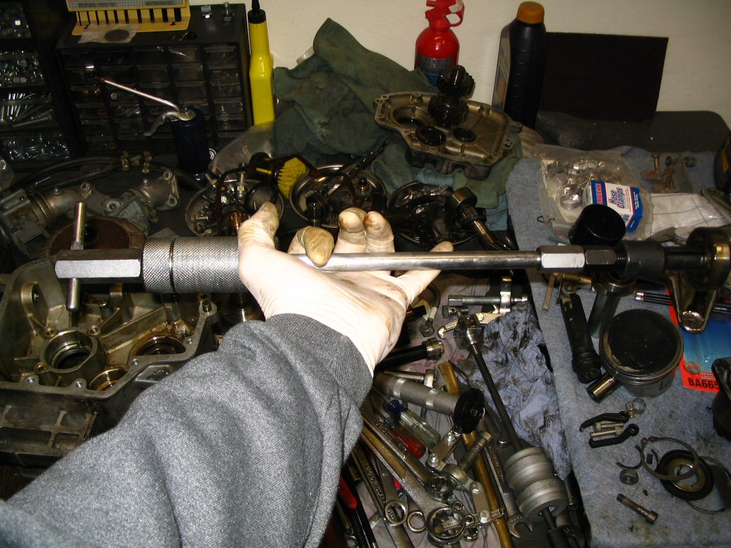
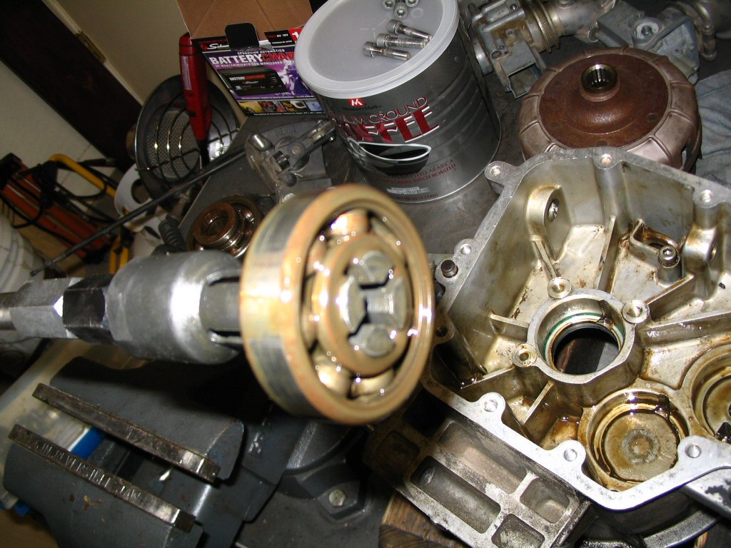
This is the puller arrangement I devised to get the rear bearing and the spacer that the seal runs on off of the output shaft. I chose to pull them off as a unit because (a) the spacer that the seal runs on was stuck in place and (b) I did not want to risk damaging the sealing surface of the spacer that the seal runs on. The clamp was very useful to keep the fingers of the puller lodged under the bearing.
Photo courtesy of Gregory Bender.
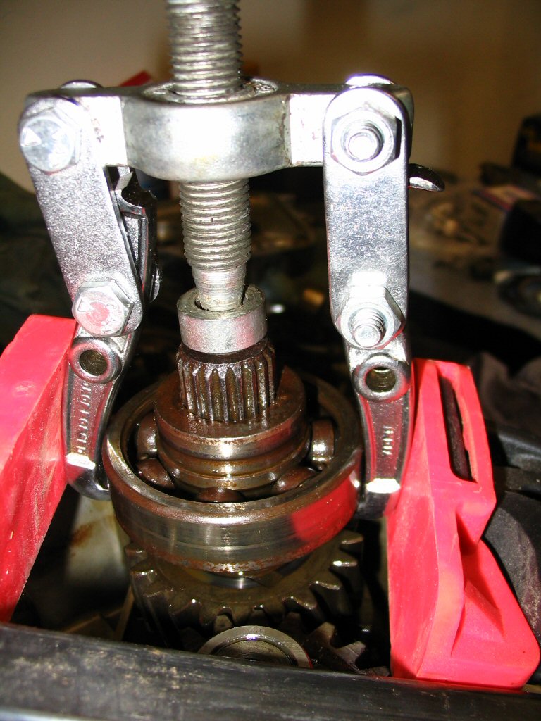
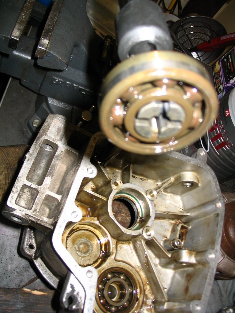
Another view of the puller arrangement.
Photo courtesy of Gregory Bender.
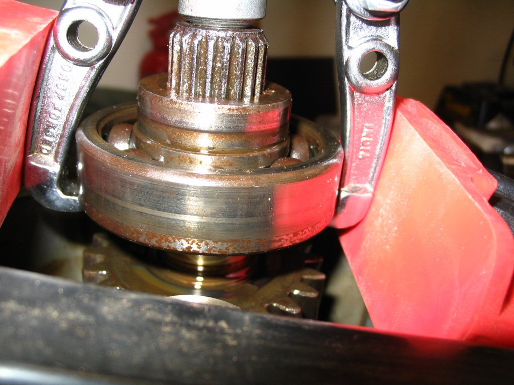
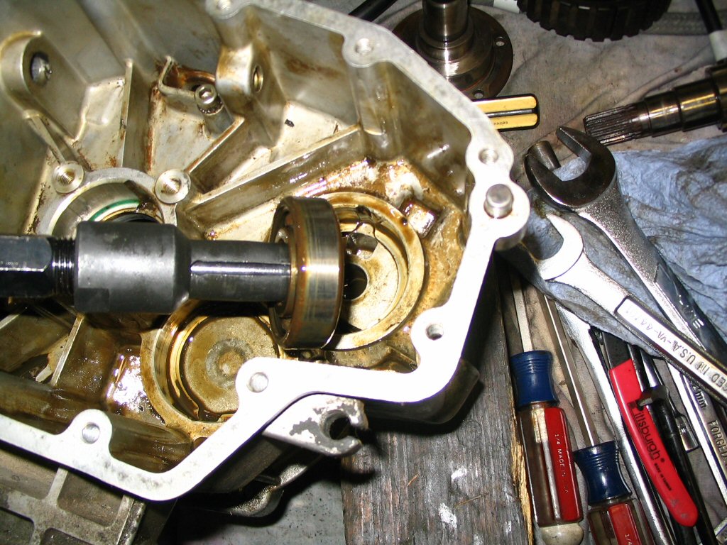
And a close up view of the puller arrangement.
Photo courtesy of Gregory Bender.
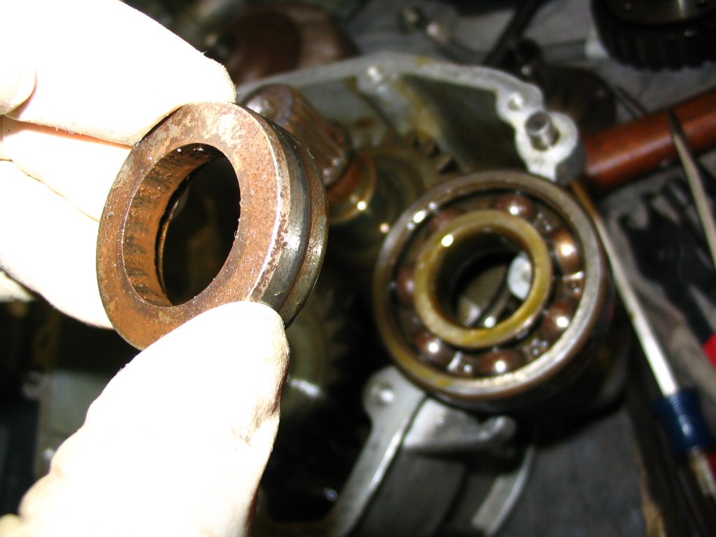
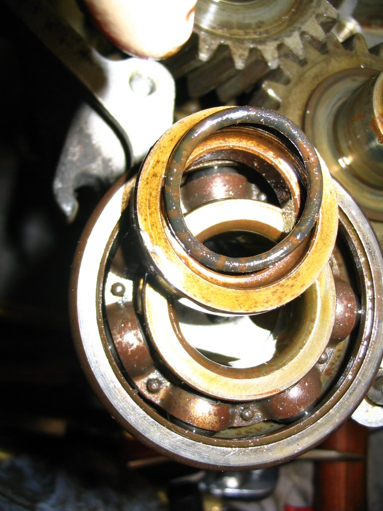
Here is the spacer that the seal runs on. I was able to clean this up nicely.
Photo courtesy of Gregory Bender.
The O-ring (MG# 90706222) remained on the shaft when I pulled the bearing off.
Photo courtesy of Gregory Bender.
Here is where the O-ring (MG# 90706222) fits: within the front recess of the spacer that the seal runs on.
Photo courtesy of Gregory Bender.
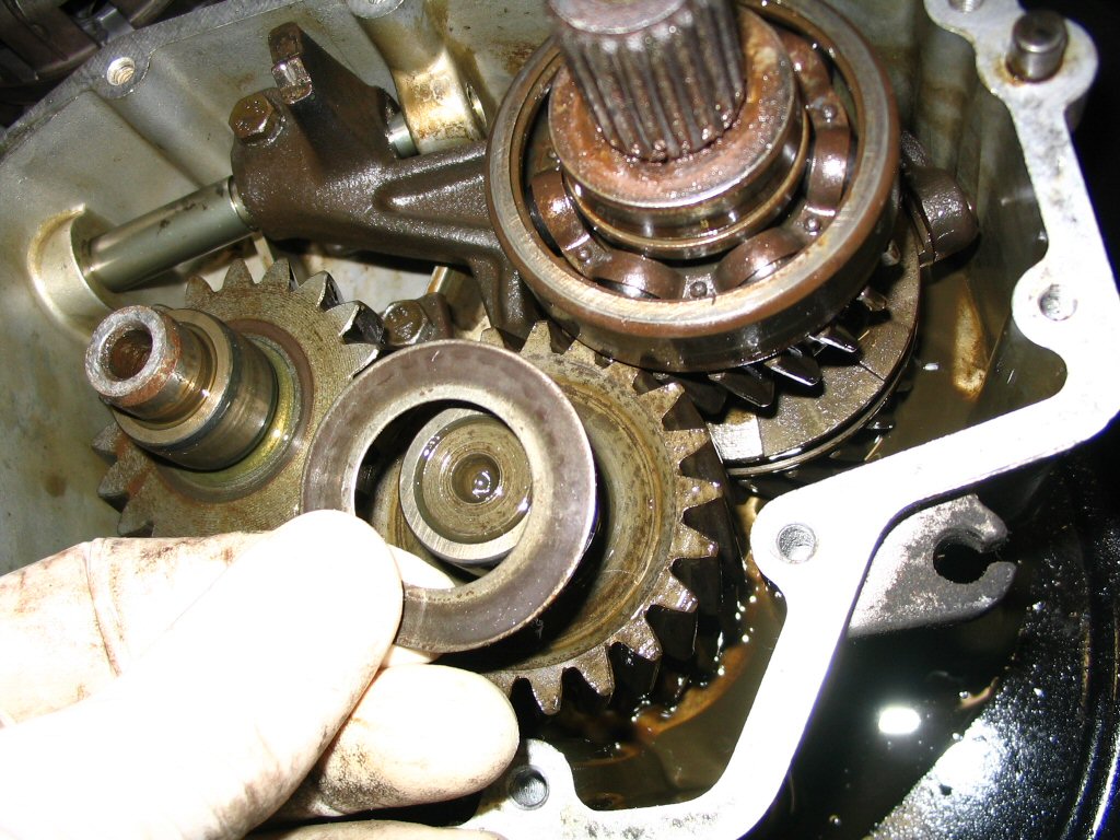
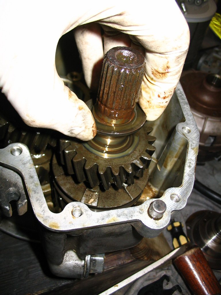
Remove the shimming washer.
Photo courtesy of Gregory Bender.
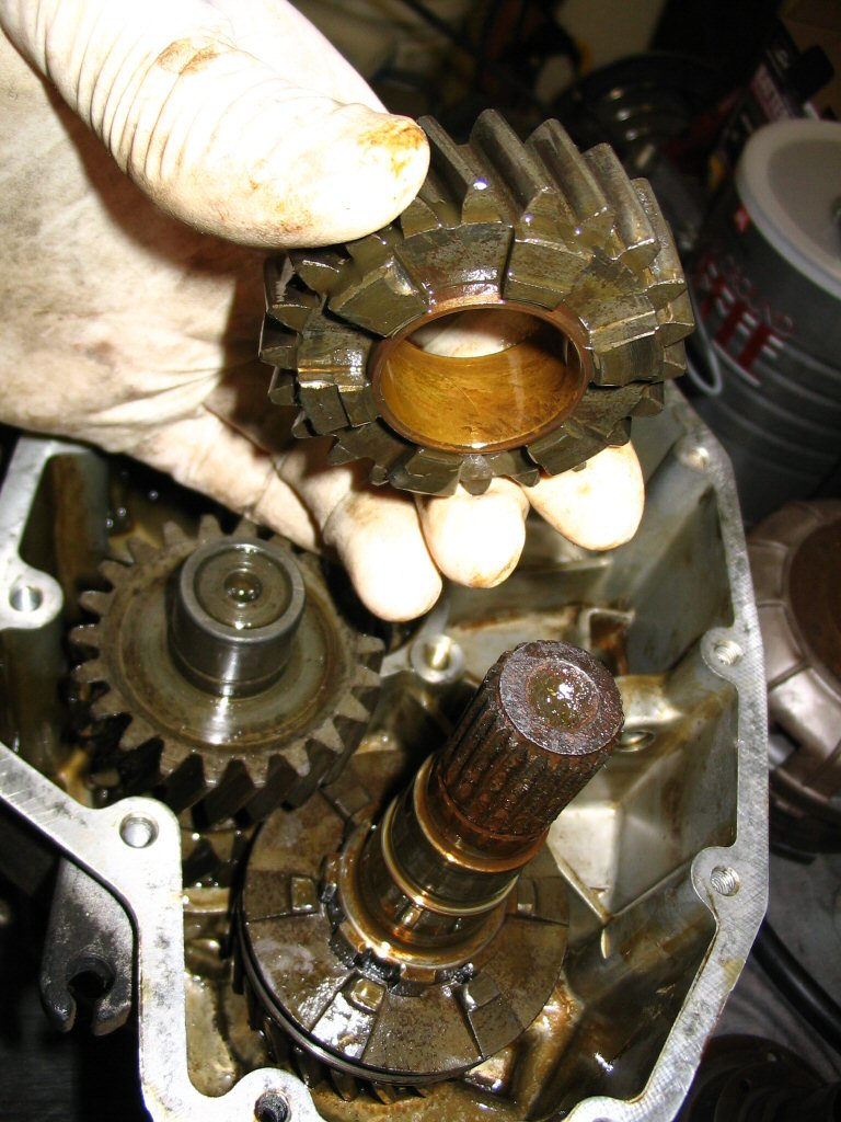
Remove the normal speed gear.
Photo courtesy of Gregory Bender.
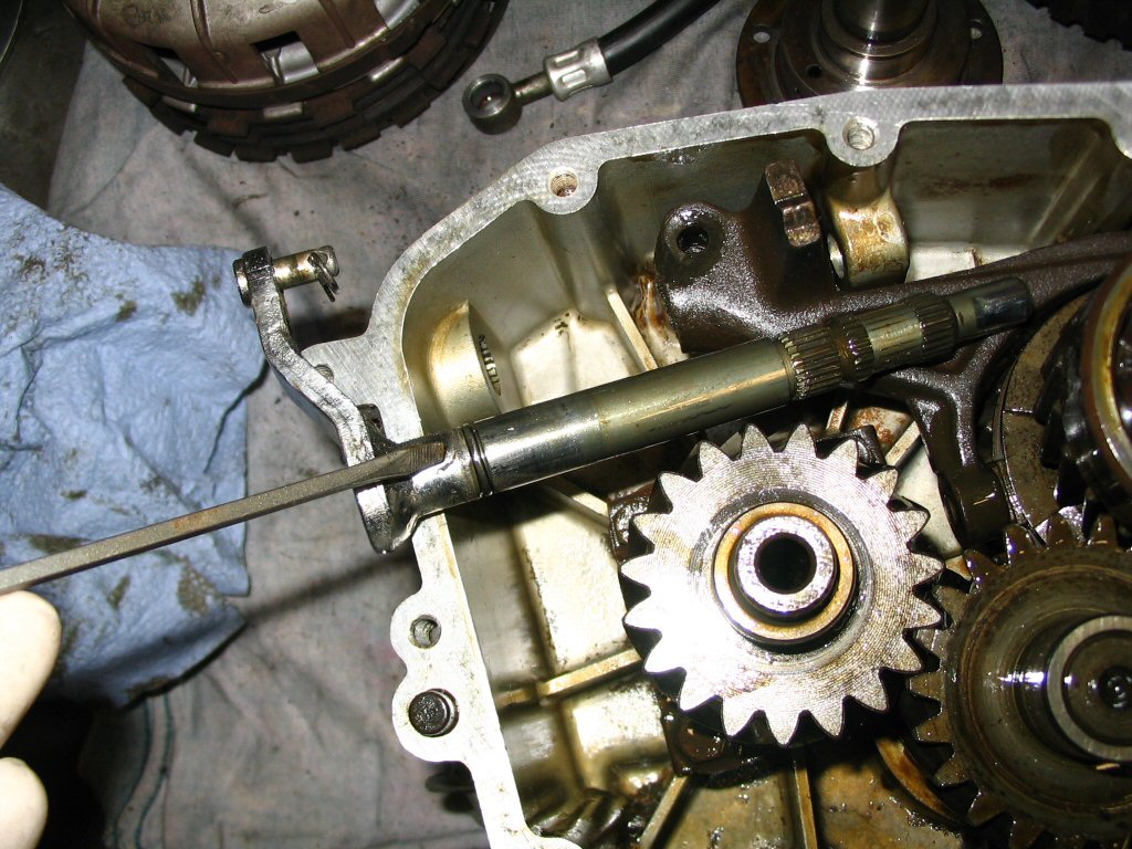
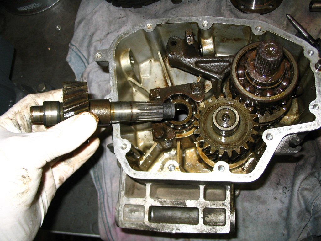
Now the main shaft is easily removed from the front bearing.
Photo courtesy of Gregory Bender.
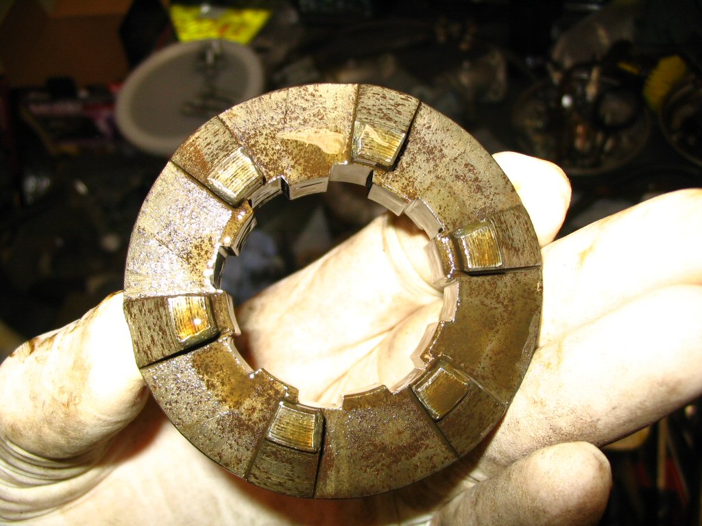
Remove the shift sleeve. Note which side face rearward and which side faced frontward. The shift sleeve can be reversed to double the life of the engagement dogs.
Photo courtesy of Gregory Bender.
Note how one side of the engagement dogs is rounded. This is what happens when convert transmissions are shifted at speed. They should always be shifted when the machine is not in motion.
Photo courtesy of Gregory Bender.
A view of the other side of the shift sleeve.
Photo courtesy of Gregory Bender.
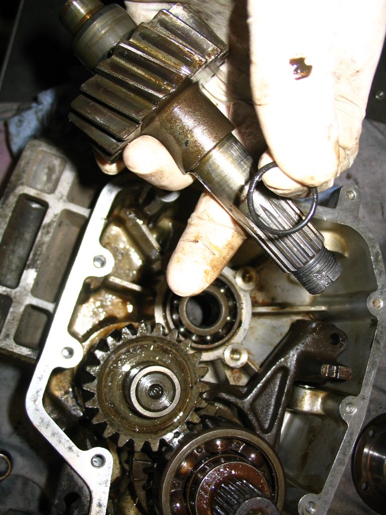
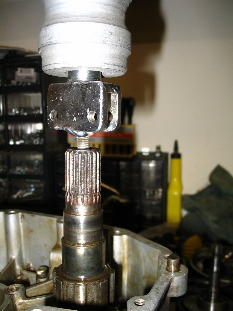
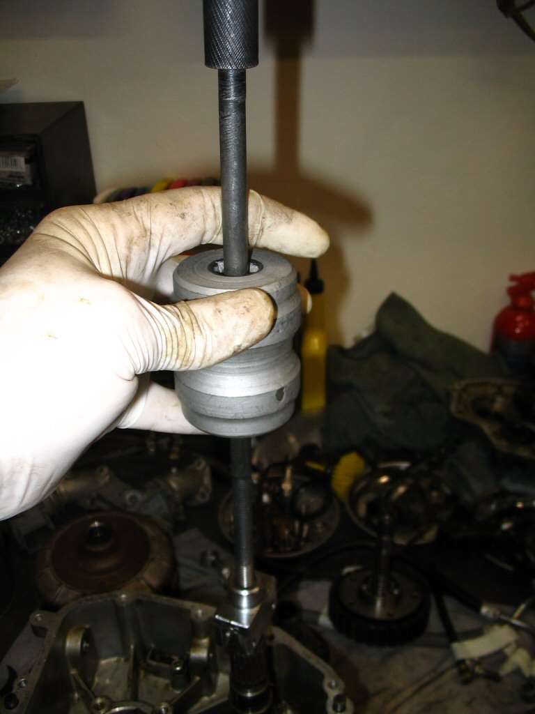
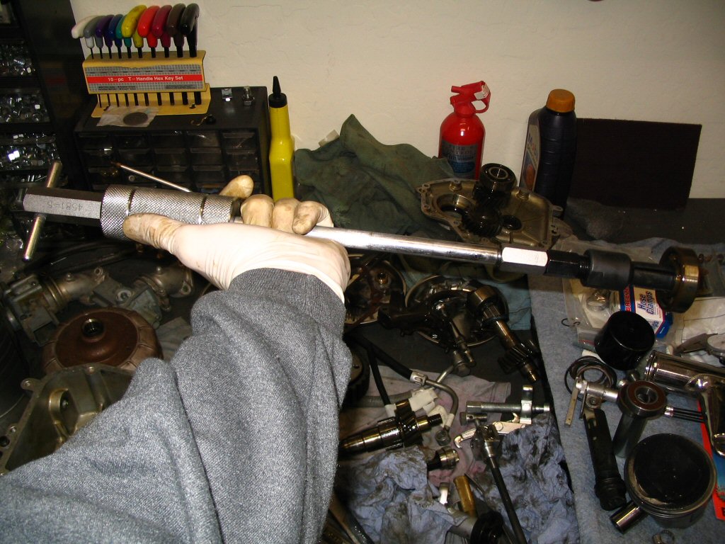
The output shaft was pretty well stuck in the front bearing and there is no good way to pry it out. So, I welded up a small adapter for my slide hammer so that I could pull the shaft out. The end of the shaft is already threaded for 8 mm × 1.25 mm threads, so all I needed to do was weld a bolt onto the end of an adapter. This worked a treat!
Photo courtesy of Gregory Bender.
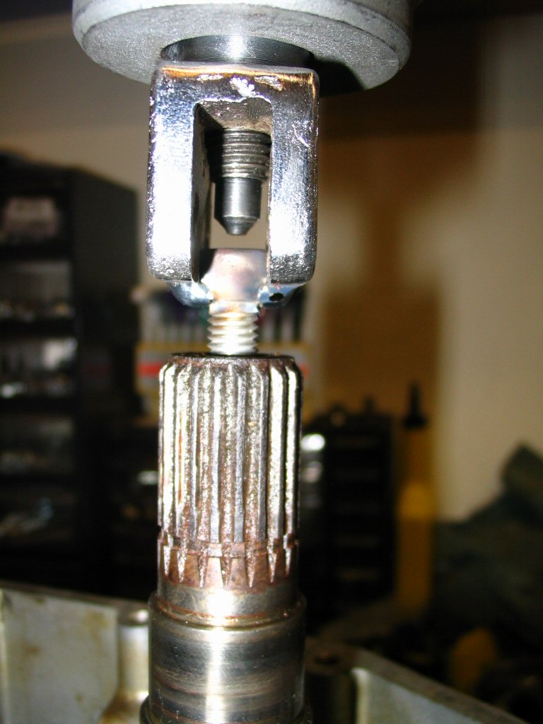
Another view of the puller I used to withdraw the output shaft from the bearing.
Photo courtesy of Gregory Bender.
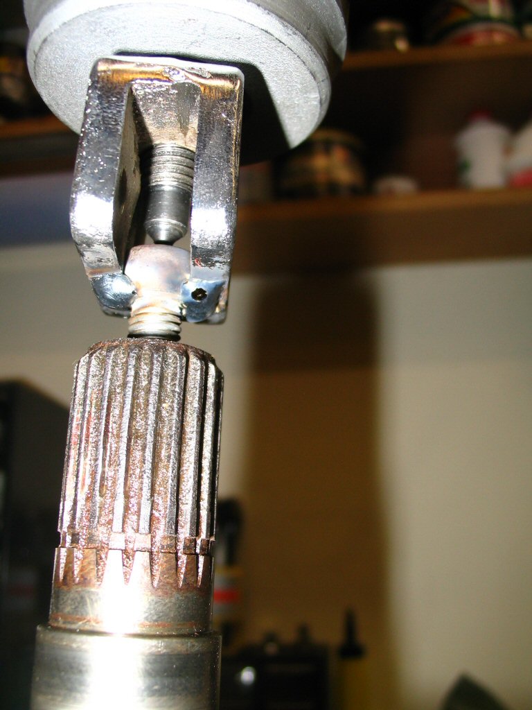
Another view of the puller I used to withdraw the output shaft from the bearing.
Photo courtesy of Gregory Bender.
Another view of the puller I used to withdraw the output shaft from the bearing.
Photo courtesy of Gregory Bender.
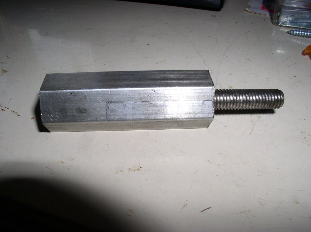
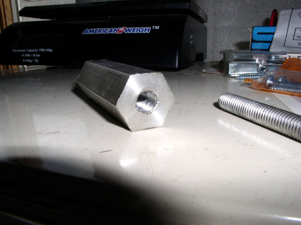
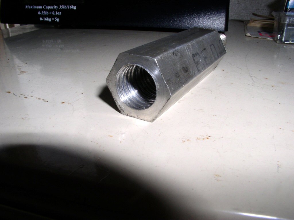
Charlie Mullendore of Antietam Classic Cycle sent me this photo of the adapter he made for his puller. In Charlie's own words: I didn't have any steel hex (or round) on hand so just used 3⁄4 inch aluminum hex and it worked just fine. One end is drilled and tapped 9⁄16 inch-12, the other 8 mm - 1.25 mm. The 9⁄16 inch end I screwed onto the OTC blind bearing puller shaft on the handle end (the handle isn't pinned into place, the other end is) and I cut the head off an 8 mm bolt for the output shaft end. Worked perfectly.
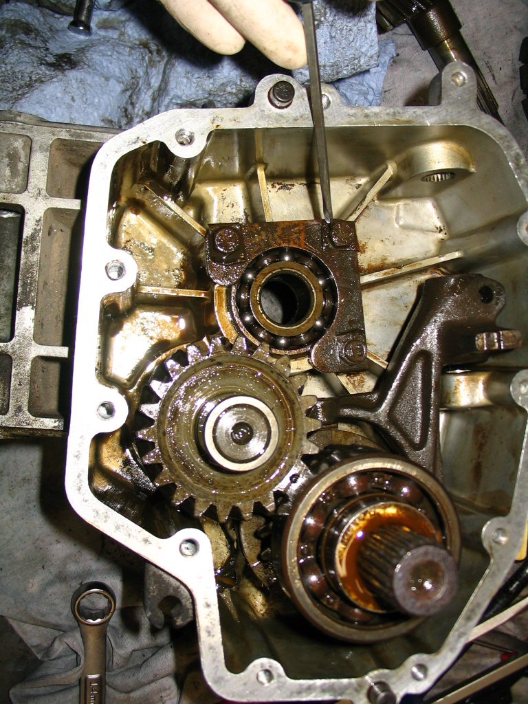
Here is the low speed gear back in place on the output shaft (layshaft). Note the shimming washer is still on top of the bearing.
Photo courtesy of Gregory Bender.
The shimming washer is now in place on the output shaft (layshaft).
Photo courtesy of Gregory Bender.
Use a seal puller to remove the seal from the case. Be careful not to gouge the case or else you'll have trouble getting the next seal installed and you may have trouble with it sealing properly.
Photo courtesy of Gregory Bender.
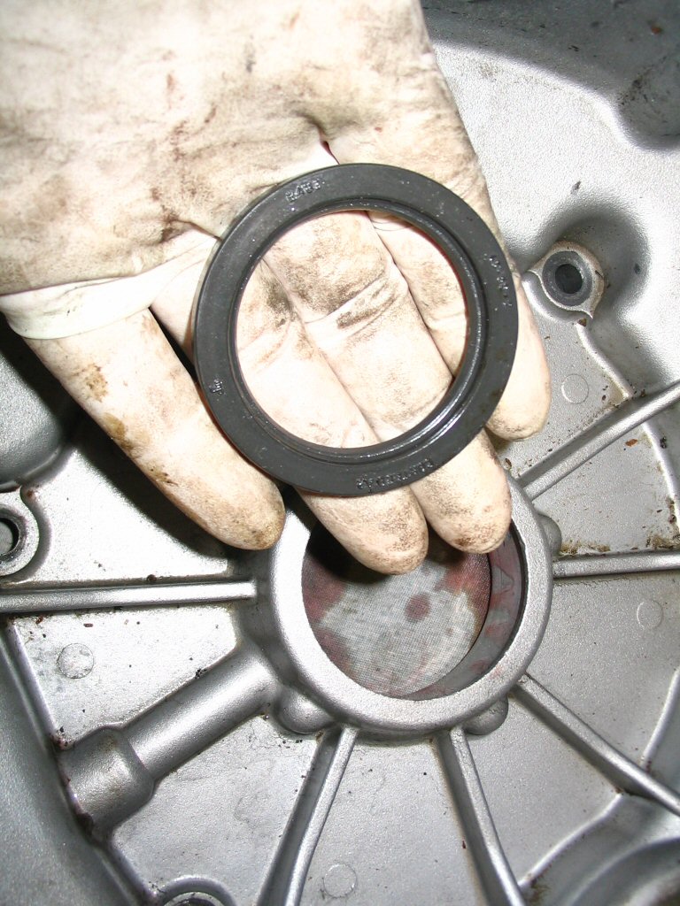
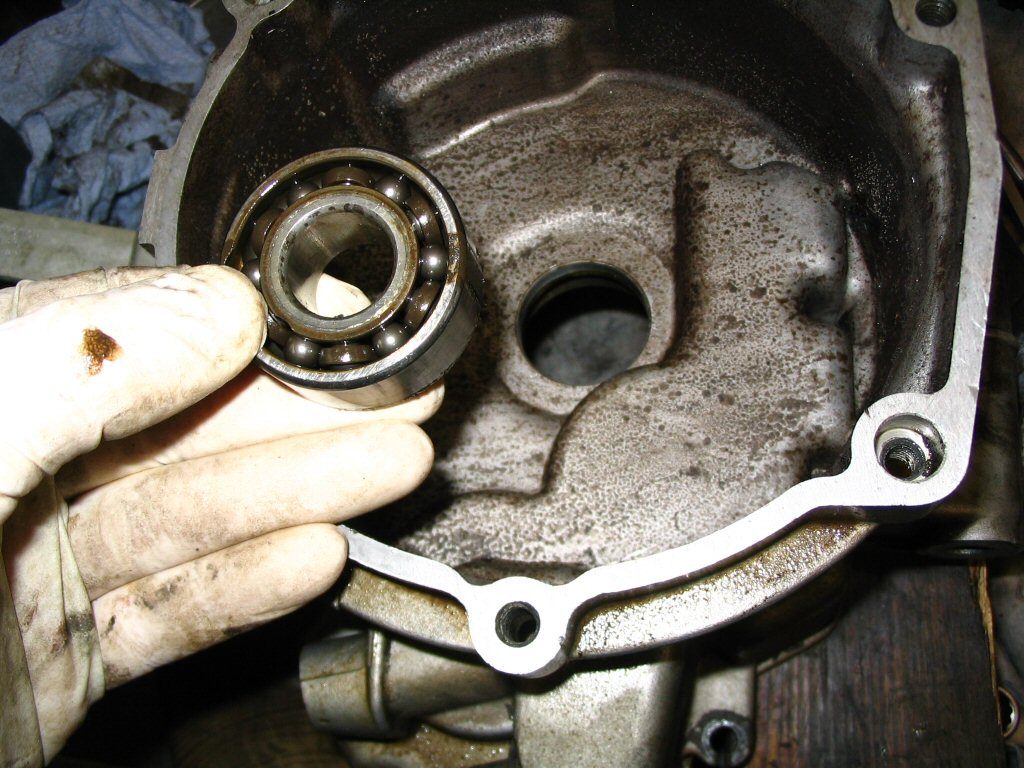
Here is the removed seal. The lip of the seal presses against the clutch basket.
Photo courtesy of Gregory Bender.
Press out the front bearing for the input shaft.
Photo courtesy of Gregory Bender.
Here is the blind hole bearing puller I used to remove the bearings from the case.
Photo courtesy of Gregory Bender.
Another view of the blind hole bearing puller.
Photo courtesy of Gregory Bender.
Another view of the blind hole bearing puller.
Photo courtesy of Gregory Bender.
Another view of the blind hole bearing puller.
Photo courtesy of Gregory Bender.
Another view of the blind hole bearing puller.
Photo courtesy of Gregory Bender.
Another view of the blind hole bearing puller.
Photo courtesy of Gregory Bender.
Another view of the blind hole bearing puller.
Photo courtesy of Gregory Bender.
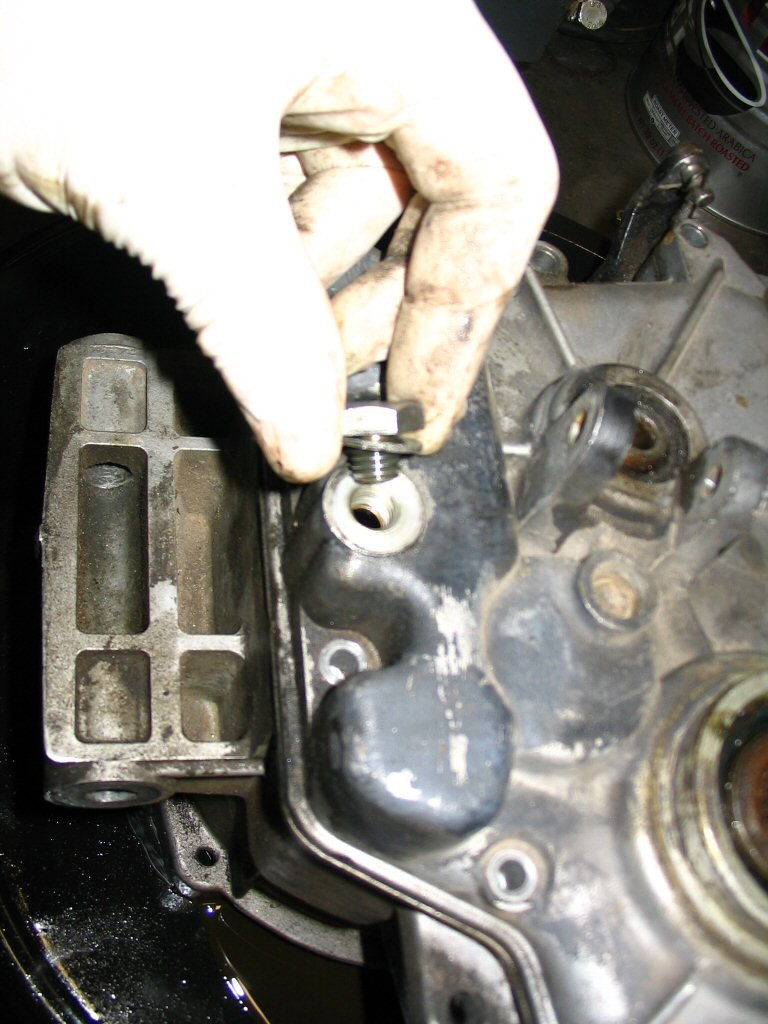
Removing the bolt from the case. I think the purpose of this bolt was to prevent the shift shaft from rotating too far. I can't recall for sure now, though.
Photo courtesy of Gregory Bender.
Here is the bolt removed.
Photo courtesy of Gregory Bender.
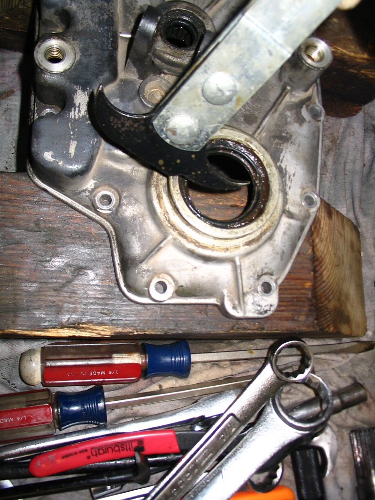
Use a seal puller to remove the output shaft (layshaft) seal from the rear cover.
Photo courtesy of Gregory Bender.
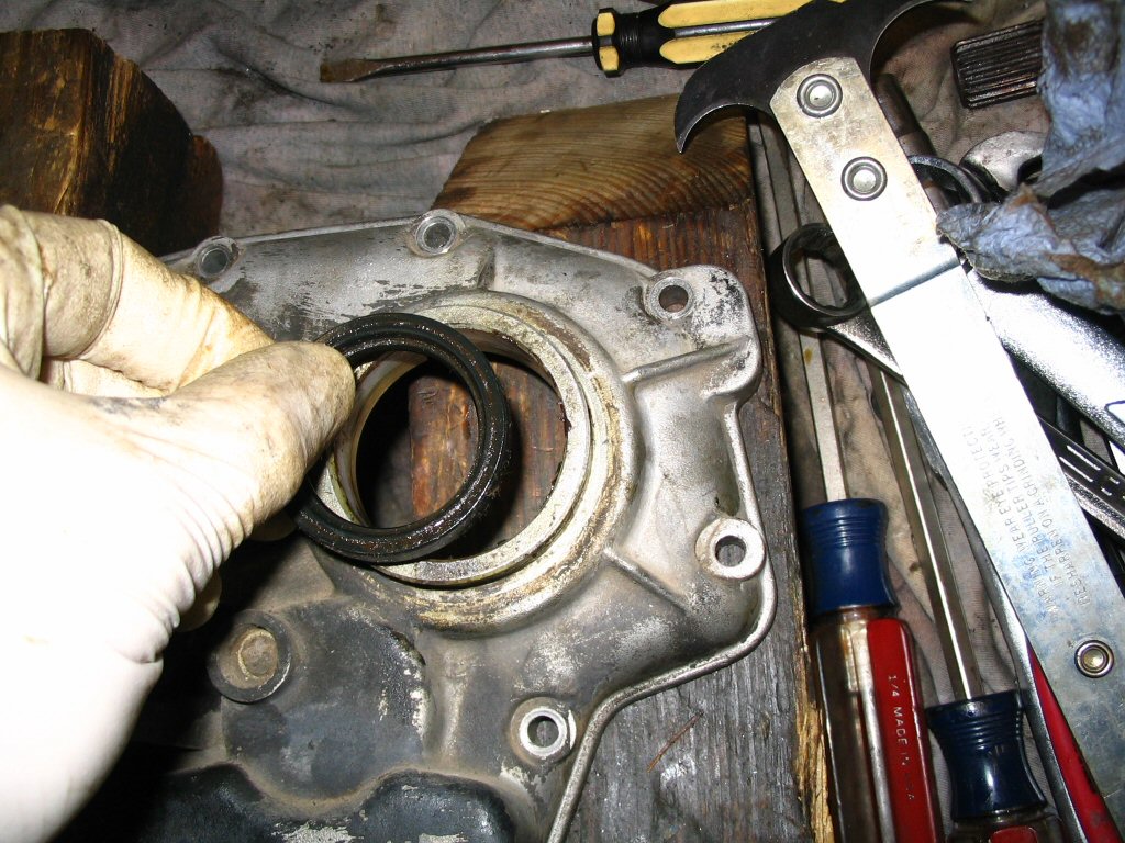
Here is the removed seal.
Photo courtesy of Gregory Bender.
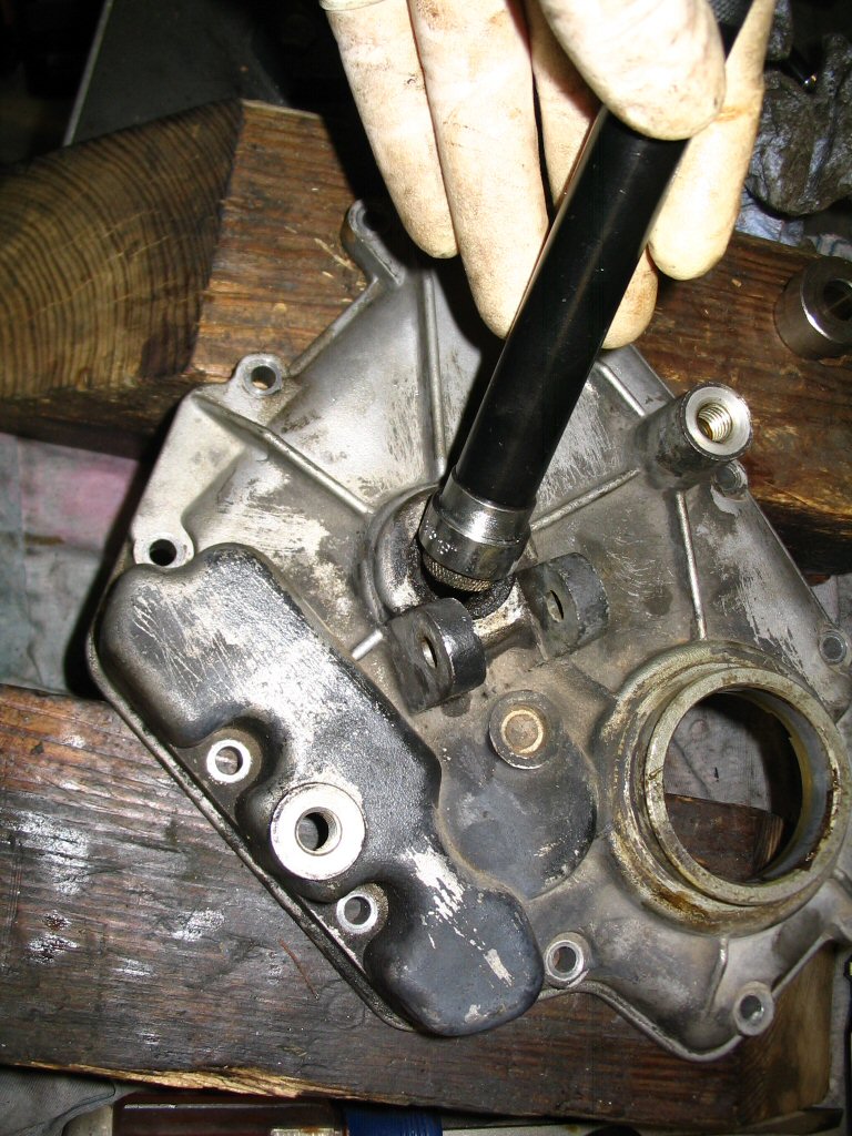
Use a small driver to drive out the seal from the rear cover. The bearing will come with it. Take care so as to not destroy the bearing (I do not use a blind hole bearing puller on these bearings unless I have to). Use the largest size driver you can fit.
Photo courtesy of Gregory Bender.
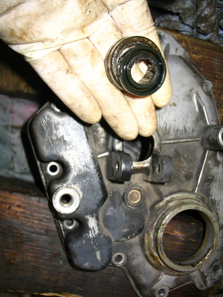
Here is the seal and bearing removed.
Photo courtesy of Gregory Bender.
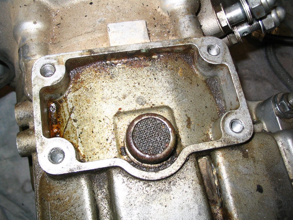
Here is the vent. I never did remove this from the case. Just cleaned it thoroughly in place along with the rest of the case.