2013 March 19: Install the left cylinder head
Created:
Updated:
First entry|Previous entry|Next entry|Last entry
// //
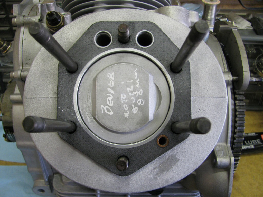 Continuing with the left side, here is the head gasket in place. Note oil return hole is properly aligned.
Photo courtesy of Gregory Bender.
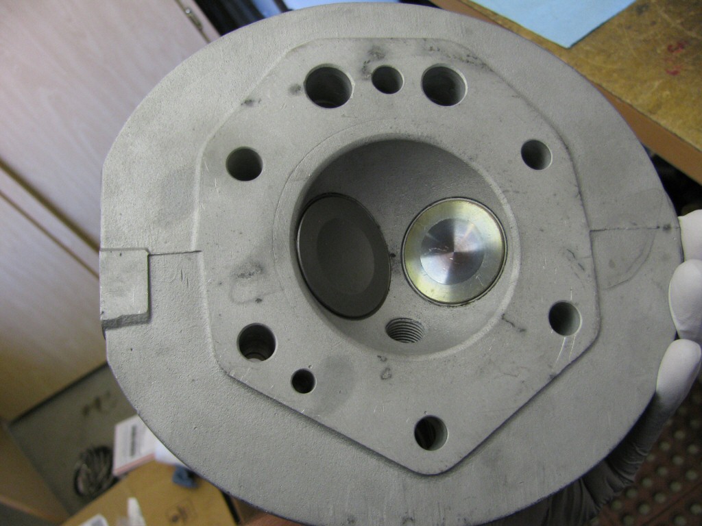 The reconditioned cylinder head: new exhaust valve, re-used intake valve, new valve guides.
Photo courtesy of Gregory Bender.
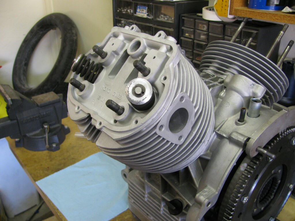 Cylinder head in place.
Photo courtesy of Gregory Bender.
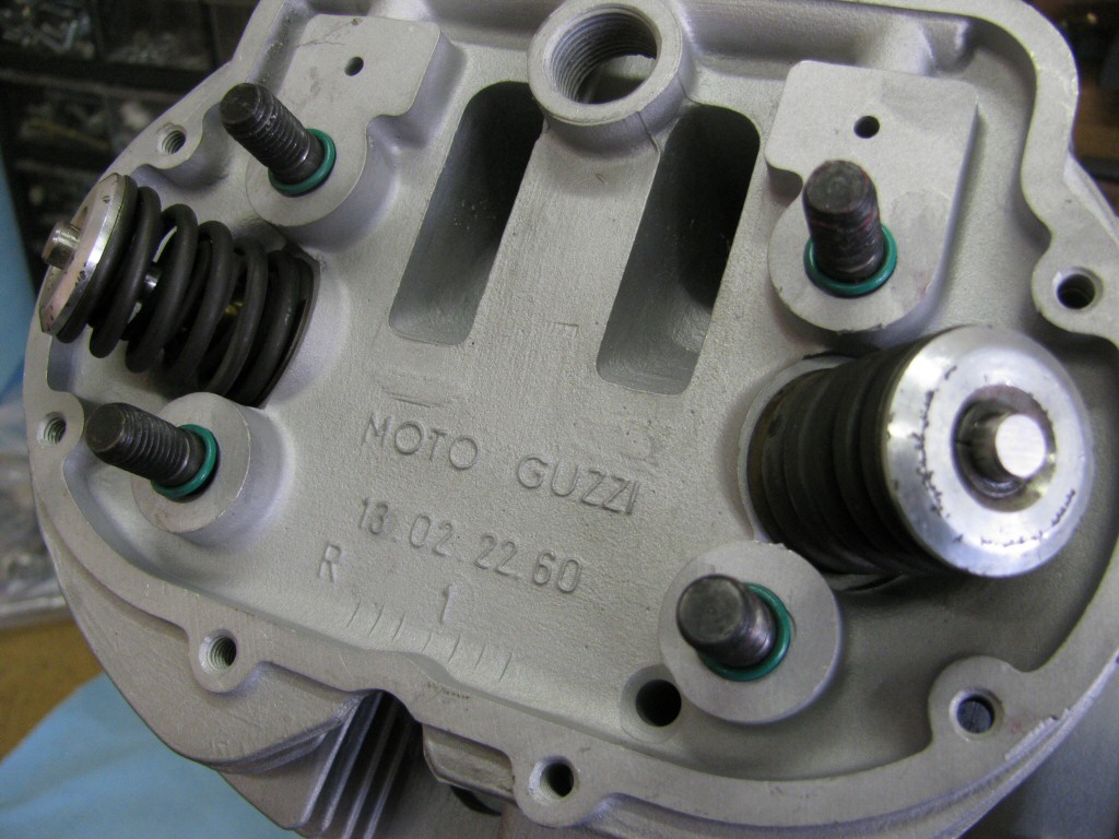 O-rings fit to the four protruding studs.
Photo courtesy of Gregory Bender.
 Rocker arm tressle fit.
Photo courtesy of Gregory Bender.
 Flat washers fit above the tressle.
Photo courtesy of Gregory Bender.
 Flat washer fit to the
 6 o'clock
stud.Photo courtesy of Gregory Bender.
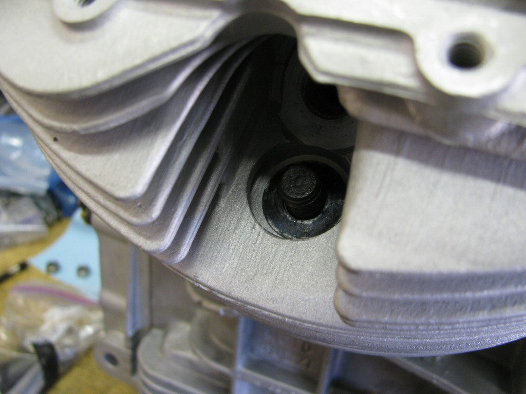
 You can't see it, but a flat washer is fit to the
 12 o'clock
stud.Photo courtesy of Gregory Bender.
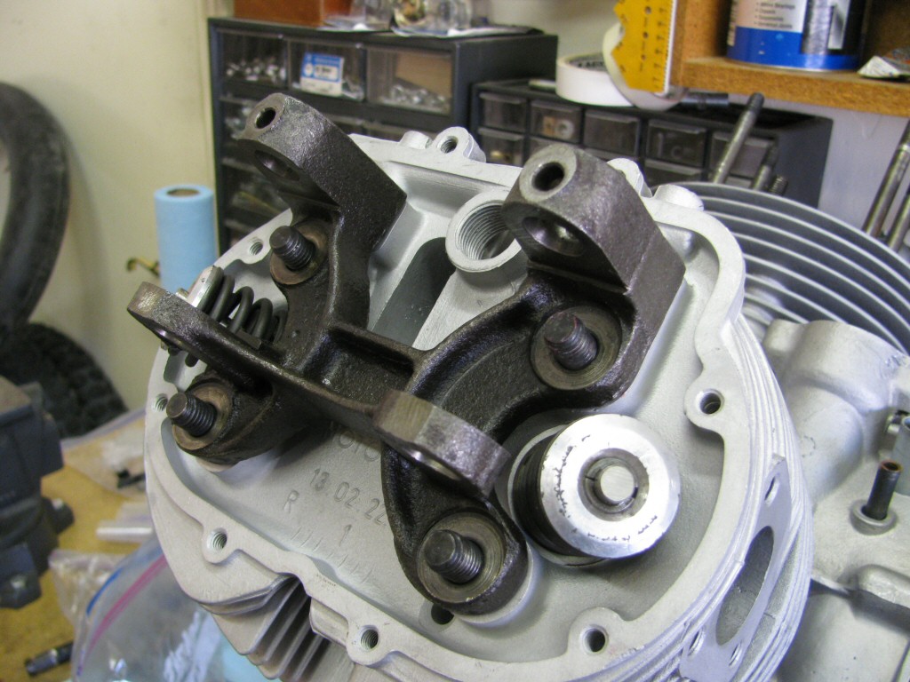
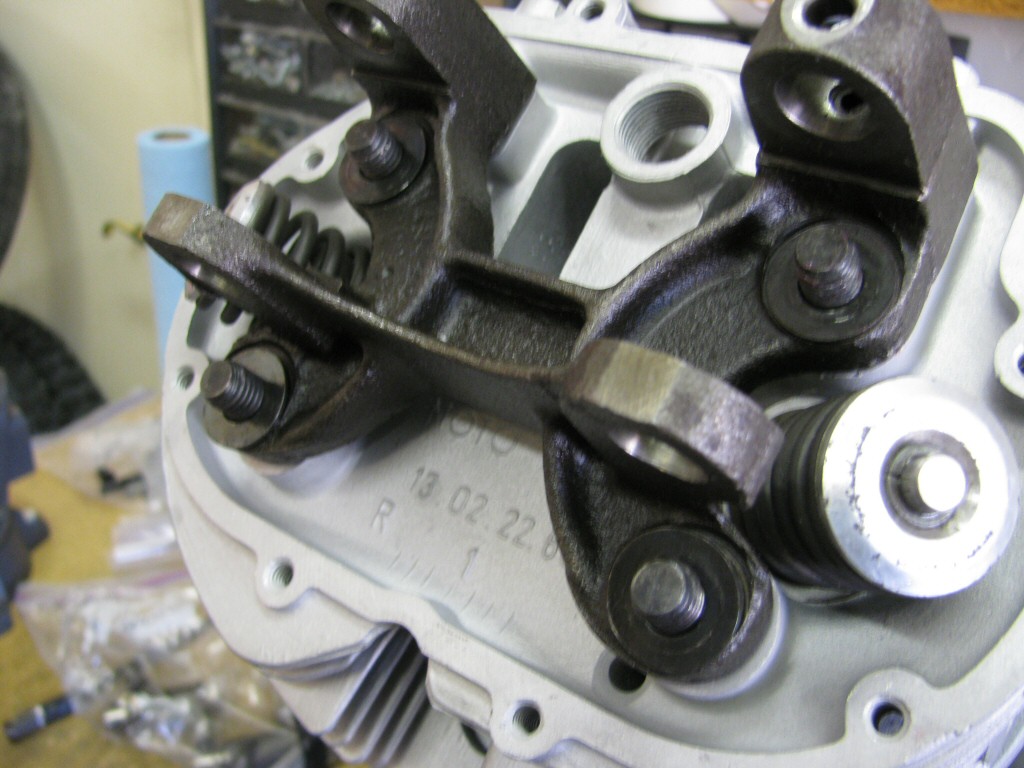
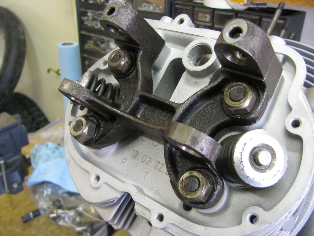 Four nuts on the tressle studs.
Photo courtesy of Gregory Bender.
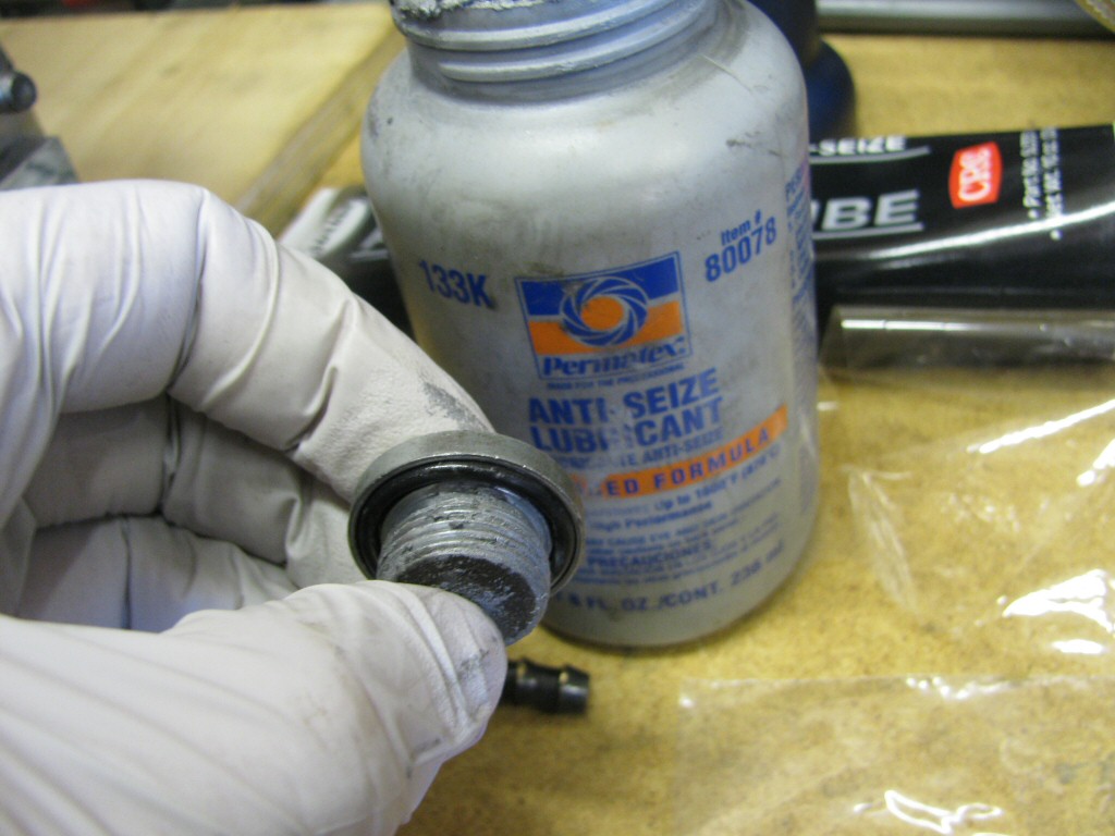
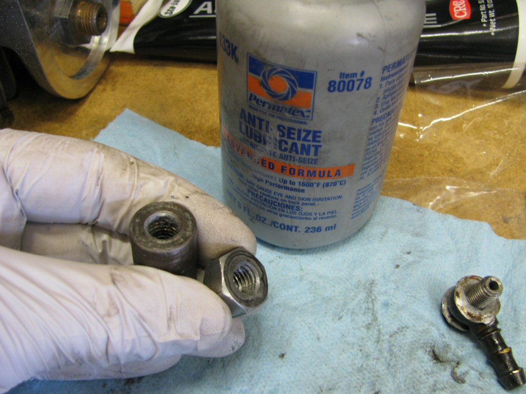 Because they are exposed to the elements, I apply antiseize to the threads of the
 12 o'clock
and 6 o'clock
nuts.Photo courtesy of Gregory Bender.
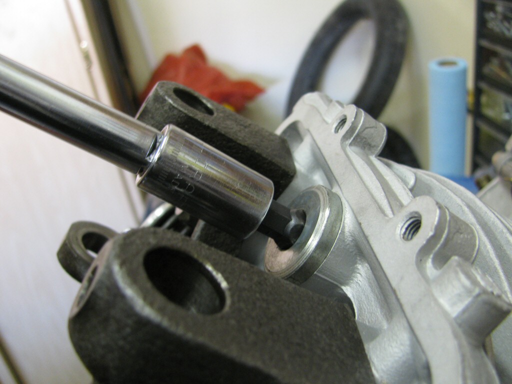
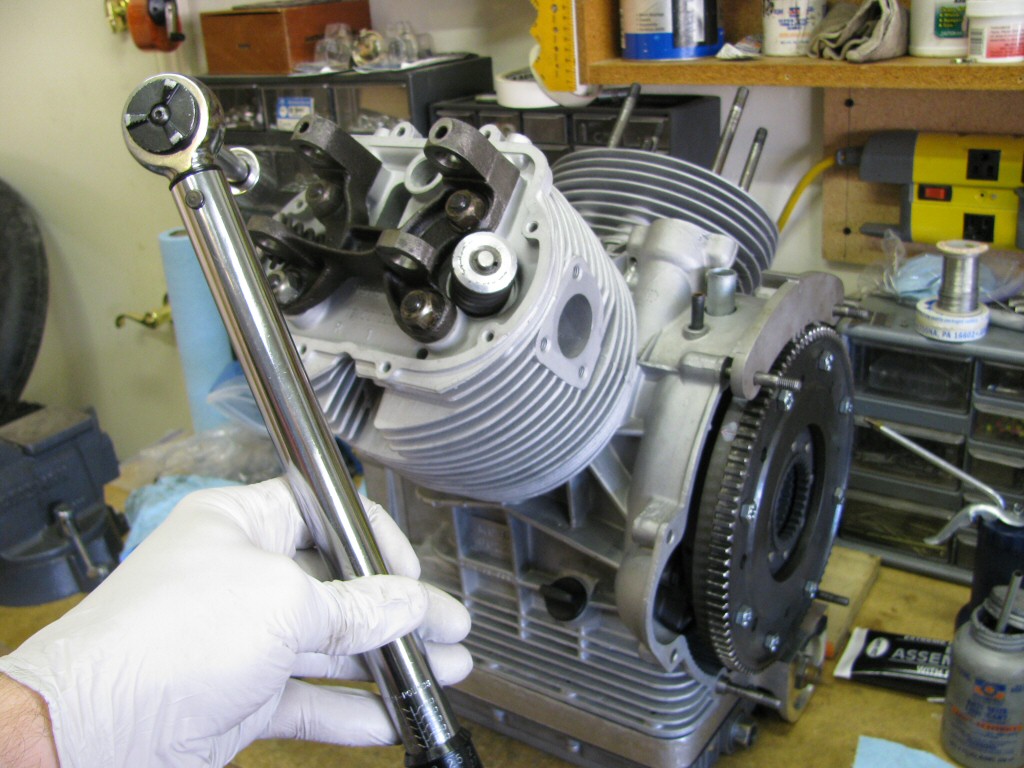 Then the nuts get torqued to spec.
Photo courtesy of Gregory Bender.
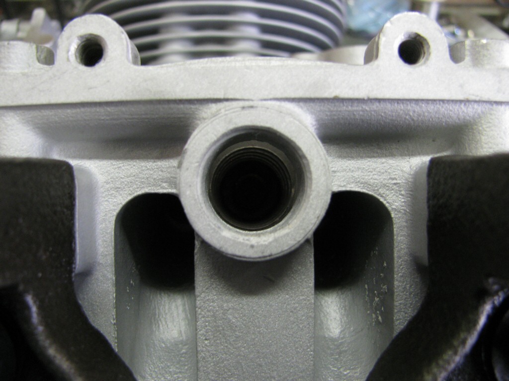
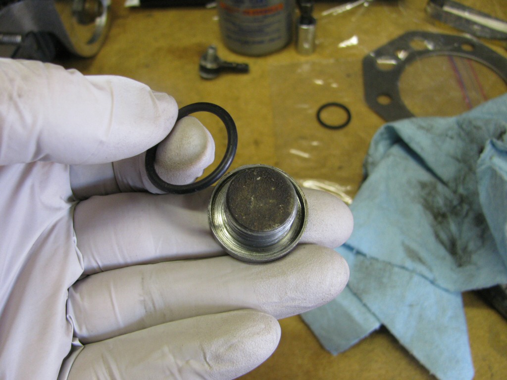 I fit a new O-ring to the plug for the
 12 o'clock
nut access hole.Photo courtesy of Gregory Bender.
 Again, I apply anti-seize to the threads.
Photo courtesy of Gregory Bender.
 The plug tightened in place.
Photo courtesy of Gregory Bender.
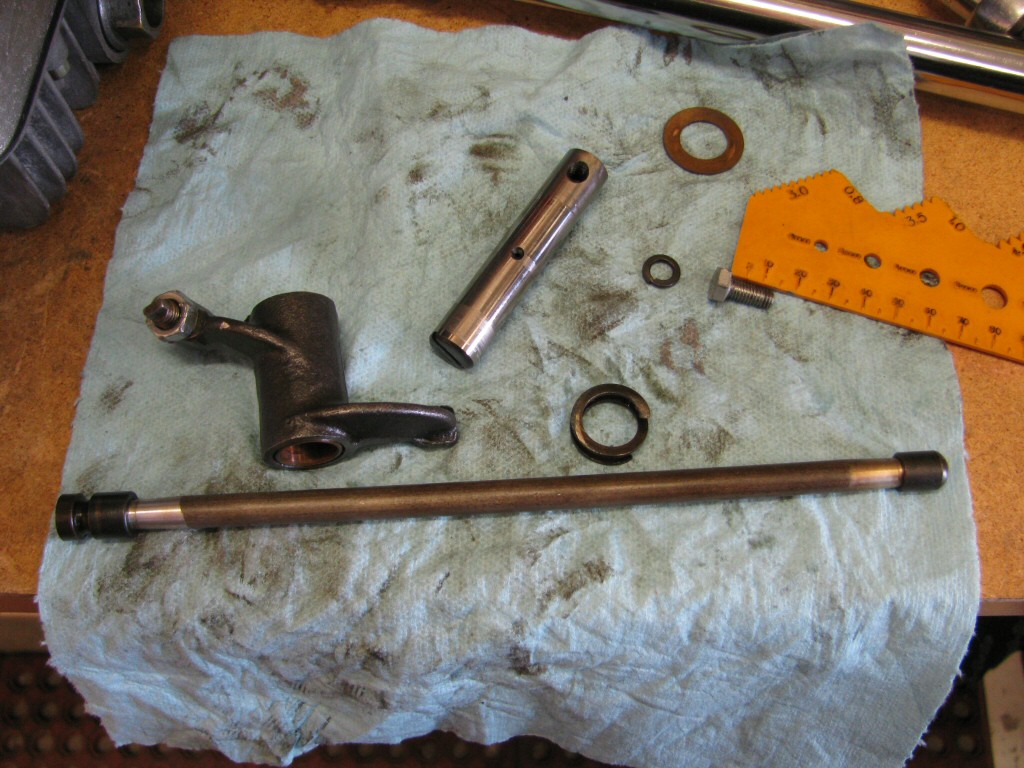 Here are the parts needed to actuate the intake valve.
Photo courtesy of Gregory Bender.
 Everything gets a good coating of assembly lube.
Photo courtesy of Gregory Bender.
 The intake valve components in place.
Photo courtesy of Gregory Bender.
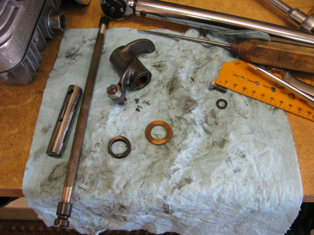 Here are the parts needed to actuate the exhaust valve.
Photo courtesy of Gregory Bender.
 Everything gets a good coating of assembly lube.
Photo courtesy of Gregory Bender.
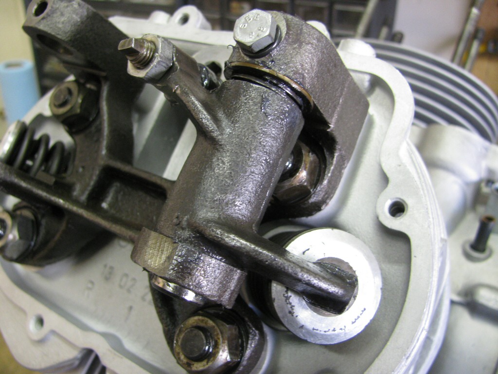
 The exhaust valve components in place, ready to torque the bolts that secure the rocker arm in place.
Photo courtesy of Gregory Bender.
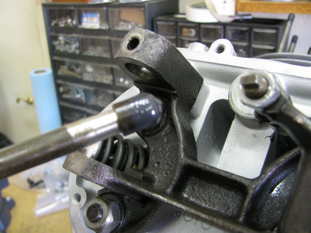
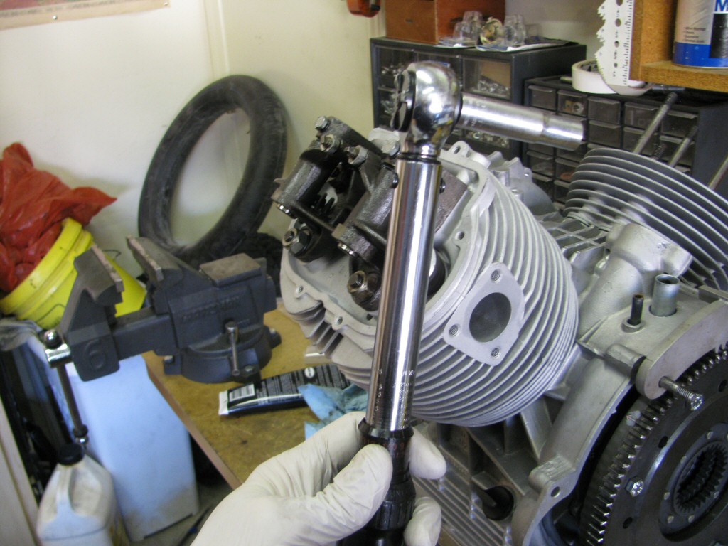
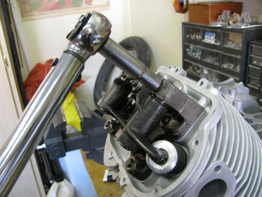 Torqueing the bolts that secure the rocker arm in place.
Photo courtesy of Gregory Bender.
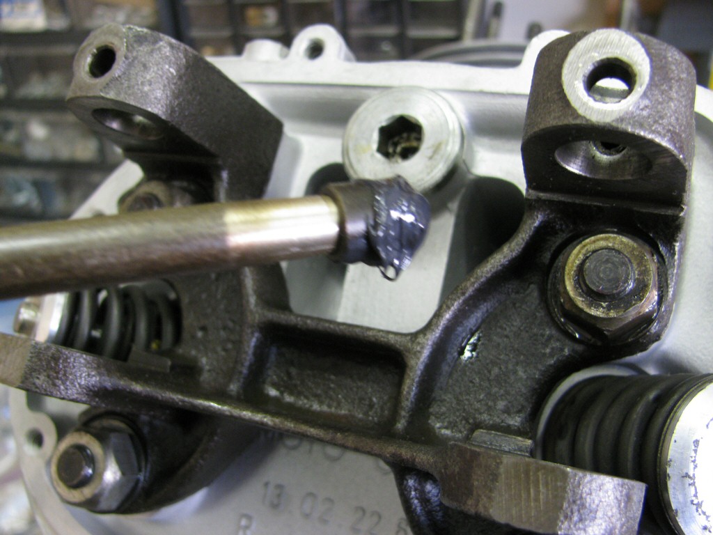
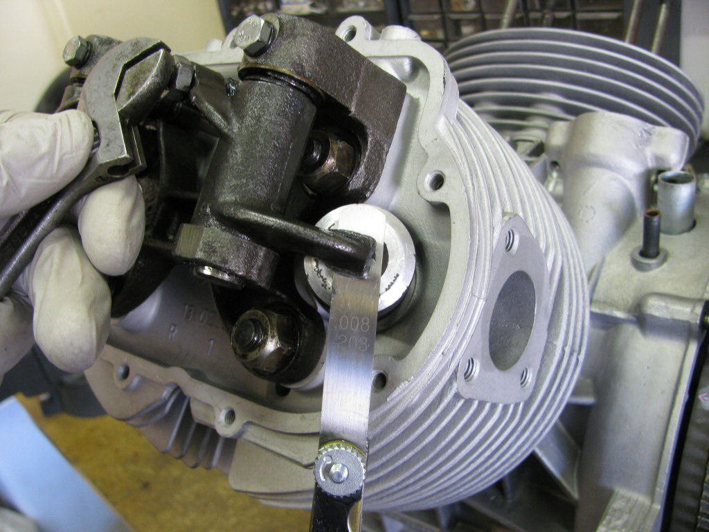 I set the valve clearances per Moto Guzzi specifications.
Photo courtesy of Gregory Bender.
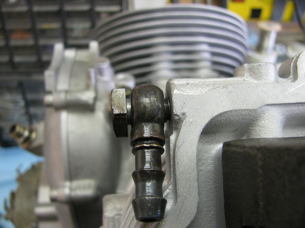 Banjo bolt for the oil feed line loosely fit.
Photo courtesy of Gregory Bender.
First entry|Previous entry|Next entry|Last entry