Moto Guzzi V700, V7 Special, Ambassador, 850 GT, 850 GT California, Eldorado, and 850 California Police models
Created:
Updated:
I am not a proponent of relocating the fuse block and/or distribution panel outside of the headlight bucket. Here are some replacement fuse boxes and alternative fuse solutions that others have tried.
Josh works at Moto Guzzi Classics and created/engineered this replacement fuse block, himself. This is - by far - the best replacement fuse block I have seen for the Loopframes. It is well made, ready-to-install, and definitely up to the task. We've waited for something good to be available for years. Here it is.
Feel free to contact MG Cycle or call Josh directly at 562-986-0070 with any questions.
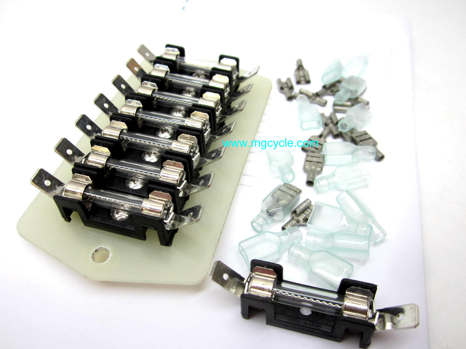
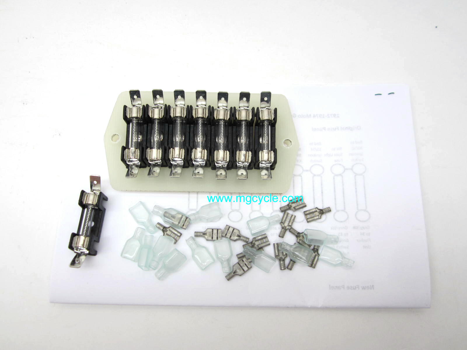
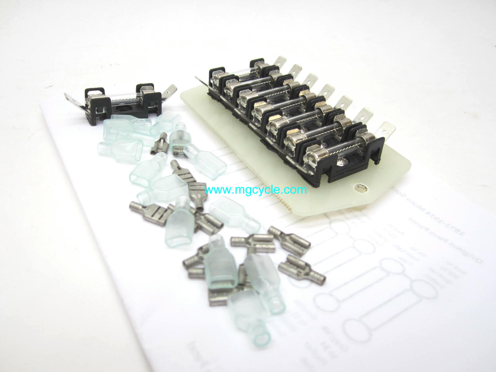
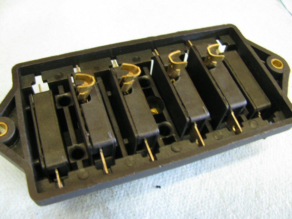
Replacement fuse block for Moto Guzzi V700, V7 Special, Ambassador, 850 GT, 850 GT California, Eldorado, and 850 California Police models.
If you are looking for a fuse panel that can be secured in the existing location, find one that has mounting holes that are spaced at 105 mm (~4 1⁄8 inch).
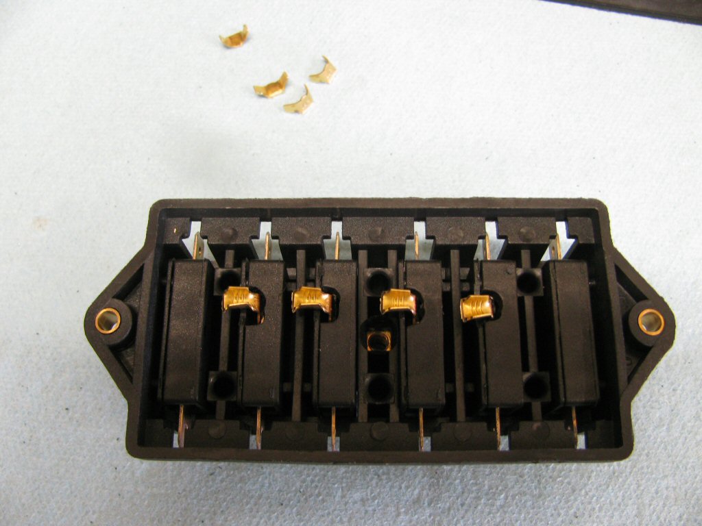
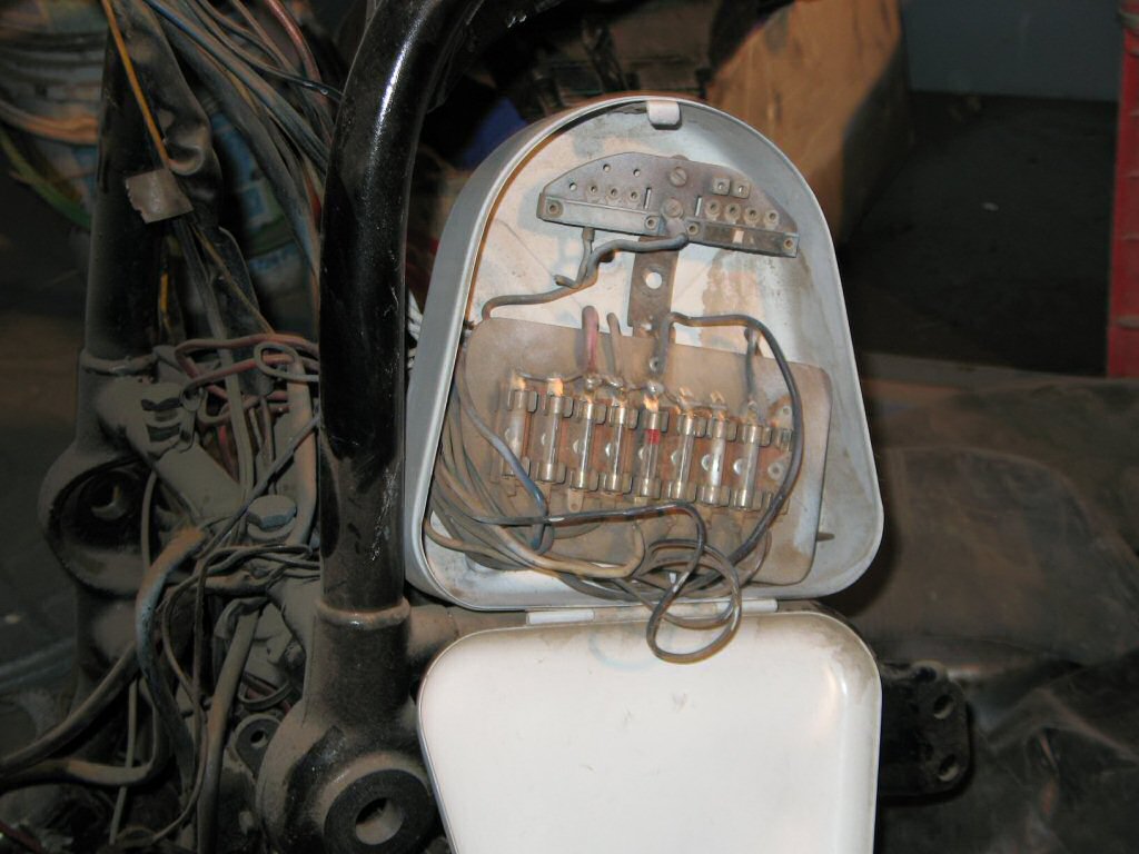
I found one that bolts perfectly in the stock location inside the headlight and takes ATO/ATC blade style fuses. I purchased it from Waytek. Search for item number 46081. My original fuse block is holding up very well, but I have used this replacement on customer's machines with very good success. A few notes:
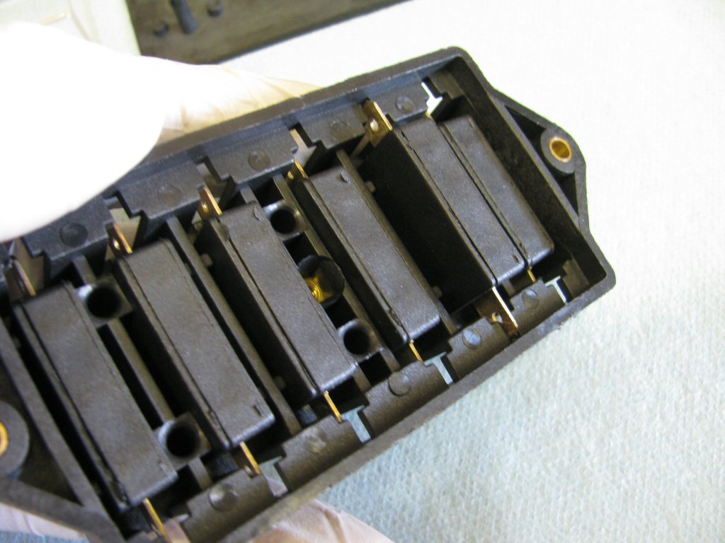
The six fuse slots it has are adequate for both civilian and police models.
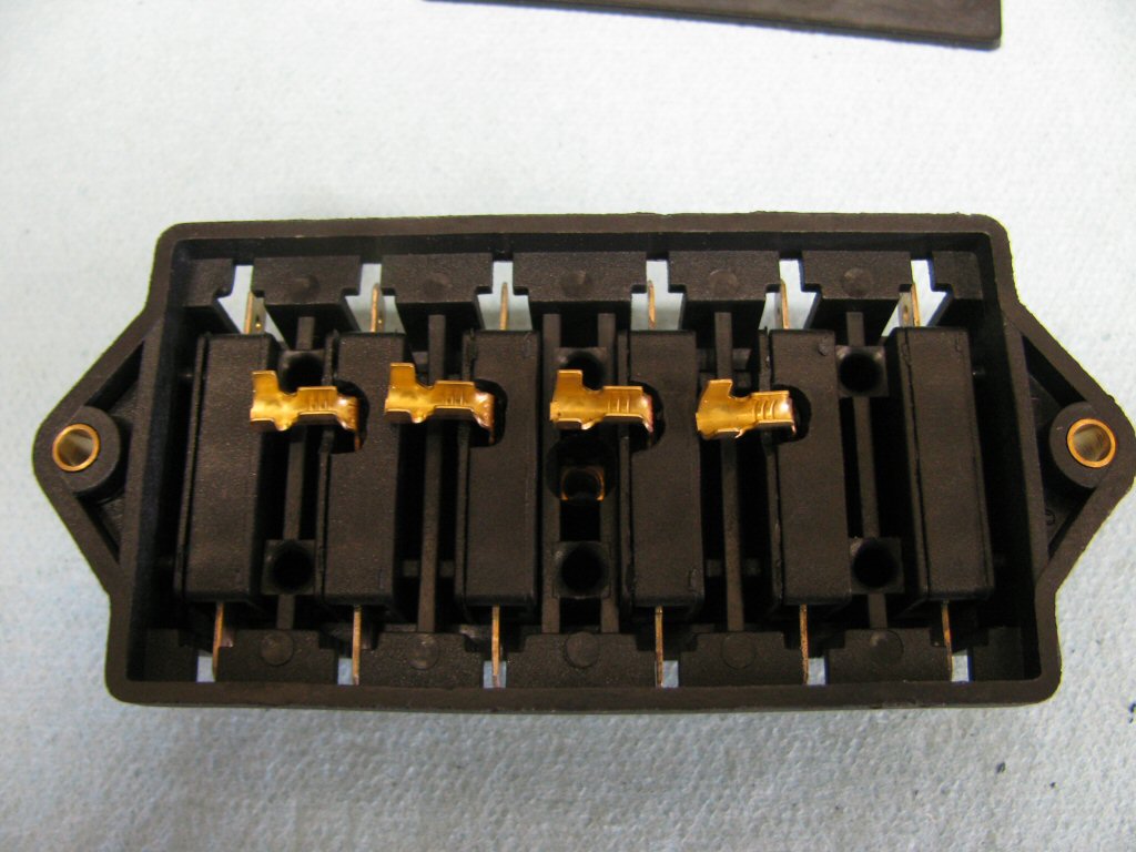
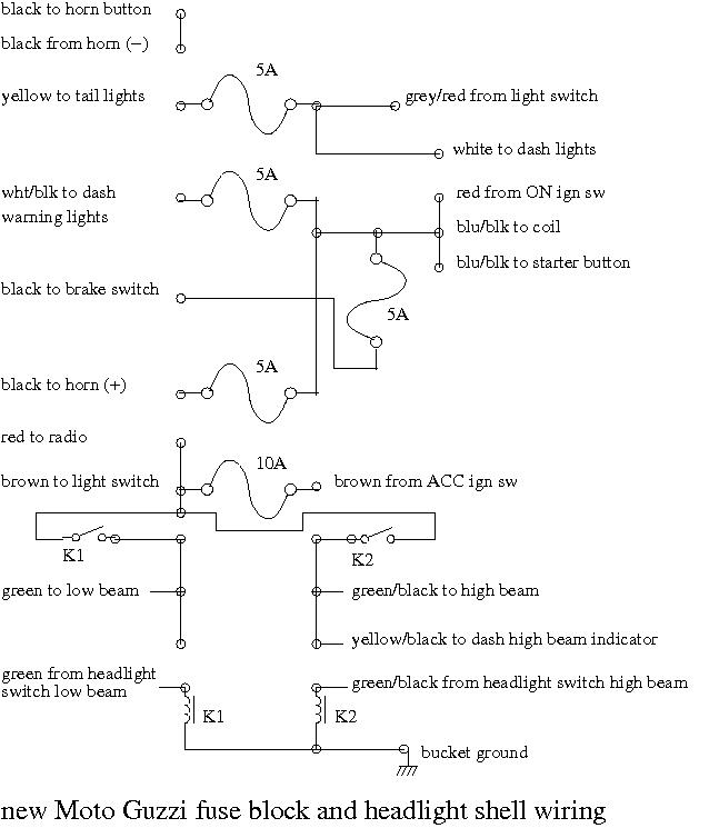
The original fuse panel has linked some of the circuits on the top row (refer to the wiring diagram for details). Of course, this replacement panel does not come with any joined circuits. You will need to want to modify the fuse block as described below.
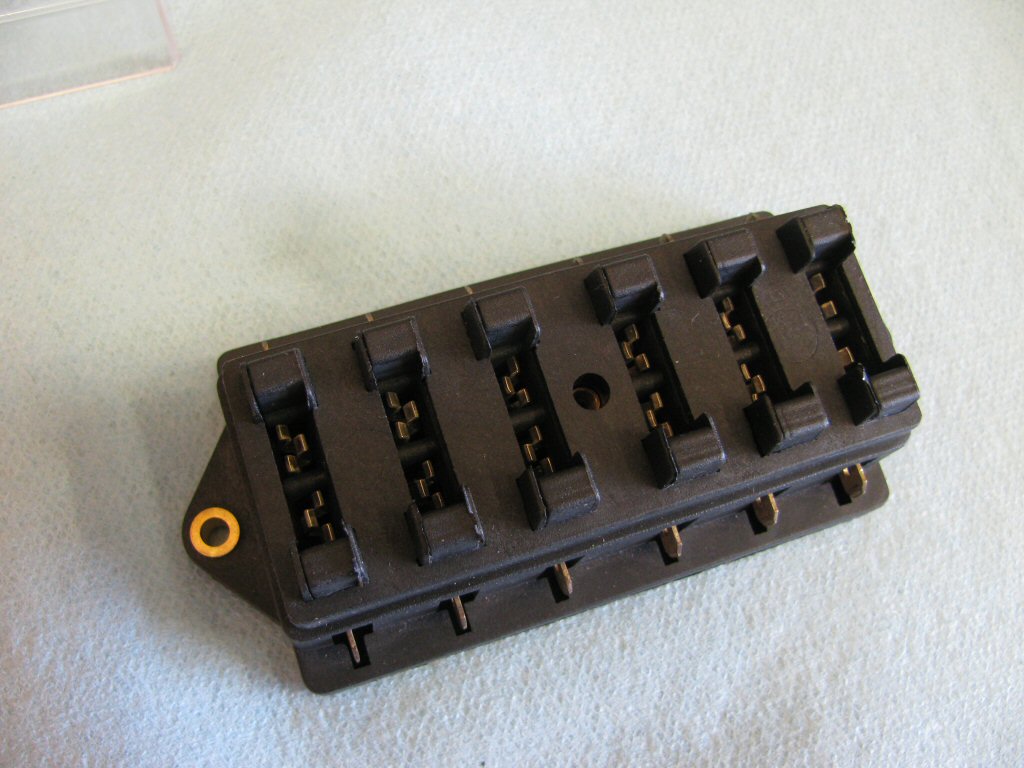
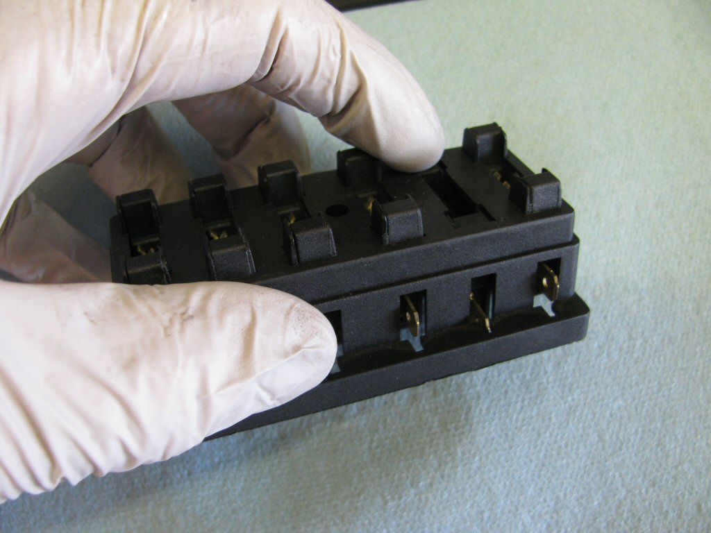
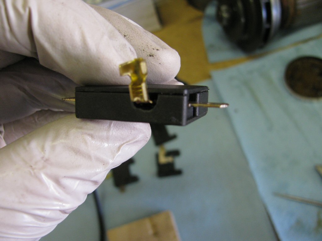
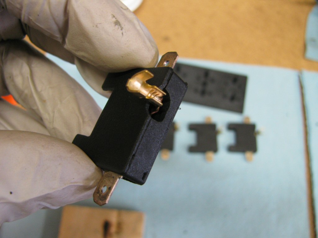
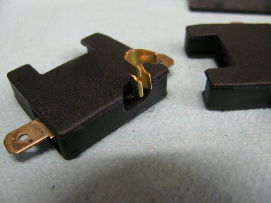
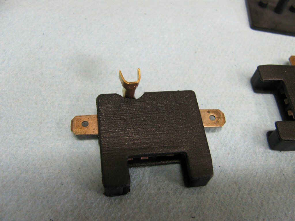
The original fuse panel accepts 4 mm bullet terminals. This replacement accepts simple 1⁄4 inch spade terminals. You will need to replace the bullet terminals with spade terminals.
Use 15 amp fuses as the fuse block is rated for 15 amp fuses. This is plenty heavy enough for our circuits, even though Moto Guzzi originally used 25 amp fuses.
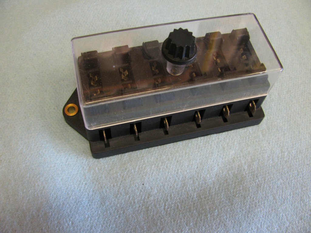
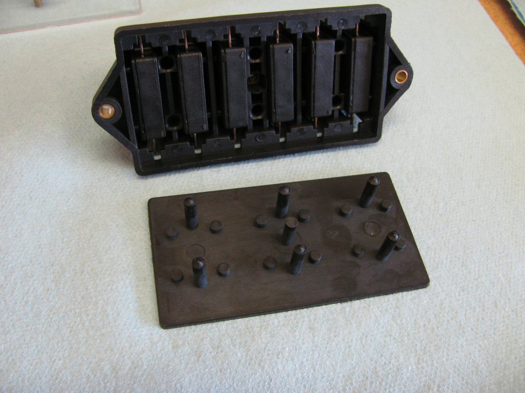
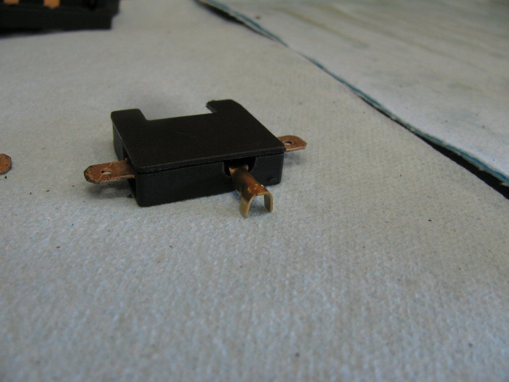
While it comes with a clear plastic cover and a knob to secure the clear plastic cover in place, neither are needed and will interfere with the headlight (except on the early, deeper headlight buckets). Simply discard them.
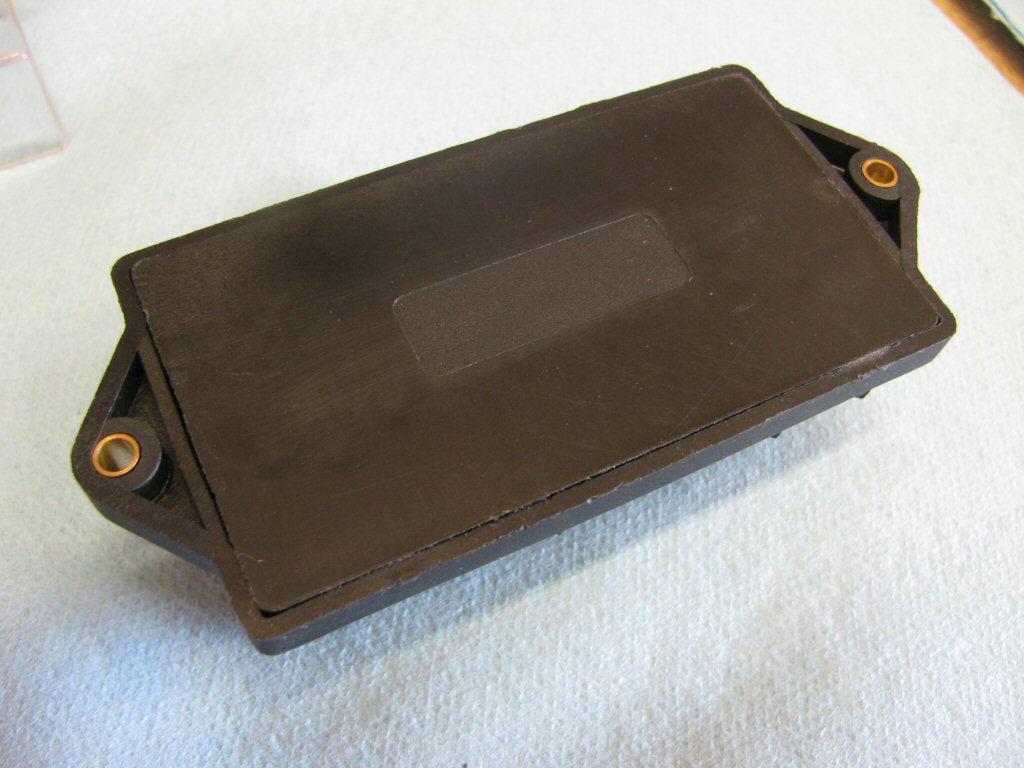
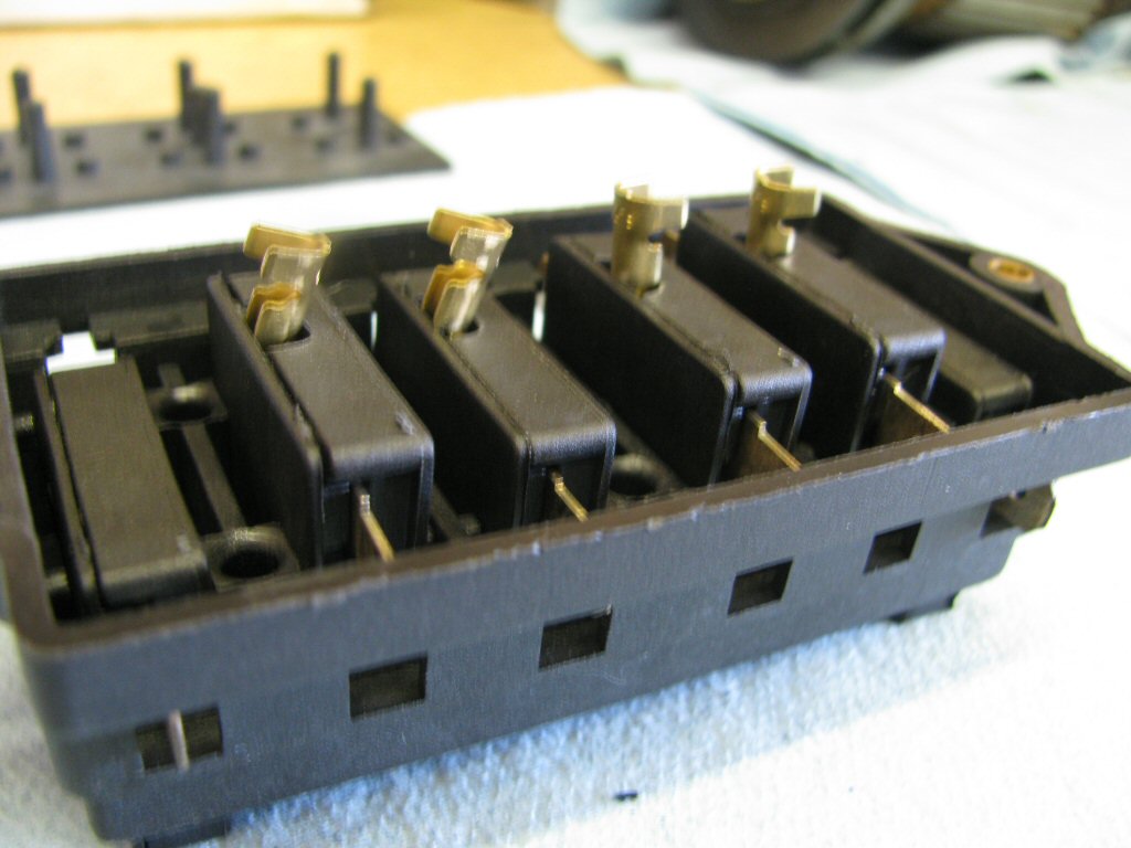
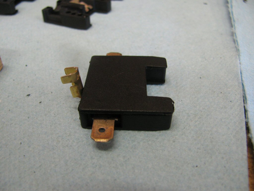
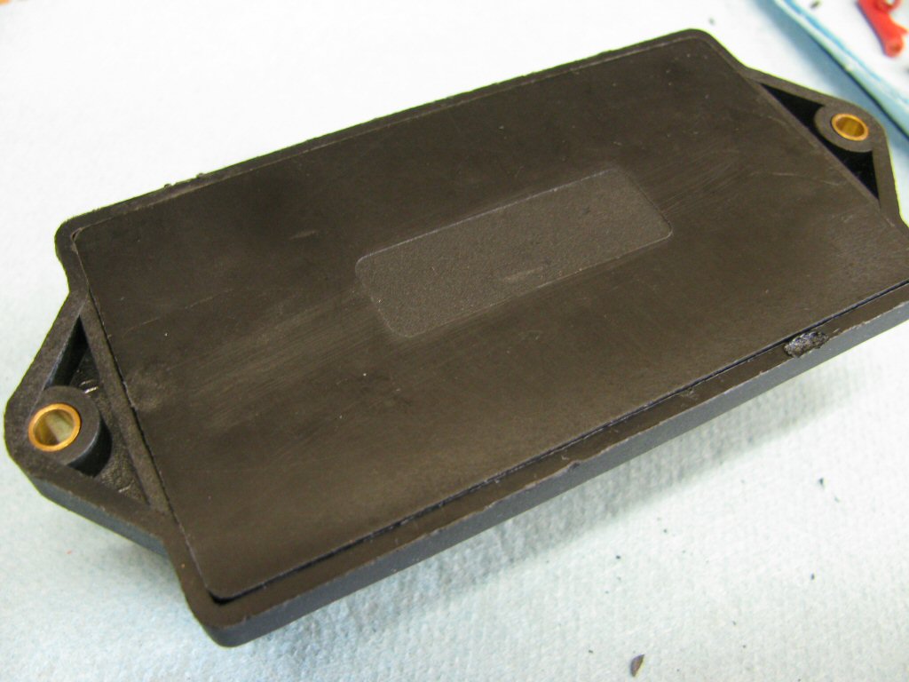
Waytek item number 46081. A perfect fit to replace the original fuse panel in Moto Guzzi V700, V7 Special, Ambassador, 850 GT, 850 GT California, Eldorado, and 850 California Police motorcycles.
Waytek item number 46081. A perfect fit to replace the original fuse panel in Moto Guzzi V700, V7 Special, Ambassador, 850 GT, 850 GT California, Eldorado, and 850 California Police motorcycles.
Please note: Fitment of this fuse block is not perfect. Specifically, it is too tall for some headlight bucket/headlight combinations. That is, there is the chance that the rear of the headlight plug will interfere with the fuses and prevent complete assembly of the headlight bucket. This is almost never a problem with the longer headlight bucket that was fit to V700 models. However, it is a real concern for some - but not all - of the shorter headlight buckets typically fit to all Ambassador and Eldorado models.
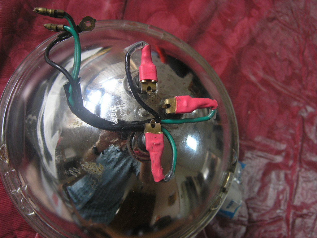
A solution to this problem is to not use a headlight plug at all. Instead, bend the contacts on the headlight bulb and then fit individual terminals. This solution is not ideal, but it does get the job done.
Bent contacts on a headlight bulb to afford fitment inside the headlight bucket.
Photo courtesy of John Leek.
Bent contacts on a headlight bulb to afford fitment inside the headlight bucket.
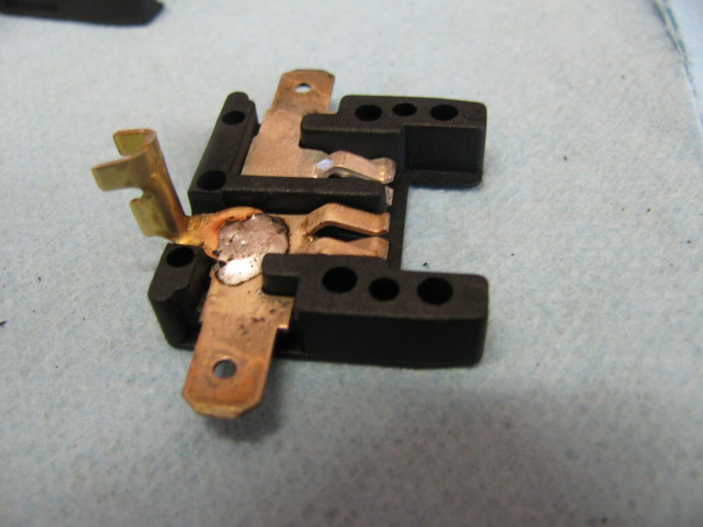
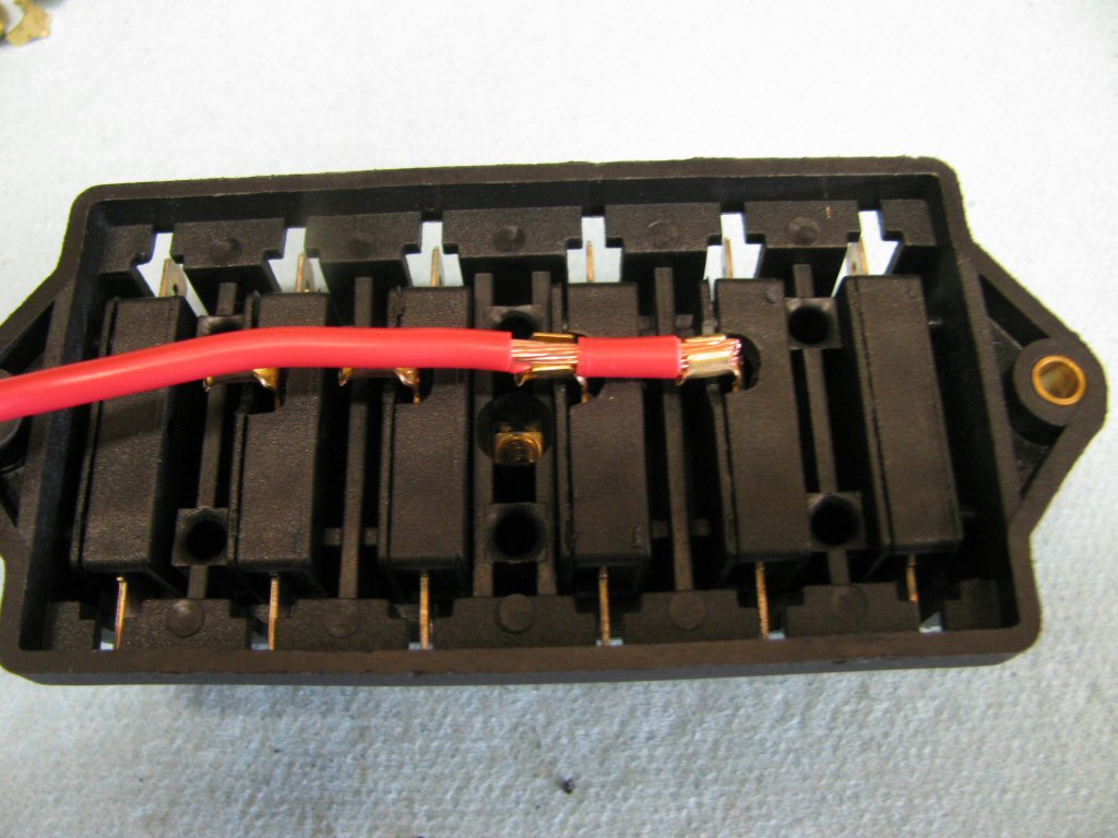
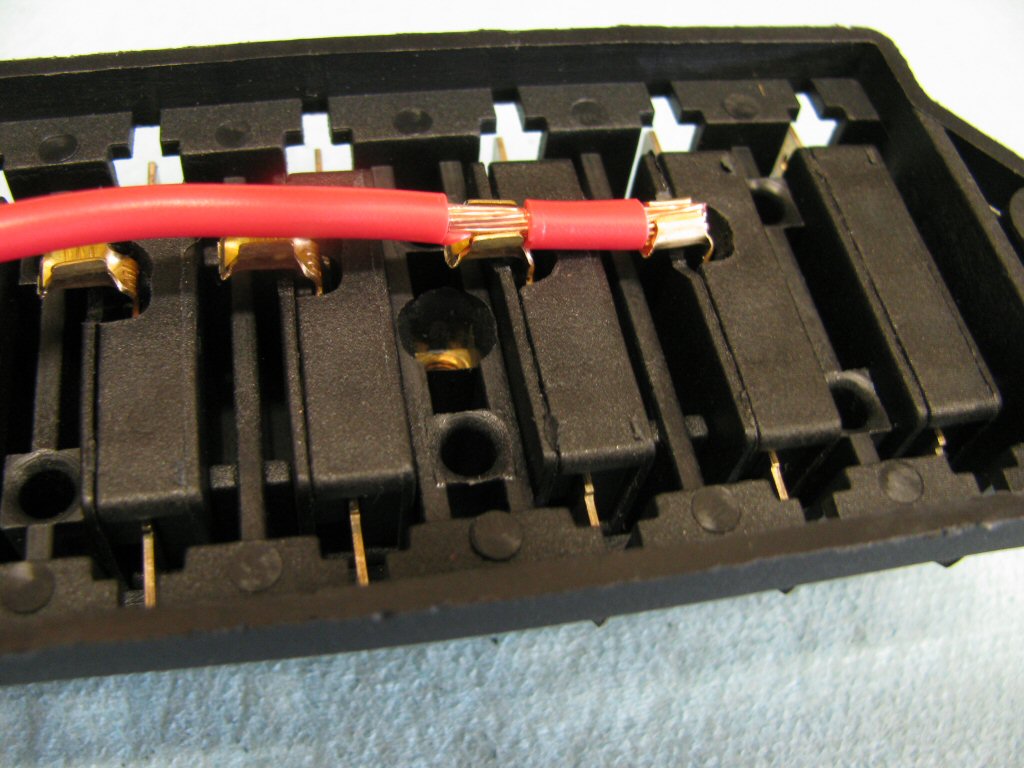
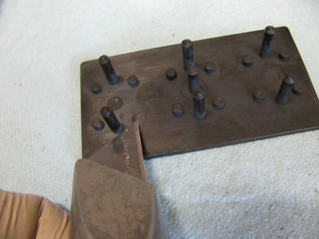
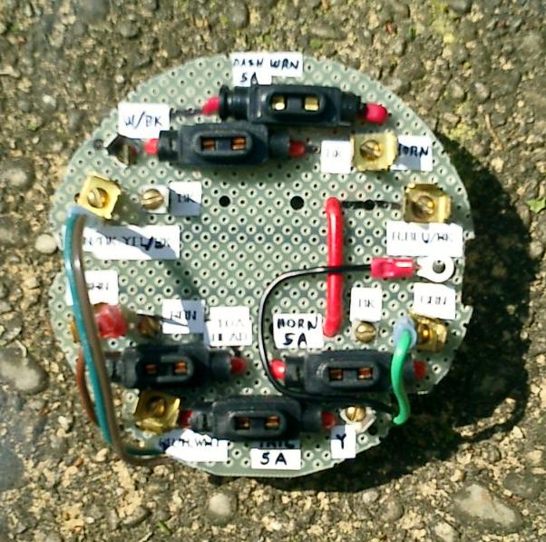
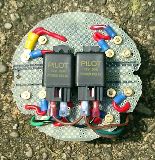
I installed this fuse block once without making the following described modification. Without the linked top terminals - as is on the original fuse block - the jumper wires become quite complex and cumbersome. Hence my decision to link the top terminals.
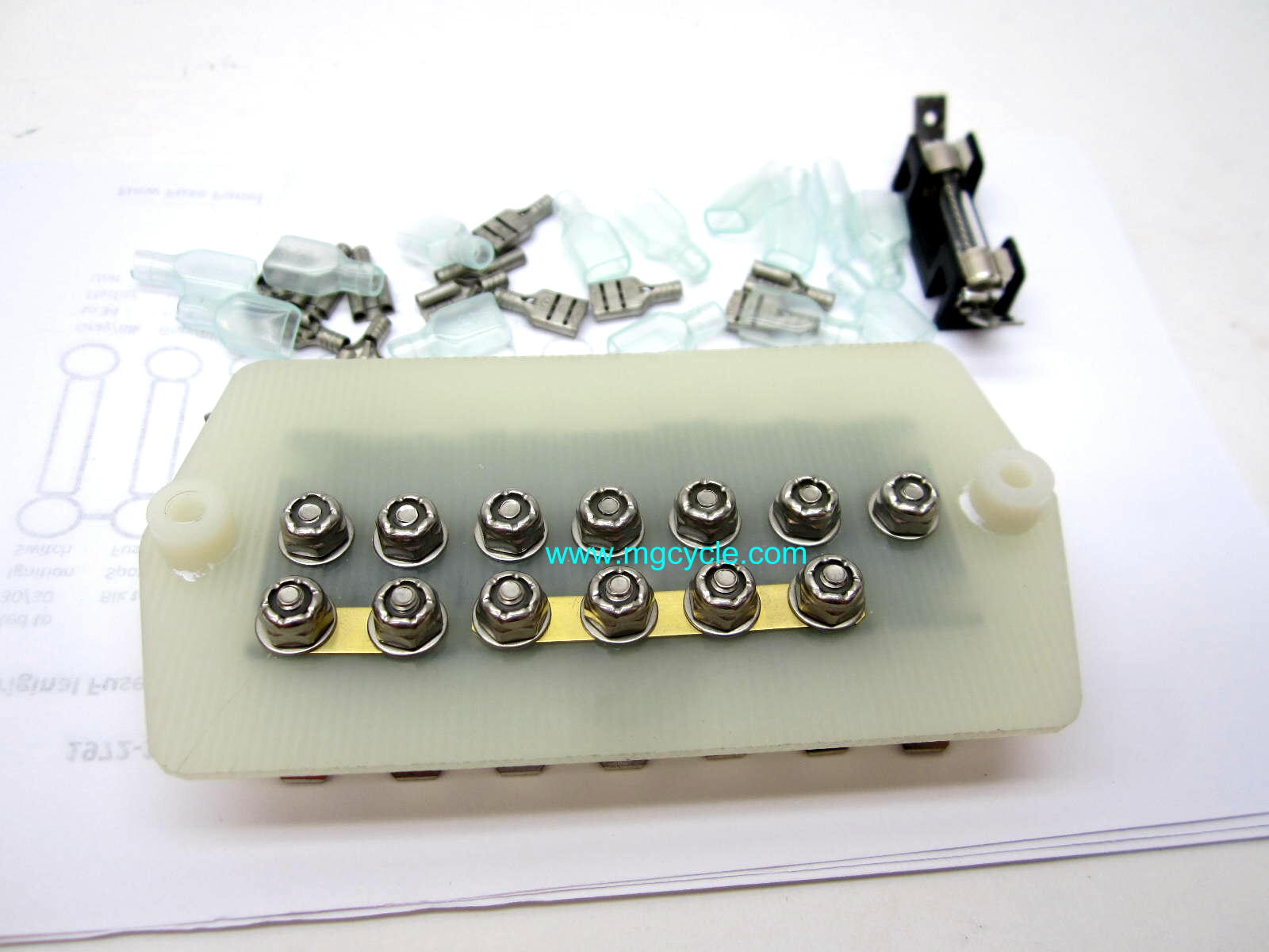
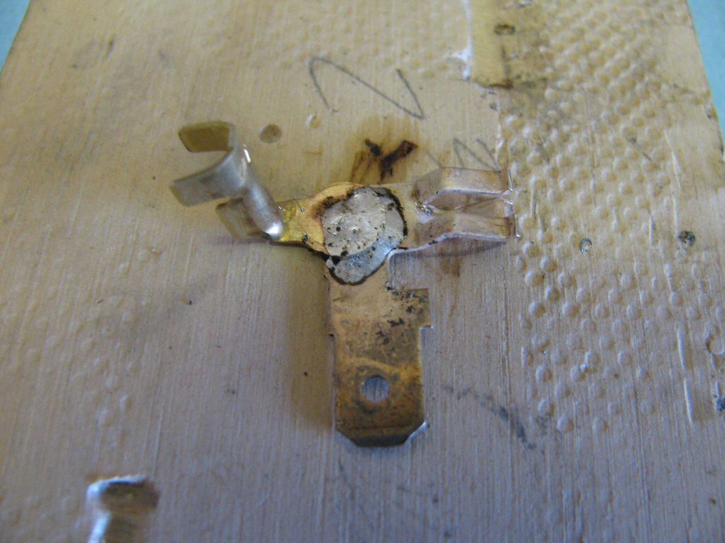
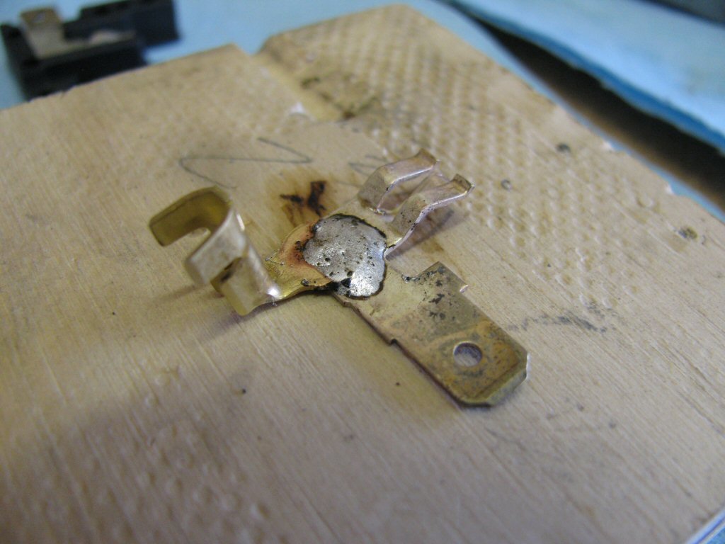
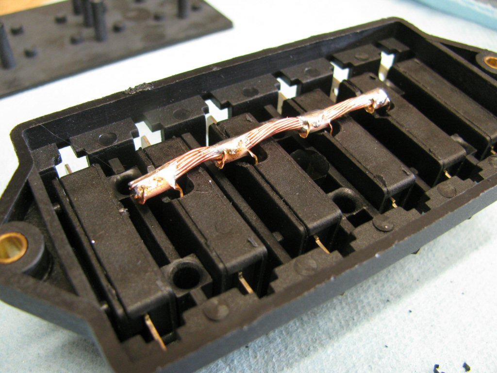
I chose to use 3 mm heavy duty ring terminals with a single length of 12 AWG wire joining the terminals. I had initially thought about simply soldering the 12 AWG wire directly to the fuse terminals (without the use of ring terminals). However, 12 AWG wire does not easily bend to conform to the tight fit within the fuse box. Therefore, I decided to use the 3 mm ring terminals. I'm very glad I chose to use these ring terminals and they are working out very well. By the way, 4 mm heavy duty ring terminals are too large for this application.
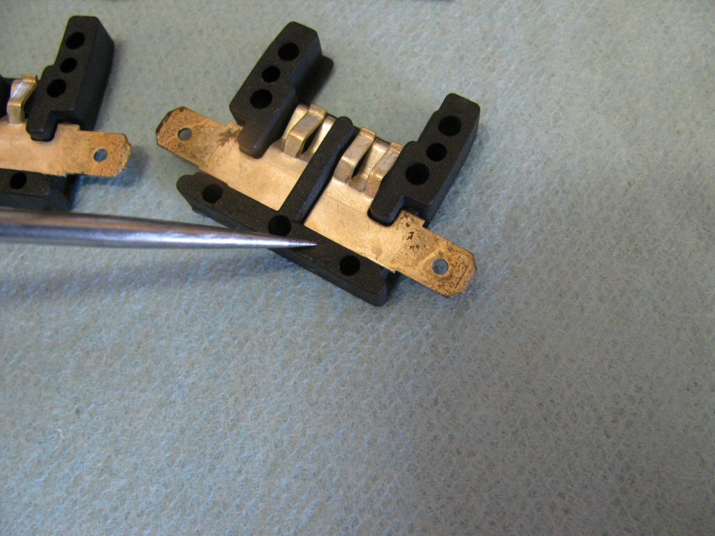
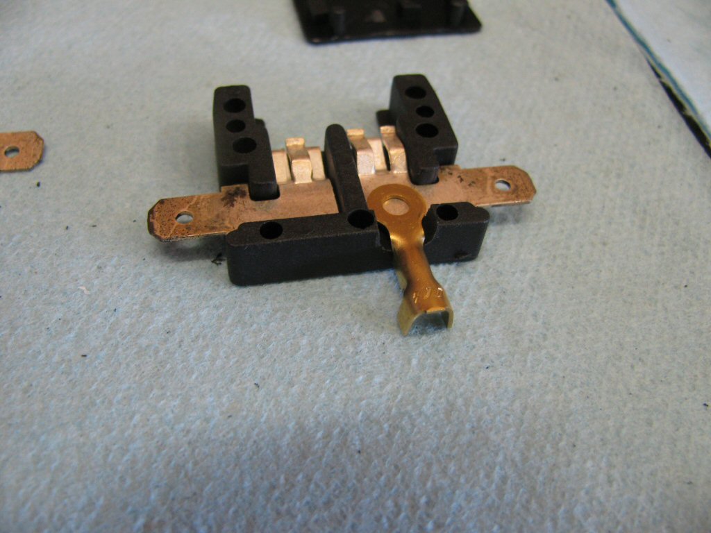
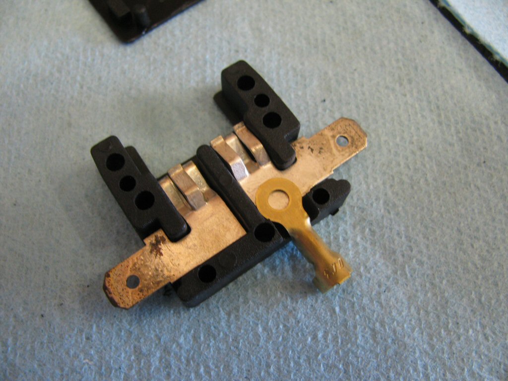
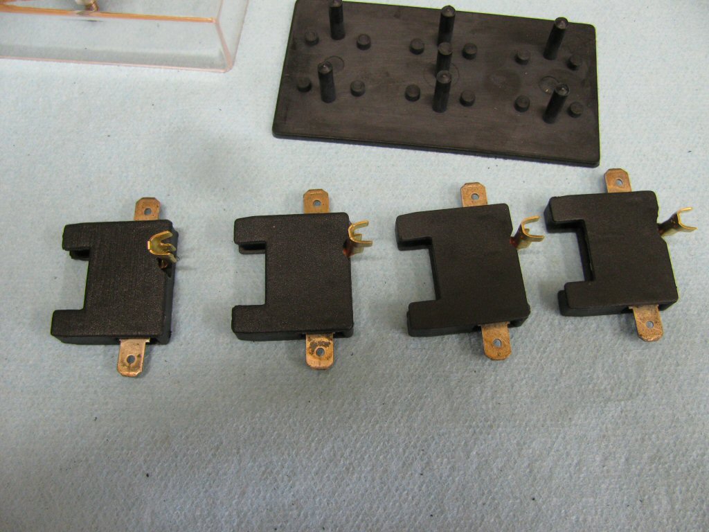
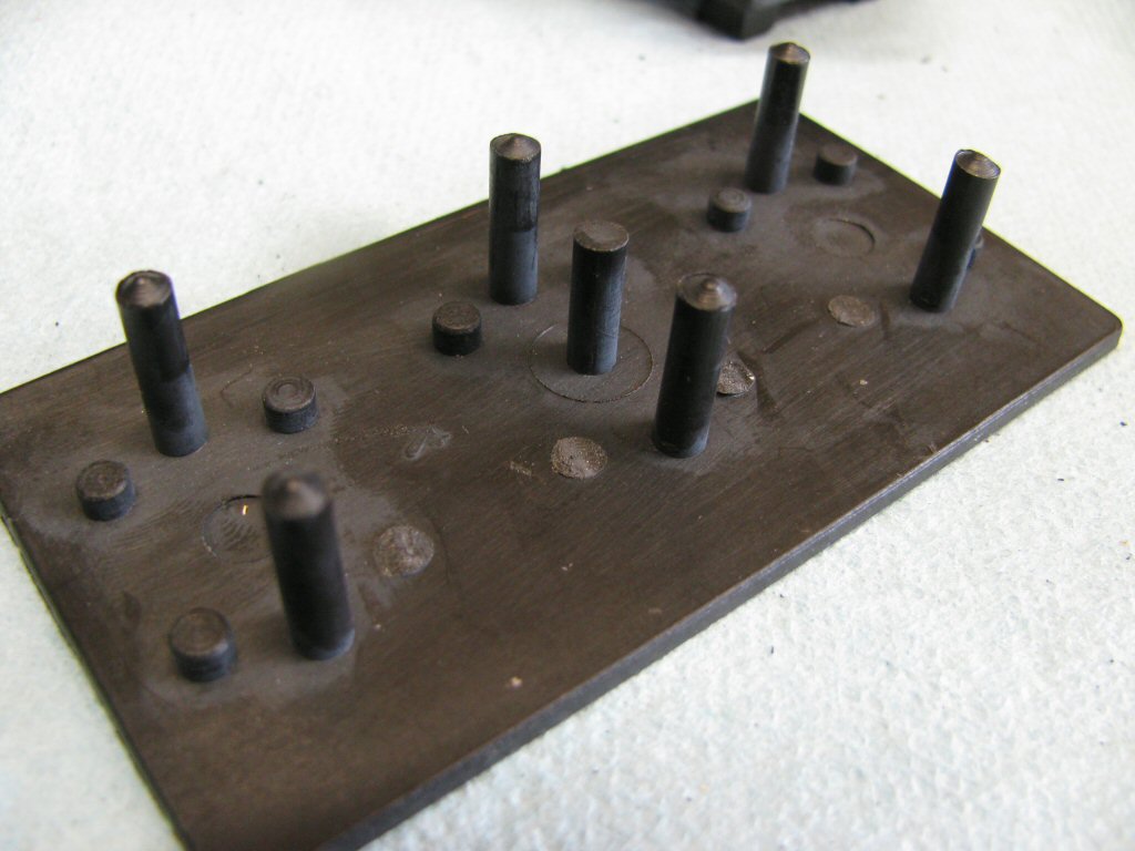
The photos below show my very first modification in which I joined the middle four top terminals. To work for both civilian and police applications, I now join the top two left terminals, the next three terminals, and leave the right most terminal unlinked.
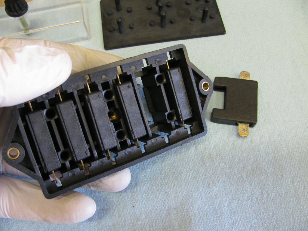
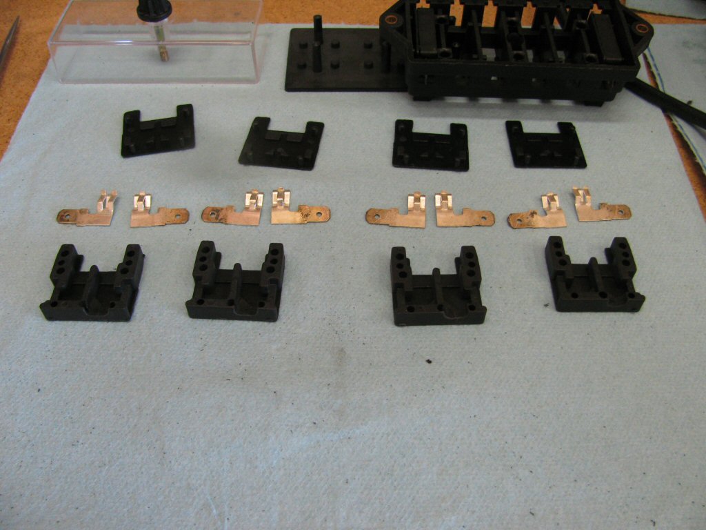
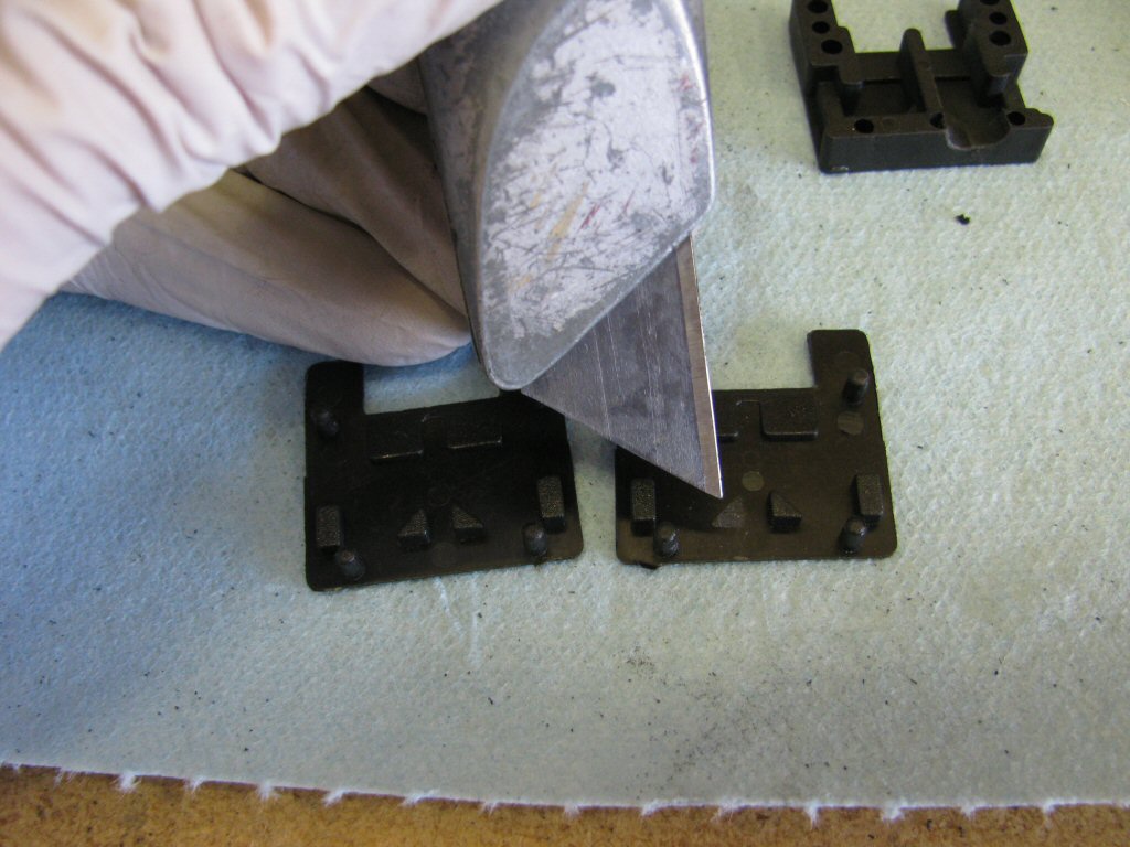
Start with the fuse box you purchased from Waytek.
Stephen Brenton's side cover fuse block (in his own words)
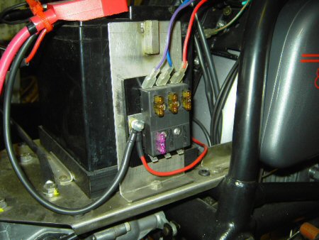
I remade the battery tray using 316SS. Then decided to attach an after market fuse panel to an upright leg, which also serves as a battery hold down. All this hides behind the (easily accessible) left side cover.
So far I've only got 3 leads from the fuse block, purple is horn, blue is headlights, red is ignition. (I made my wiring harness so I could do exactly what I wanted.)
Stephen Brenton's fuse block and battery hold down.
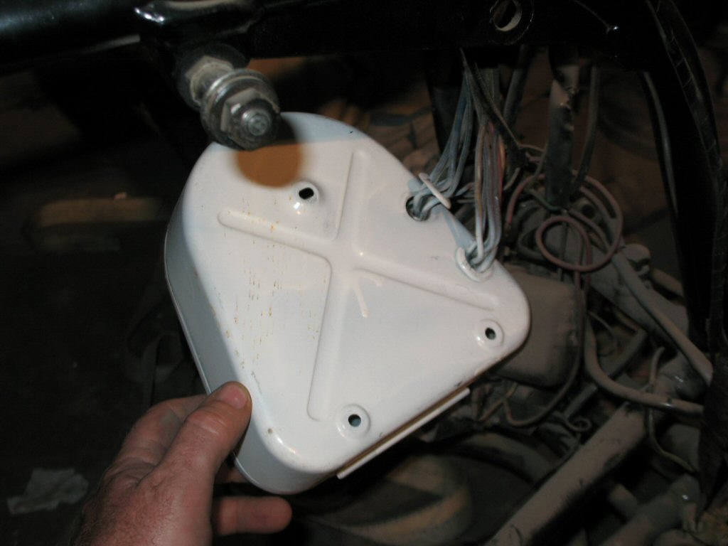
Tom Short sent me these photos of how the Phoenix Police Department relocated the fuse block.
Personally, I really do not like modifying the tool boxes in such a manner. It may seem like an improvement, but an original component is being permanently and destructively modified and more wiring is required to be run back and forth between the headlight and the tool box.