Siren bracket
Moto Guzzi V700, V7 Special, Ambassador, 850 GT, 850 GT California, Eldorado, and 850 California Police models
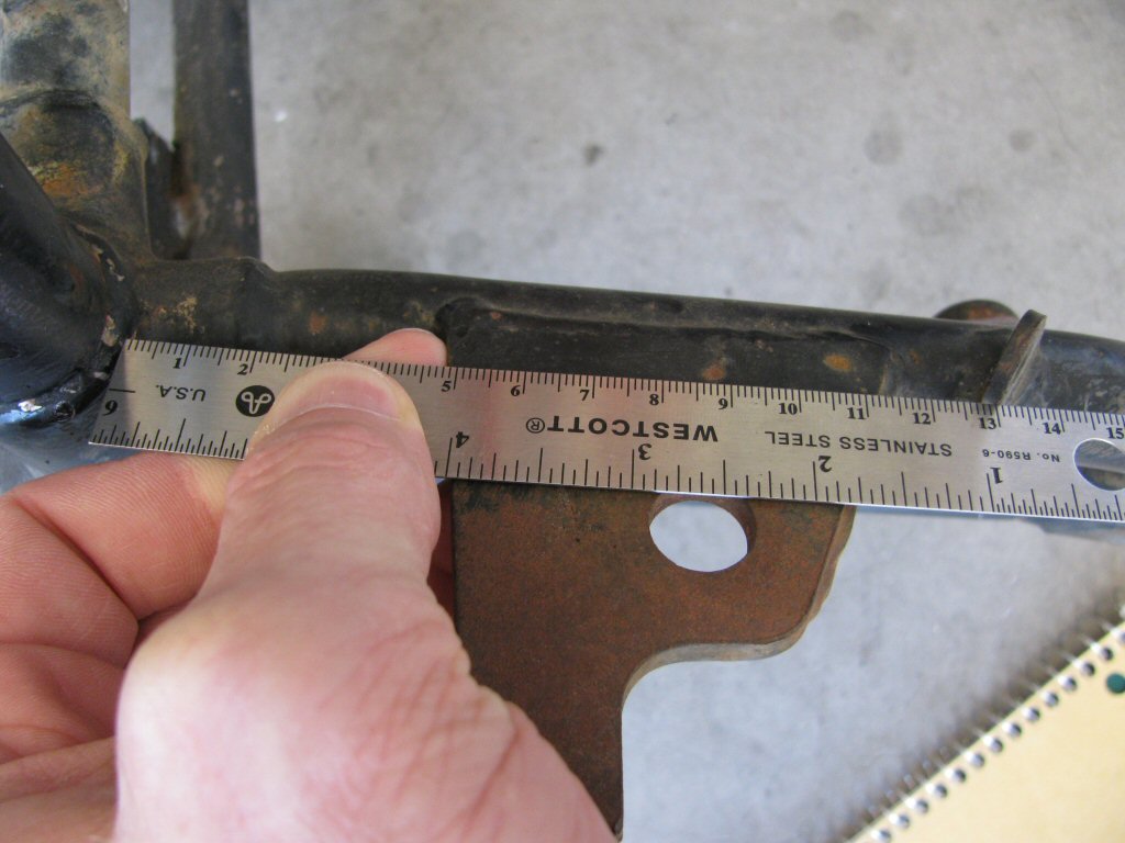
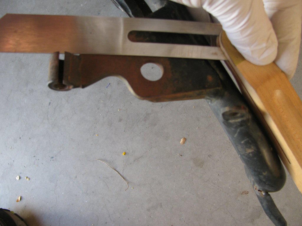
The siren bracket welded to the frame of some police frames appears as in the photos below. The bracket is made of steel, ~5 mm thick with a 14 mm diameter hole. Should you wish to add a siren bracket to your frame, please use the pattern I created below by tracing the outline of an original bracket.
Thanks to Bill Horribine for helping me identify the mount for the rubber pad (bumper).
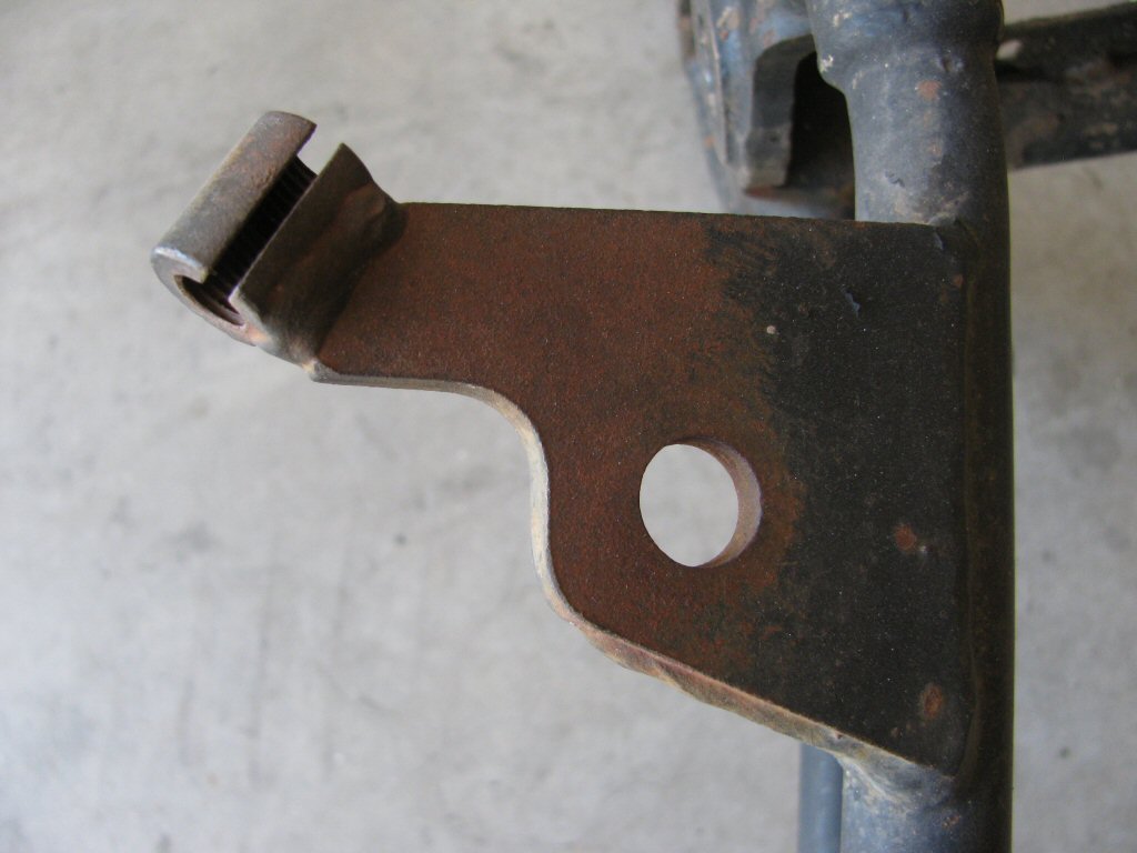
Photo courtesy of Gregory Bender.
baseis ~70 mm long.
Photo courtesy of Gregory Bender.
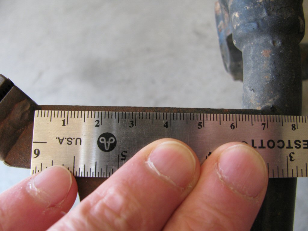
Photo courtesy of Gregory Bender.
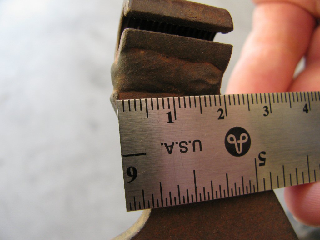
Photo courtesy of Gregory Bender.
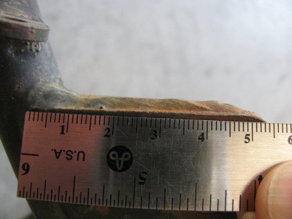
Photo courtesy of Gregory Bender.
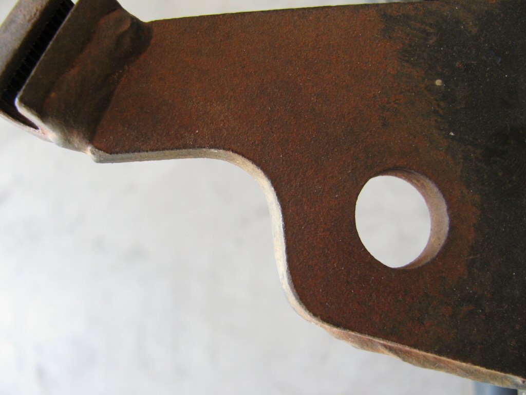
Photo courtesy of Gregory Bender.
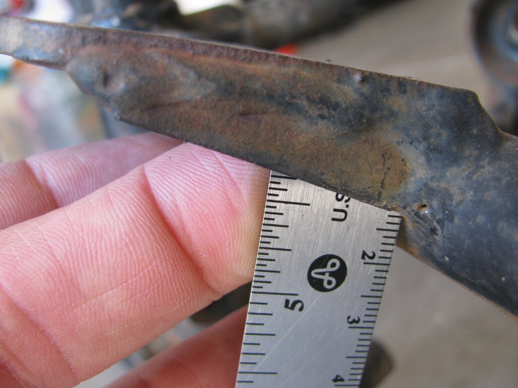
Photo courtesy of Gregory Bender.
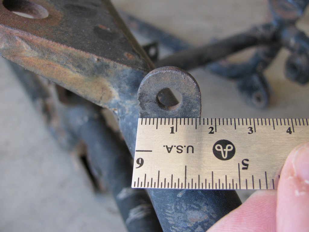
Photo courtesy of Gregory Bender.
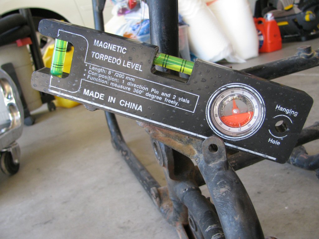
Photo courtesy of Gregory Bender.
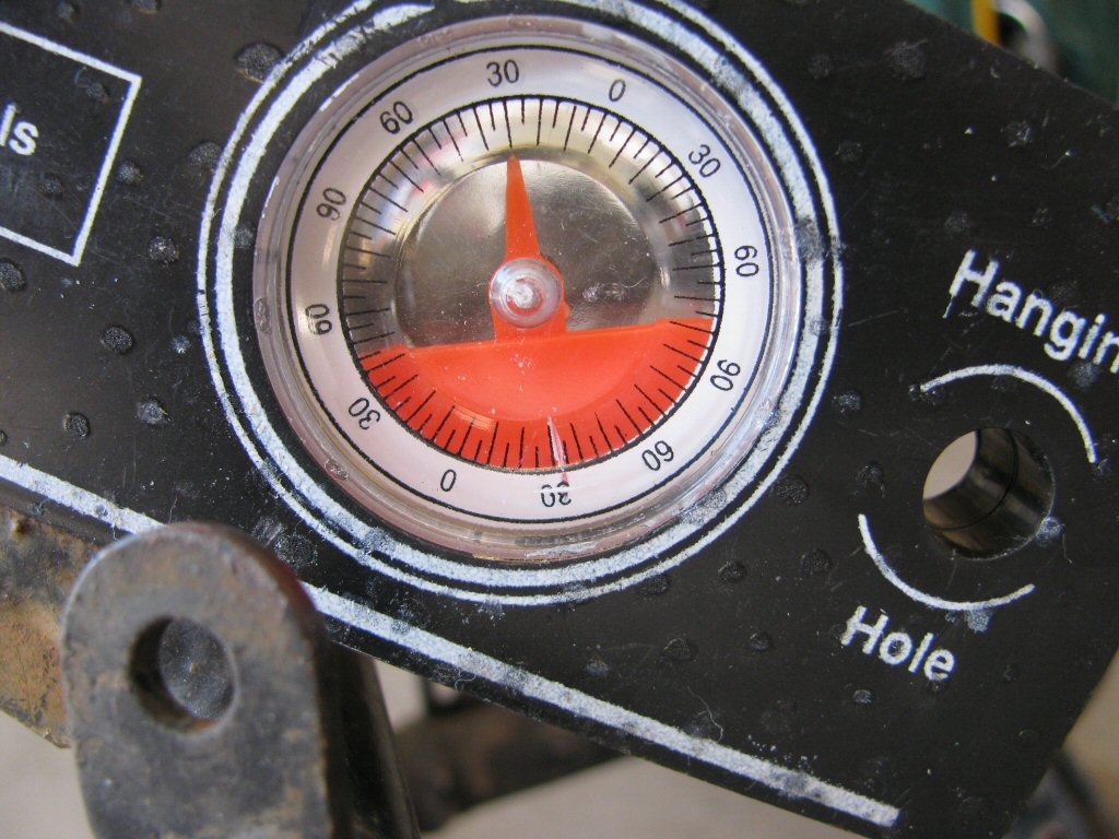
Photo courtesy of Gregory Bender.
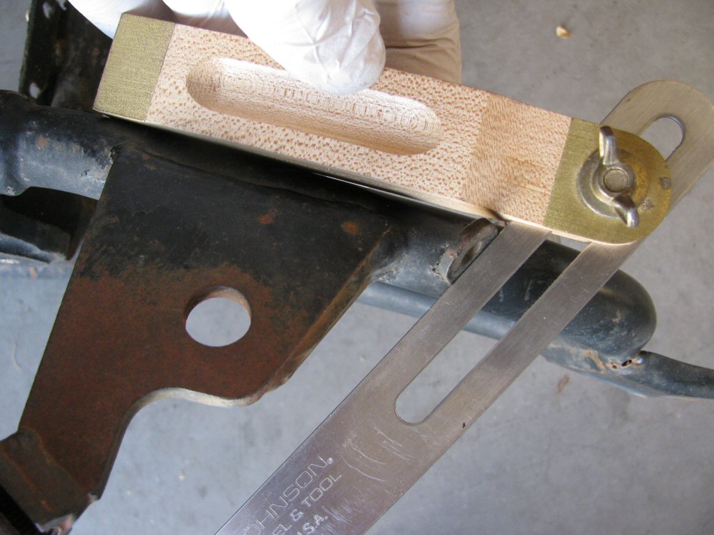
loop.
Photo courtesy of Gregory Bender.
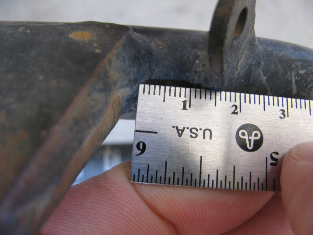
Photo courtesy of Gregory Bender.
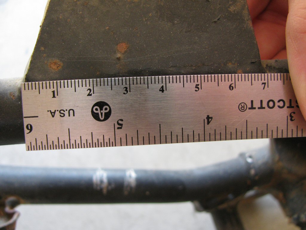
loop. Note that the angle of the mount for the rubber pad (bumper) is the same as the angle of the large cable bracket.
Photo courtesy of Gregory Bender.
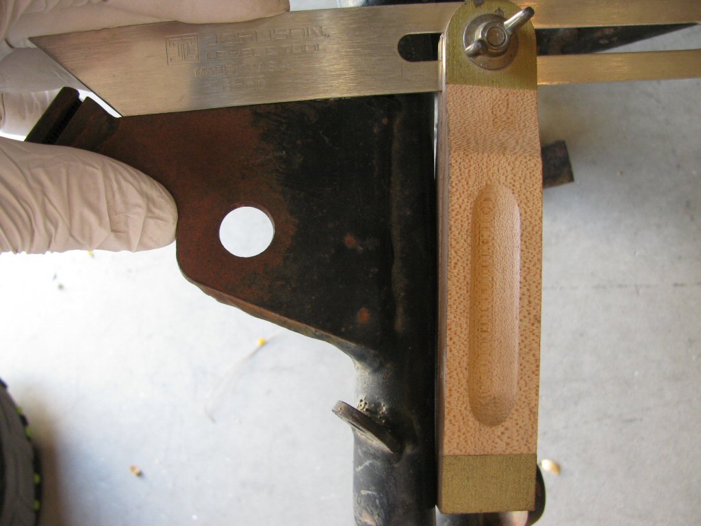
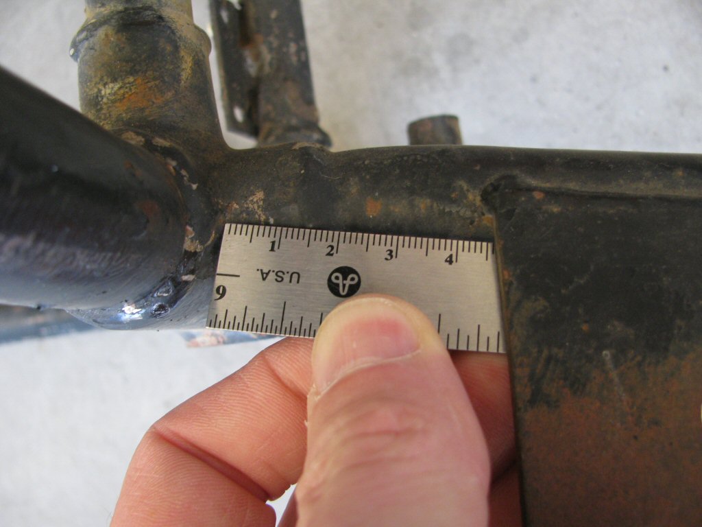
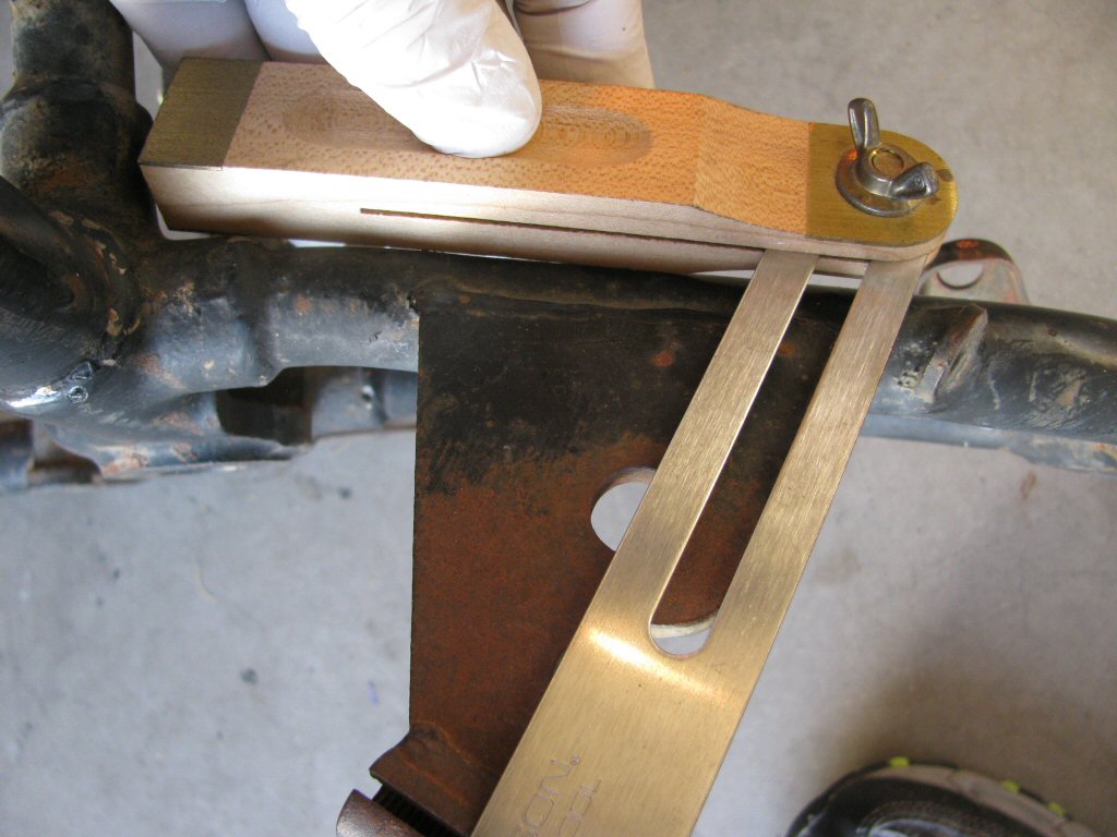
looppiece is not straight. When replicating, be careful to position your measuring device in a manner similar to how mine is photographed.
Photo courtesy of Gregory Bender.
looppiece is not straight. When replicating, be careful to position your measuring device in a manner similar to how mine is photographed.
Photo courtesy of Gregory Bender.
looppiece is not straight. When replicating, be careful to position your measuring device in a manner similar to how mine is photographed.
Photo courtesy of Gregory Bender.
looppiece is not straight. When replicating, be careful to position your measuring device in a manner similar to how mine is photographed.
Photo courtesy of Gregory Bender.
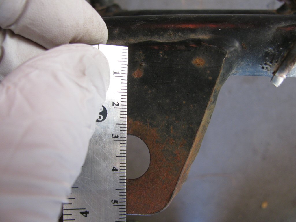
Photo courtesy of Gregory Bender.
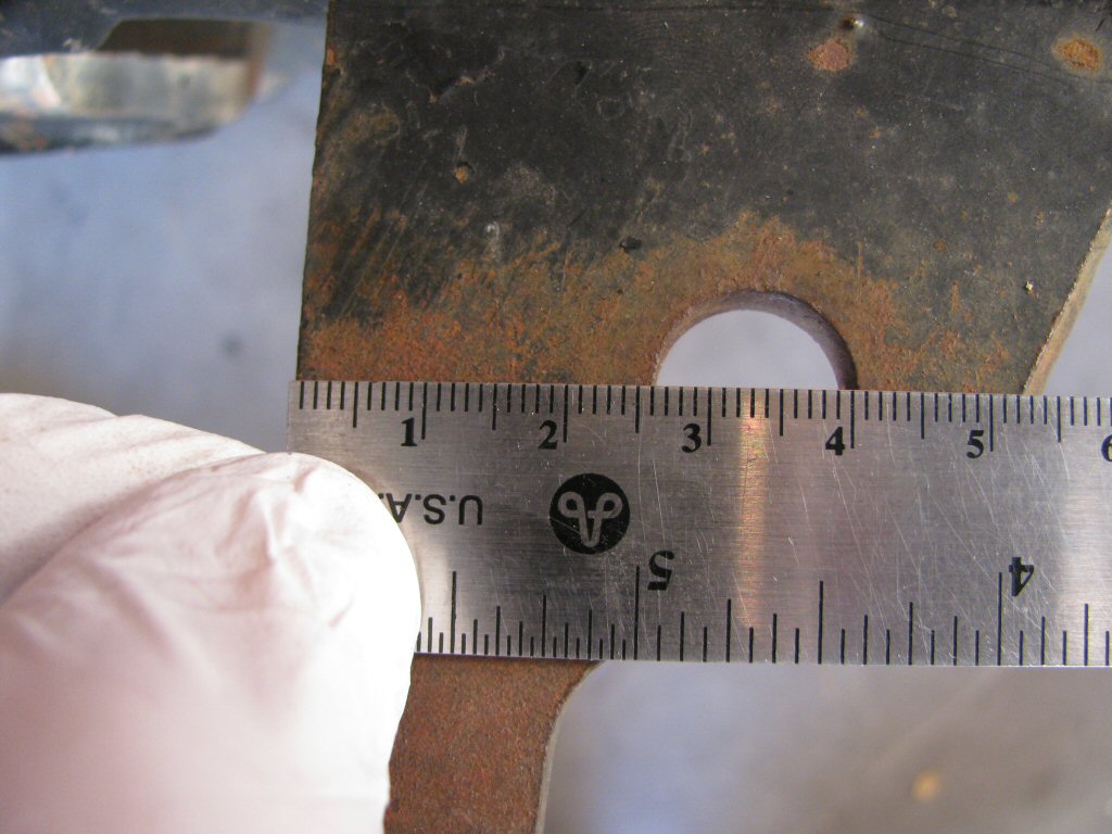
Photo courtesy of Gregory Bender.
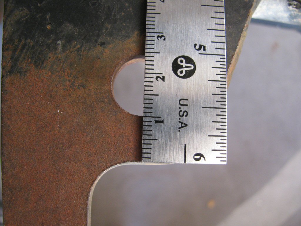
Photo courtesy of Gregory Bender.
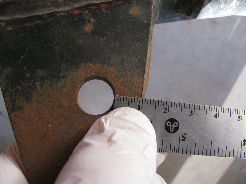
Photo courtesy of Gregory Bender.
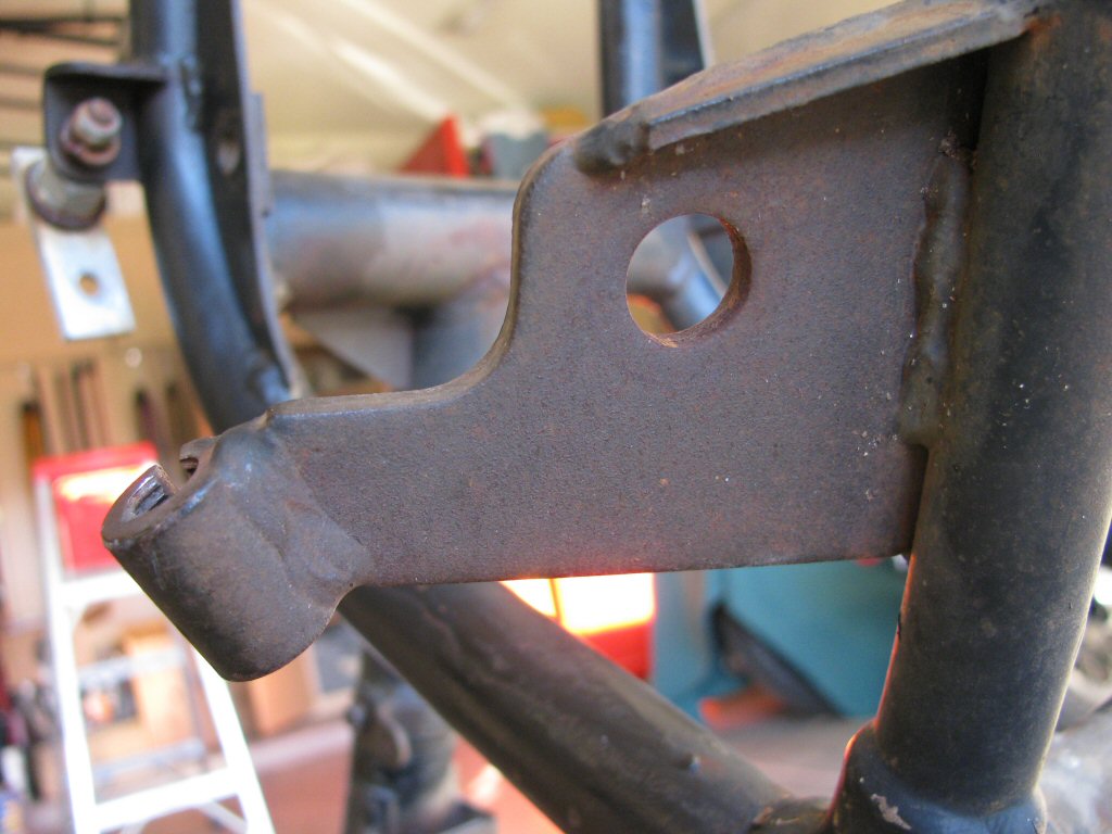
Photo courtesy of Gregory Bender.
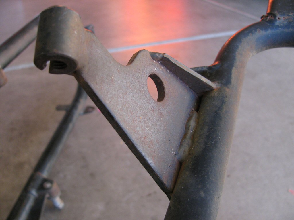
Photo courtesy of Gregory Bender.