Tool box lock rebuild
Moto Guzzi V700, V7 Special, Ambassador, 850 GT, 850 GT California, Eldorado, and 850 California Police models
Working on a customer's project bike, I encountered a nice set of tool box locks without any keys. Rather than pay a locksmith to do the work (my last locksmith bill for cutting a new key was far from inexpensive), I decided to figure out how to disassemble, clean, and rebuild the lock myself. With the lock apart, cutting a new key would be easy. Here is the step-by-step:
- Here is the original lock.
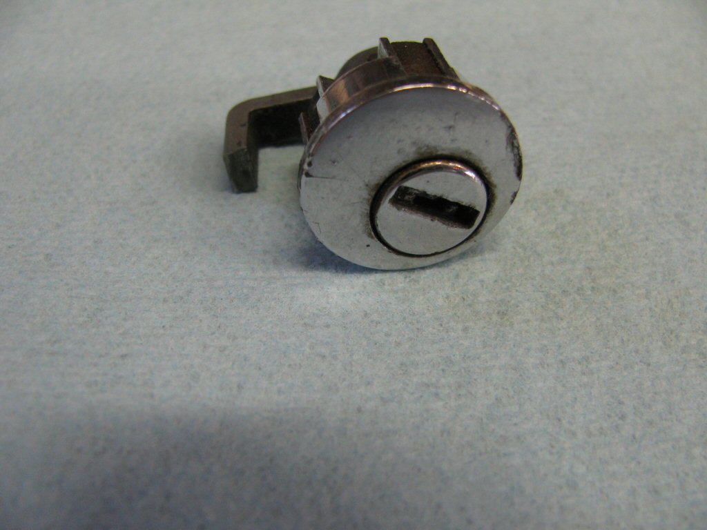
Photo courtesy of Gregory Bender.
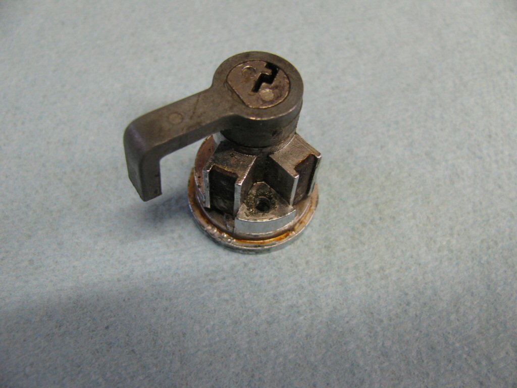
Photo courtesy of Gregory Bender.
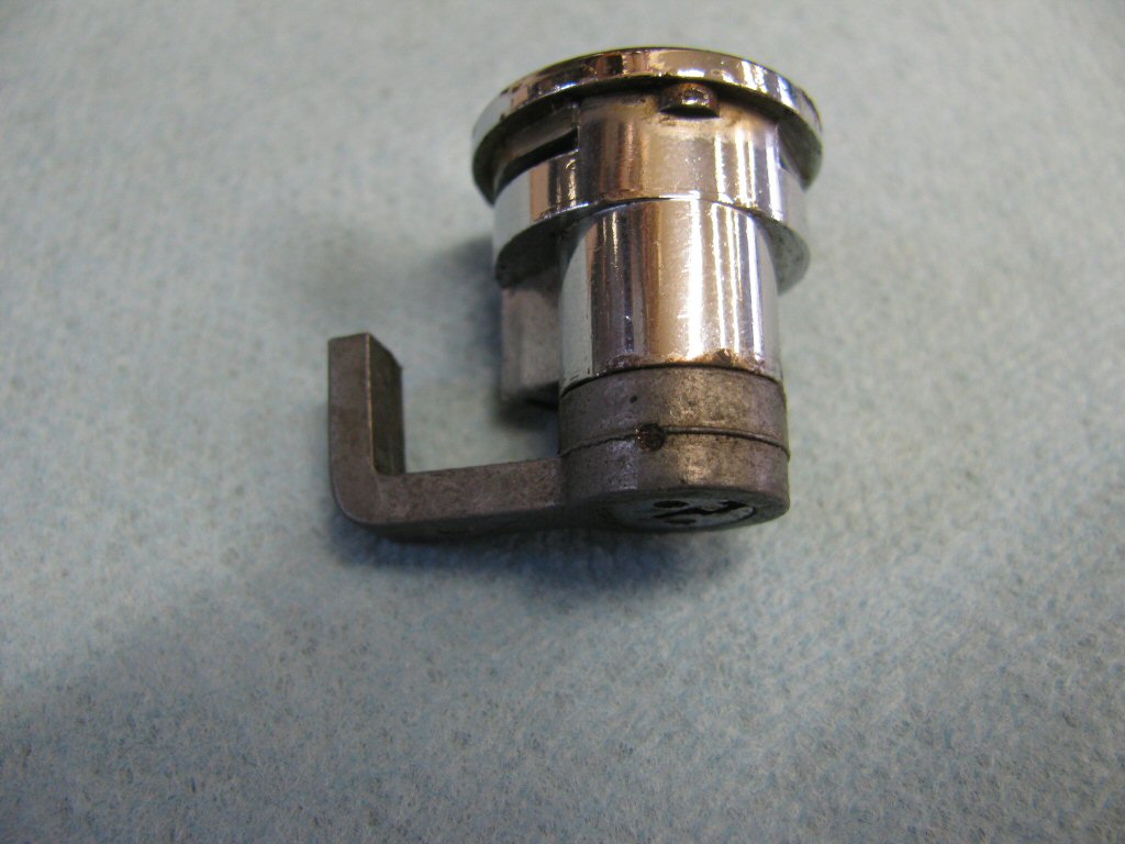
Photo courtesy of Gregory Bender.
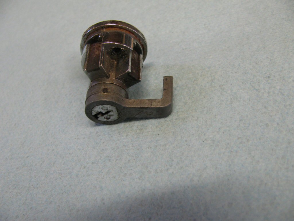
Photo courtesy of Gregory Bender.
- Start by using a small punch to carefully and gently drive out the pin. In my experience, the pin is not excessively tight. Drive it out just a little bit. Be sure the punch is small enough. You don't want to use too big of a punch that places stress on the surrounding metal and cracks it. It is best to perform all of this work in a very clean area with a large towel beneath your work surface. The large towel will help keep many small pieces for getting lost and cleanliness will help you find them should they wonder off into the other places. You will not be able to walk into your local hardware store and find replacement parts for these locks. So, be exceedingly careful not to loose any of the small parts.
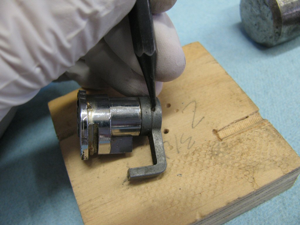
Photo courtesy of Gregory Bender.
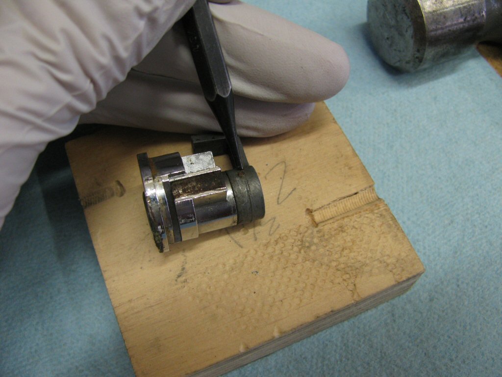
Photo courtesy of Gregory Bender.
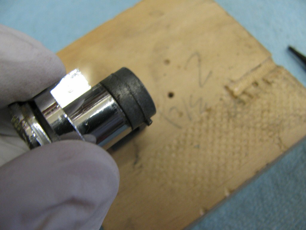
Photo courtesy of Gregory Bender.
- Use a pliers to grab and pull on the pin.
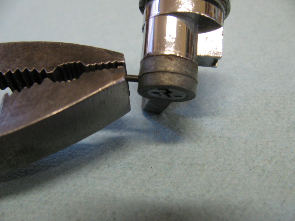
Photo courtesy of Gregory Bender.
- Pull it out just far enough that the pin is held in place by only the lever.
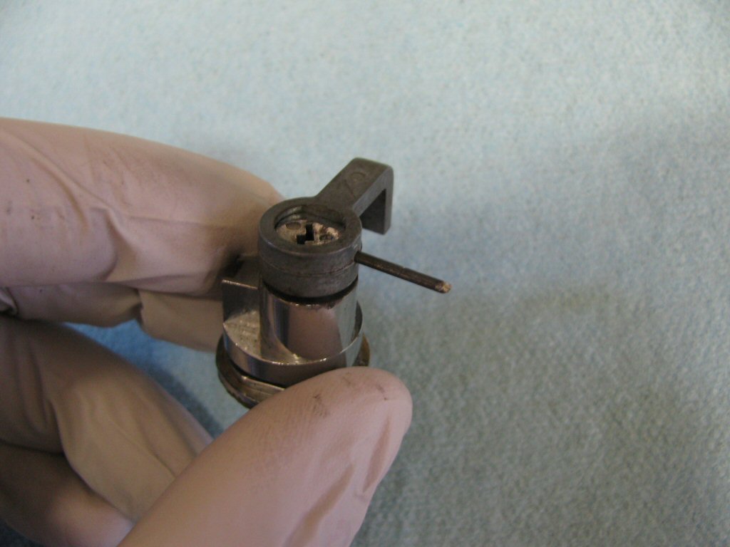
Photo courtesy of Gregory Bender.
- Slide the lever off the end and set it aside.
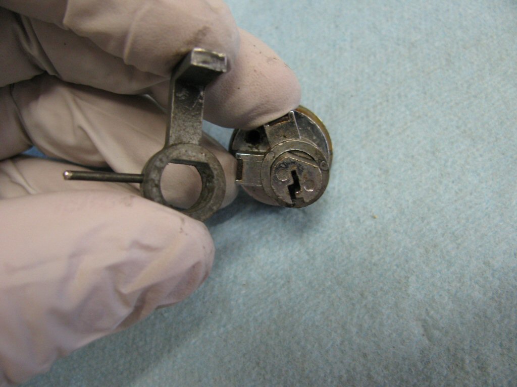
Photo courtesy of Gregory Bender.
- Turn your attention to the small metal covers. There are two covers. We will start by working with one cover and leave the other one alone for now. I like to start with the cover to which the key slot is pointing.
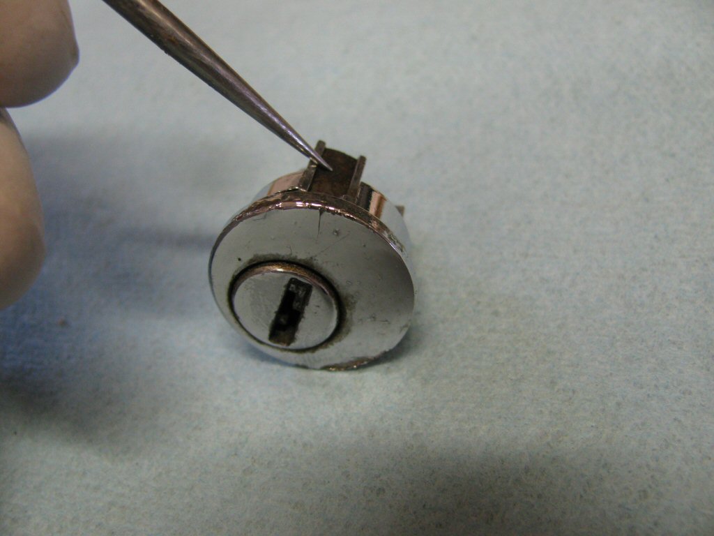
Photo courtesy of Gregory Bender.
- Use a small screwdriver to carefully pry the cover away from the front of the lock.
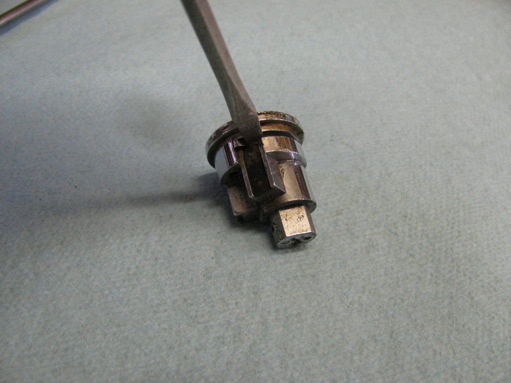
Photo courtesy of Gregory Bender.
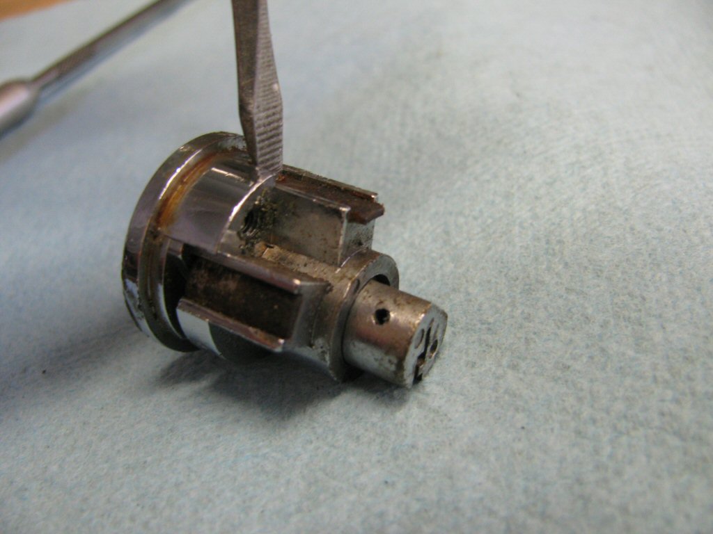
Photo courtesy of Gregory Bender.
- As you slide the cover away, you will expose the first of four springs and eight pins under this cover.
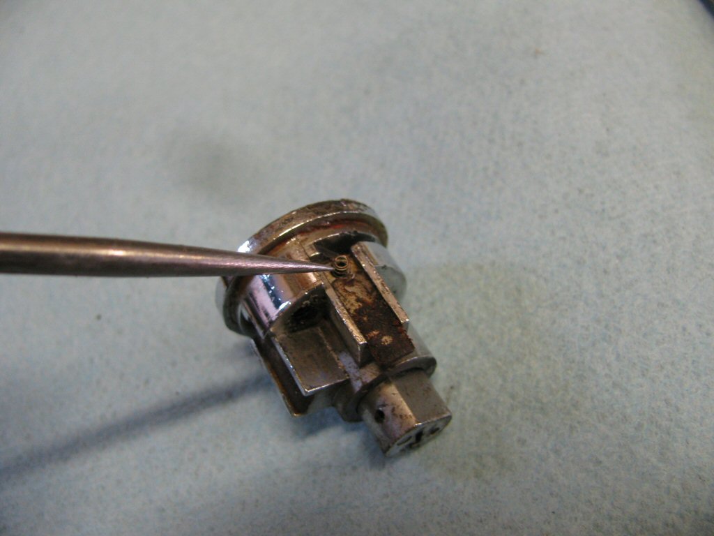
Photo courtesy of Gregory Bender.
- Withdraw the spring and the first pin. I discovered this pin to be 2.5 mm in length. The remaining three pins were 2 mm in length. You will want to keep the pins organized as you remove them.
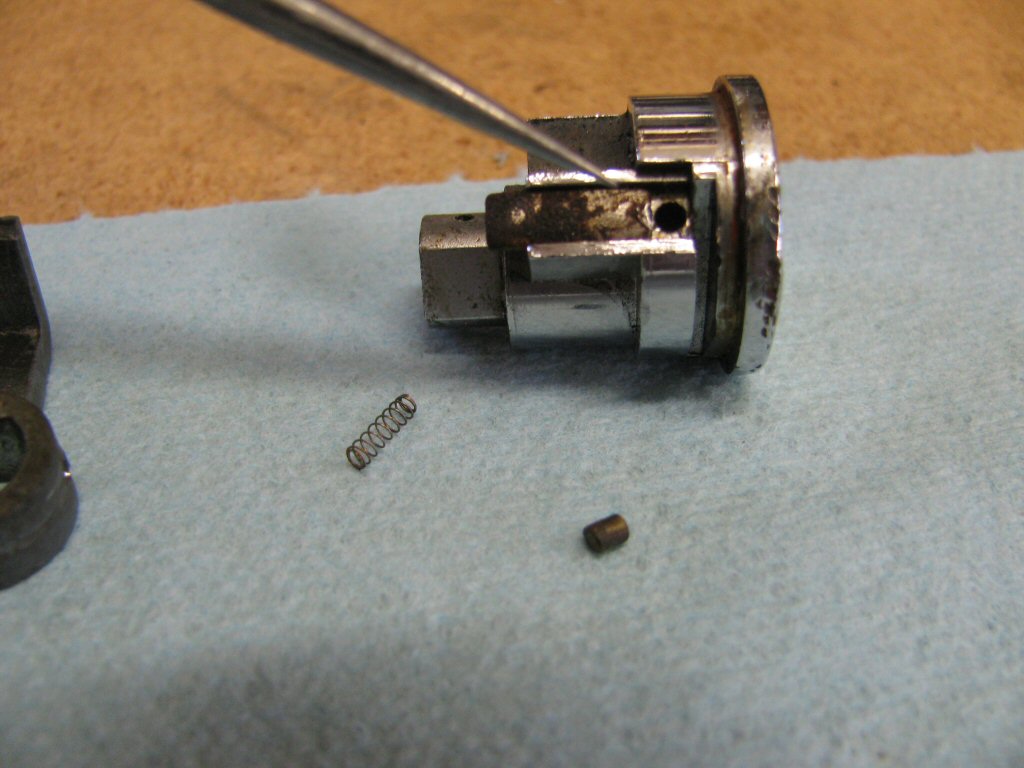
Photo courtesy of Gregory Bender.
- There is another pin below this first pin. Remove it as well. I found a small paper clip worked well to push it up from the key way...then I would tap it on the table until it dropped out. While you do this, be careful that you do not dislodge the cover completely. If you do, all of the other springs and pins will likely go flying.
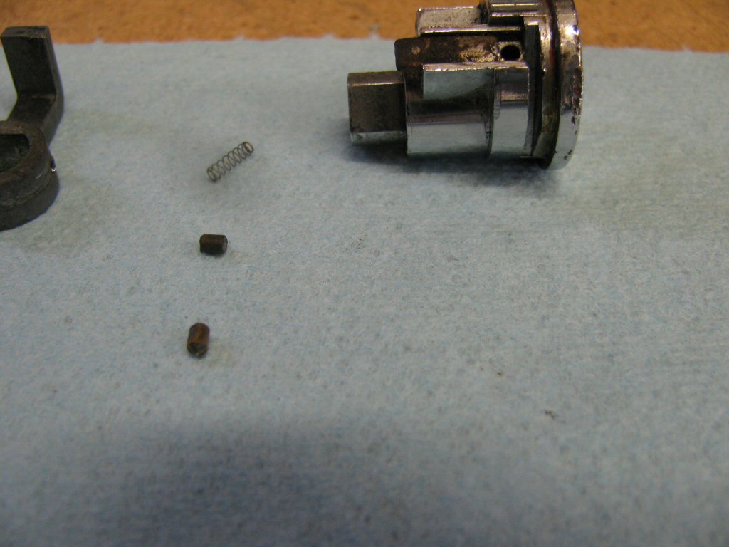
Photo courtesy of Gregory Bender.
- Now slide the cover back to expose the next spring.
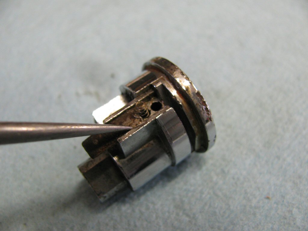
Photo courtesy of Gregory Bender.
- Remove the spring and the next two pins.
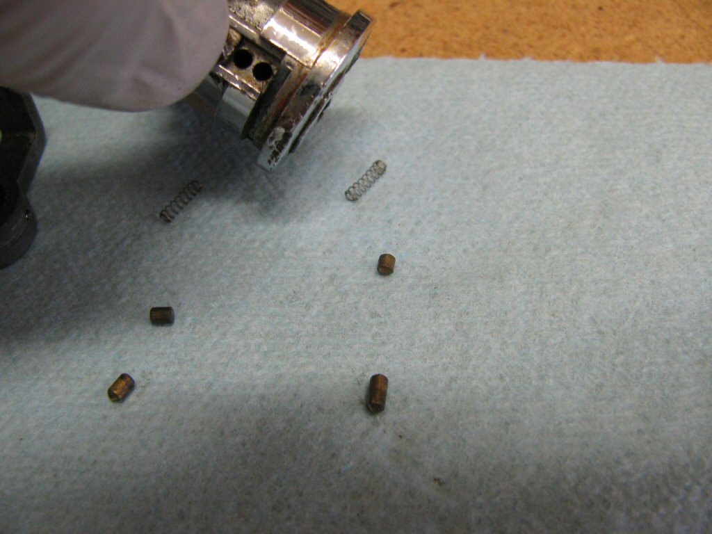
Photo courtesy of Gregory Bender.
- At this point, the cover will likely want to slide off completely. If it does, remove it carefully and keep your fingers over the springs.
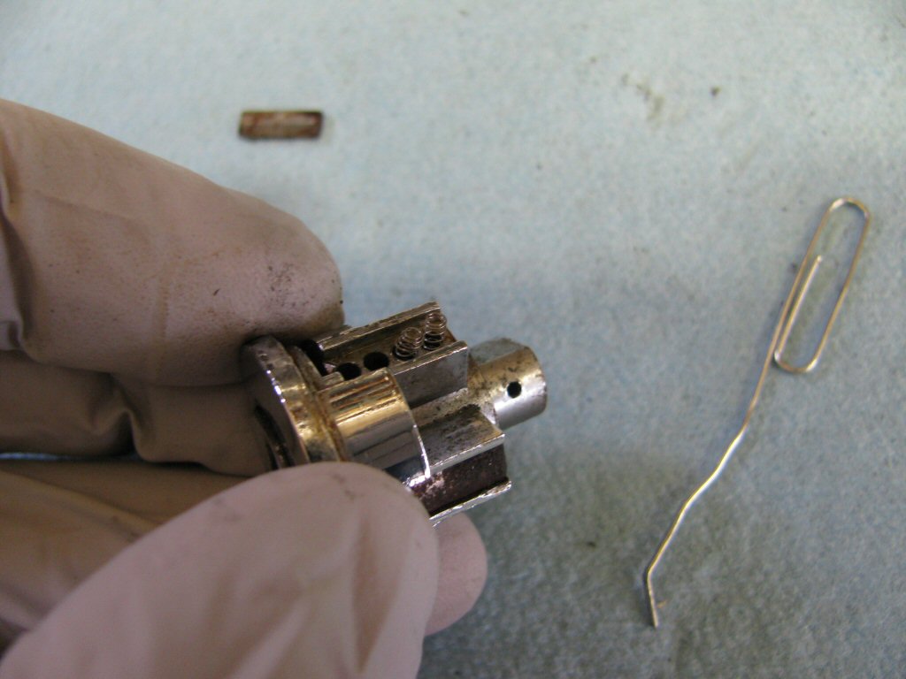
Photo courtesy of Gregory Bender.
- Remove the third spring and both pins.
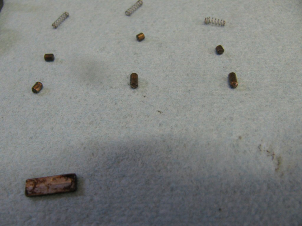
Photo courtesy of Gregory Bender.
- Remove the fourth spring and both pins. With the fourth pin removed, the core of the lock will be completely free to slide out of the lock body. You should be aware, however, that under the other small metal cover lives four more springs and four more short pins. If you remove the core of the lock from the lock body, the springs will push the pins out completely and they can easily become lost. For this reason, I like to remove the other cover in exactly the same manner as the first cover. Instead of two sets of pins in each hole, however, there will only be one set of pins.
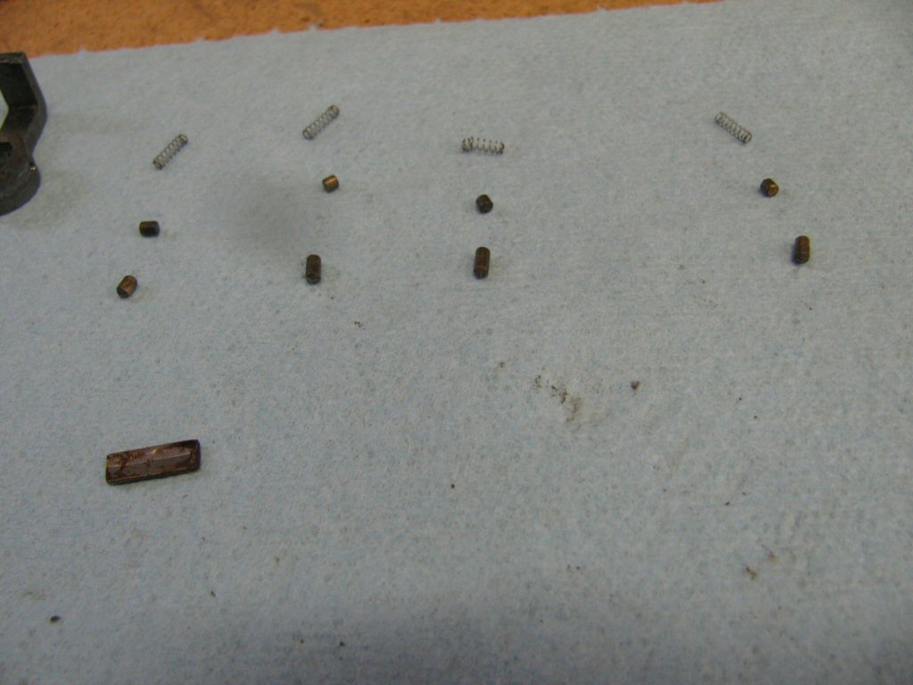
Photo courtesy of Gregory Bender.
- The body of the lock with both covers removed and emptied of all pins and springs.
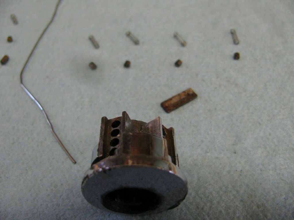
Photo courtesy of Gregory Bender.
- The core of the lock with no pins. The pins that fit in the lock are the ones placed immediately above the core. These pins are longer than the other four pins and have a tapered end to ease key entry and withdrawal.
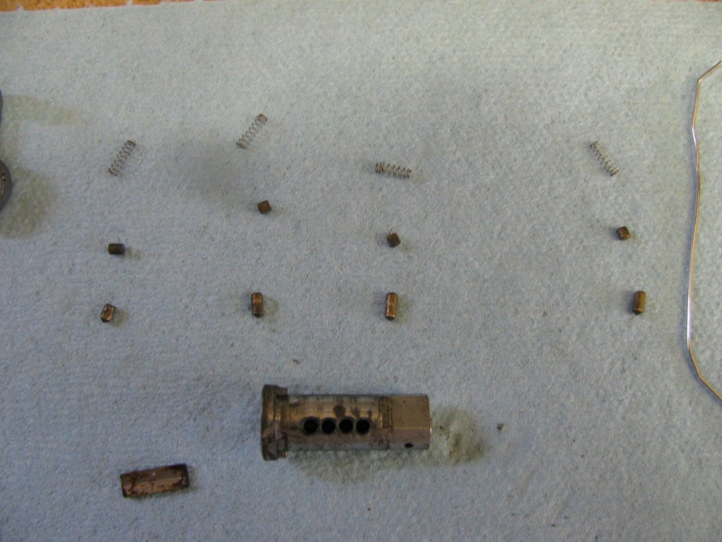
Photo courtesy of Gregory Bender.
- Here is the core with a blank key.
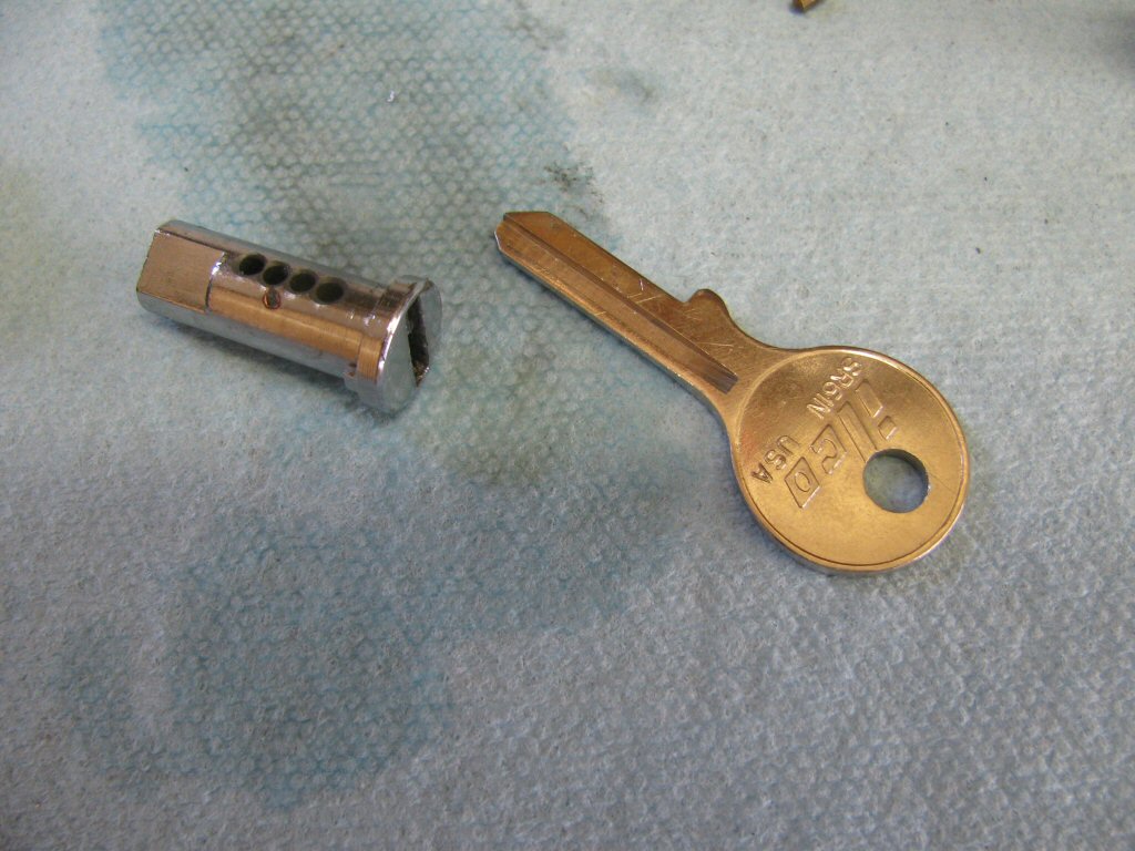
Photo courtesy of Gregory Bender.
- Insert the key into the core.
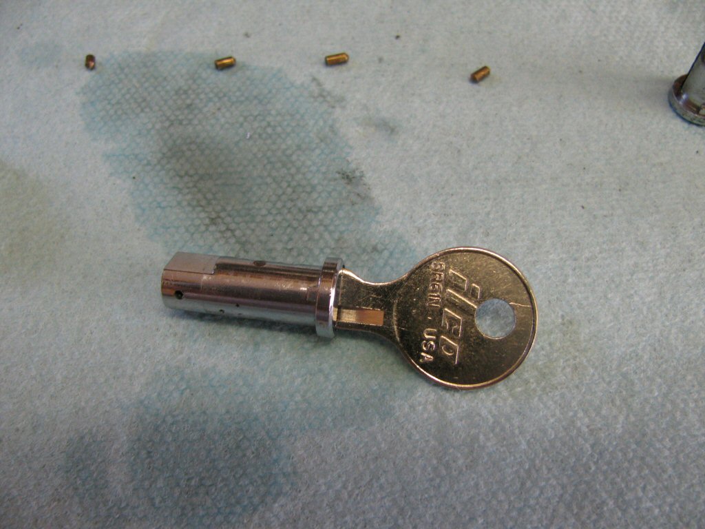
Photo courtesy of Gregory Bender.
- Temporarily place the pins in the core. Notice the pins stick up above the core. This is because the key has not yet been cut. Once the key is properly cut, the pins will be level with the core when the key is inserted.
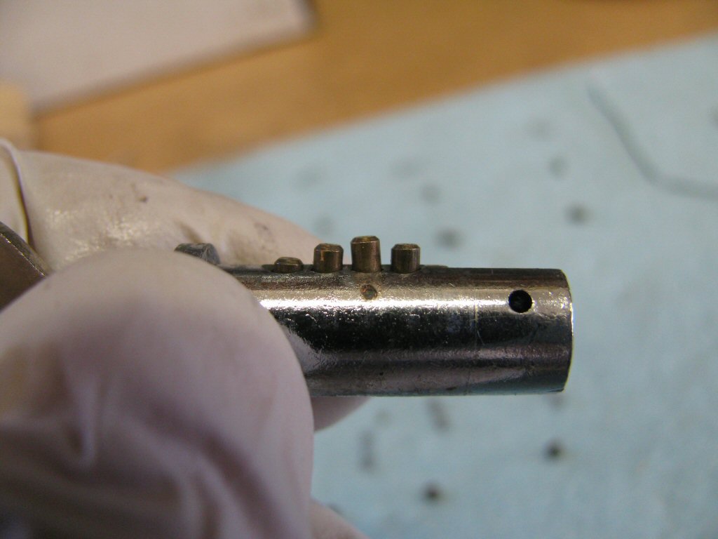
Photo courtesy of Gregory Bender.
- When the key is withdrawn, the springs from the lock body will push the outer set of pins against the pins that remain in the lock core. The pins will then prevent the lock from rotating.
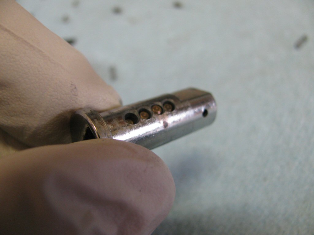
Photo courtesy of Gregory Bender.
- It is time to cut the key. I started by coating the surface to be cut with some dye-chem.
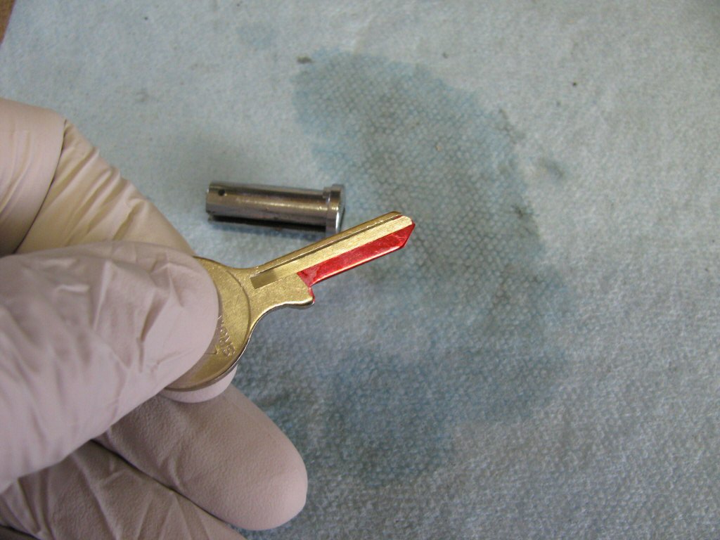
Photo courtesy of Gregory Bender.
- Then I inserted the key into the core of the lock.
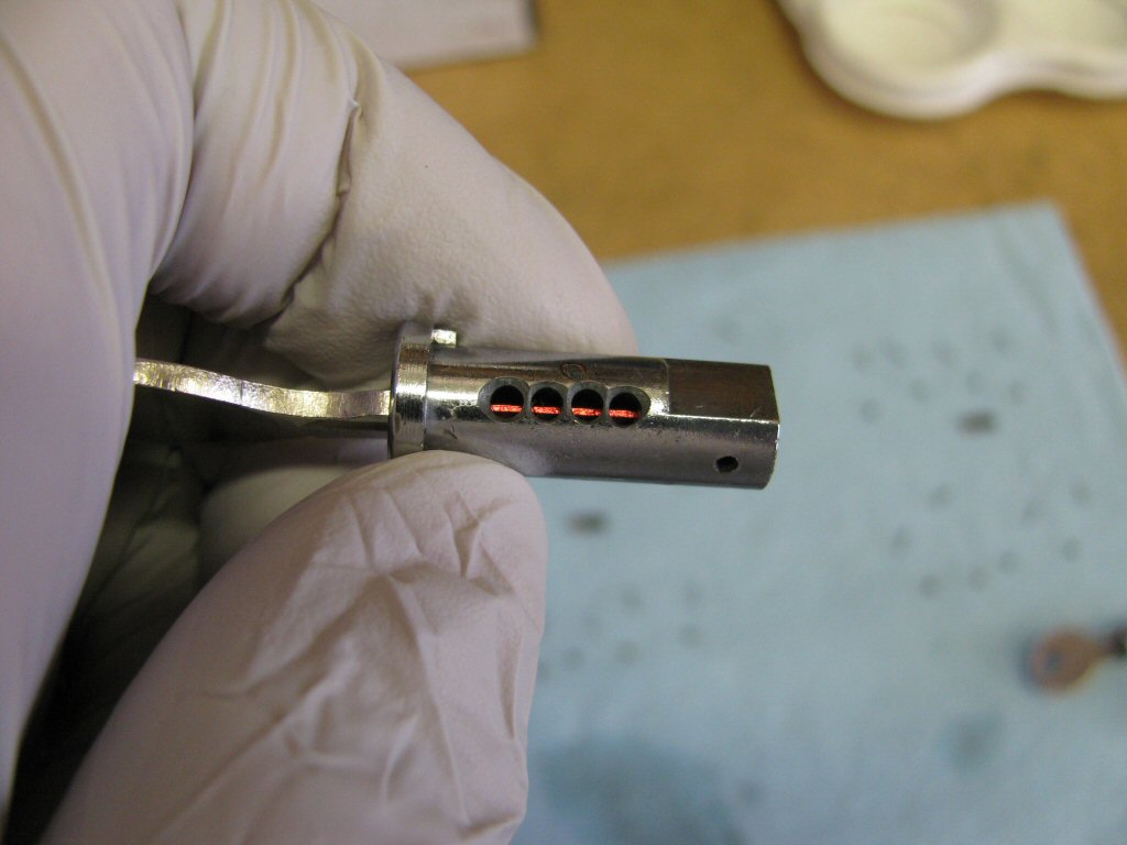
Photo courtesy of Gregory Bender.
- And scraped away the dye chem.
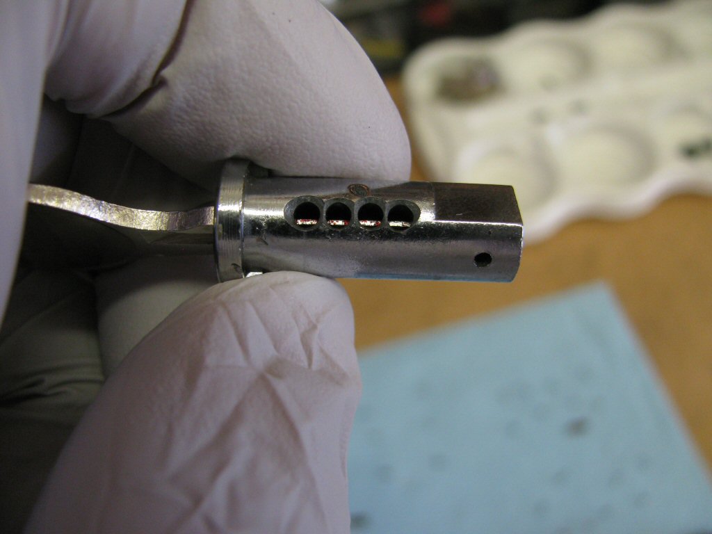
Photo courtesy of Gregory Bender.
- Which left me with the four locations that I needed to file in order to cut the key.
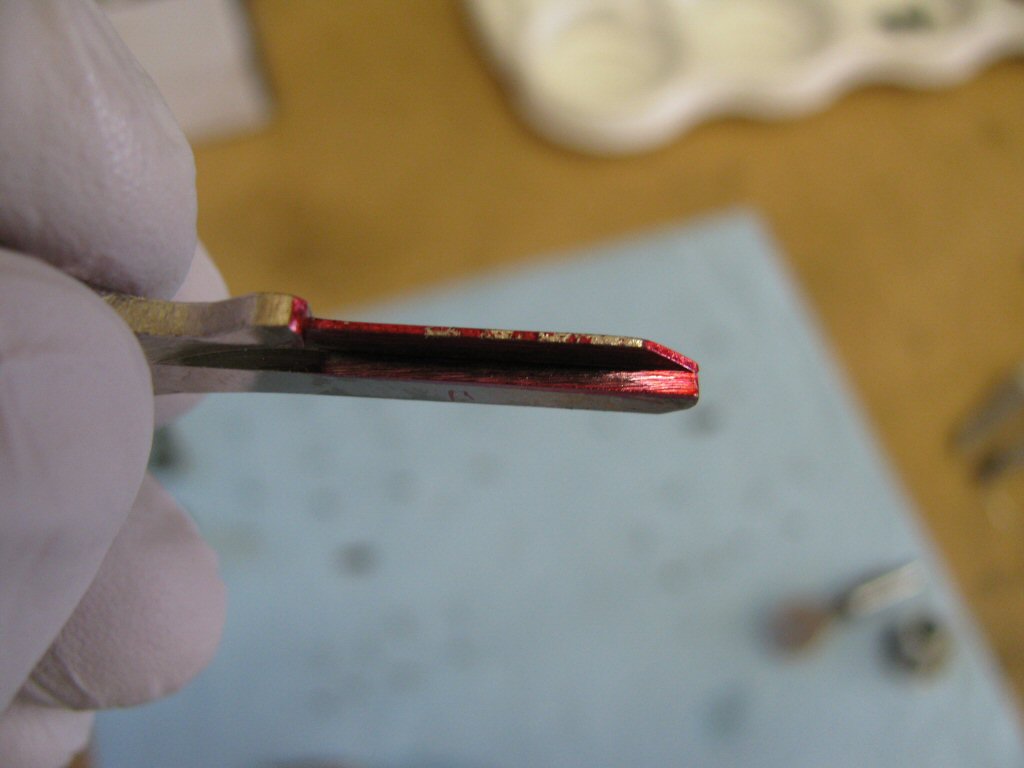
Photo courtesy of Gregory Bender.
- After a bit of work cutting the key I got to the point where my pins were even with the surface of the core. Cut the key in small increments. It is very easy to remove too much metal and the key is ruined. Always test the key with the core inserted into the body of the lock.
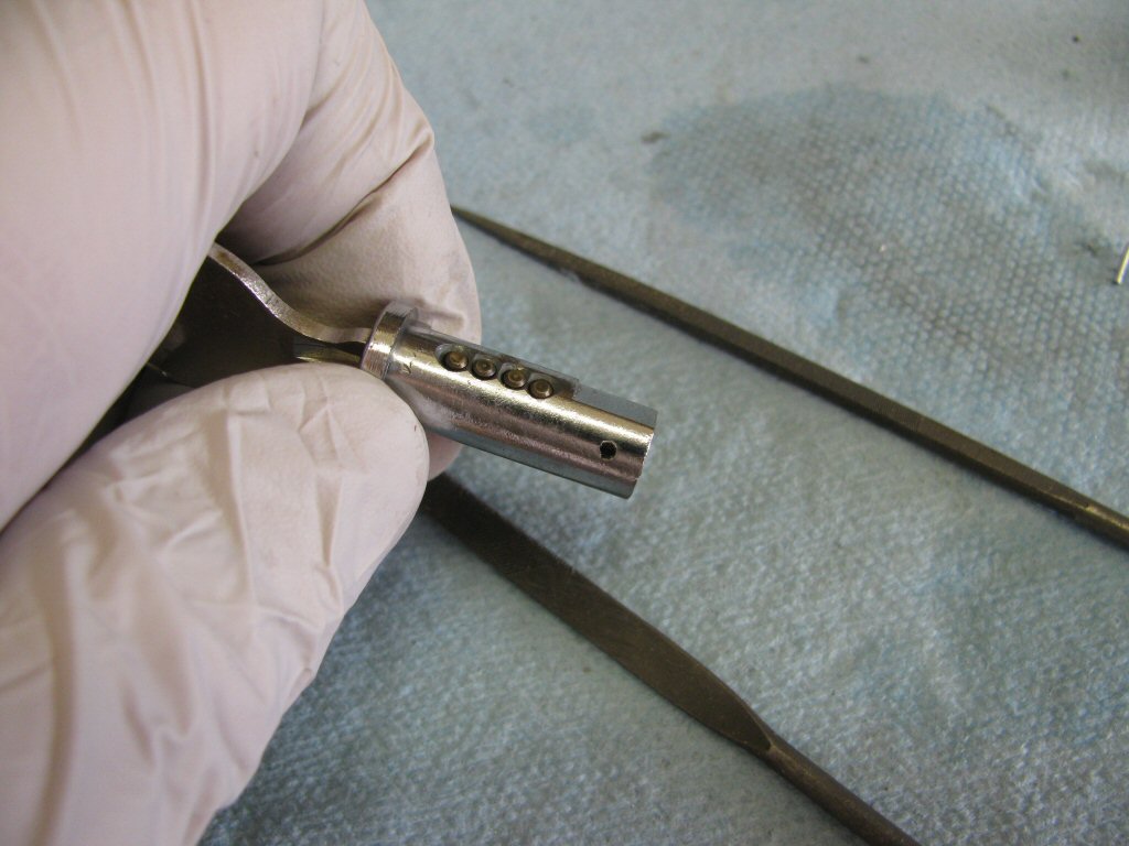
Photo courtesy of Gregory Bender.
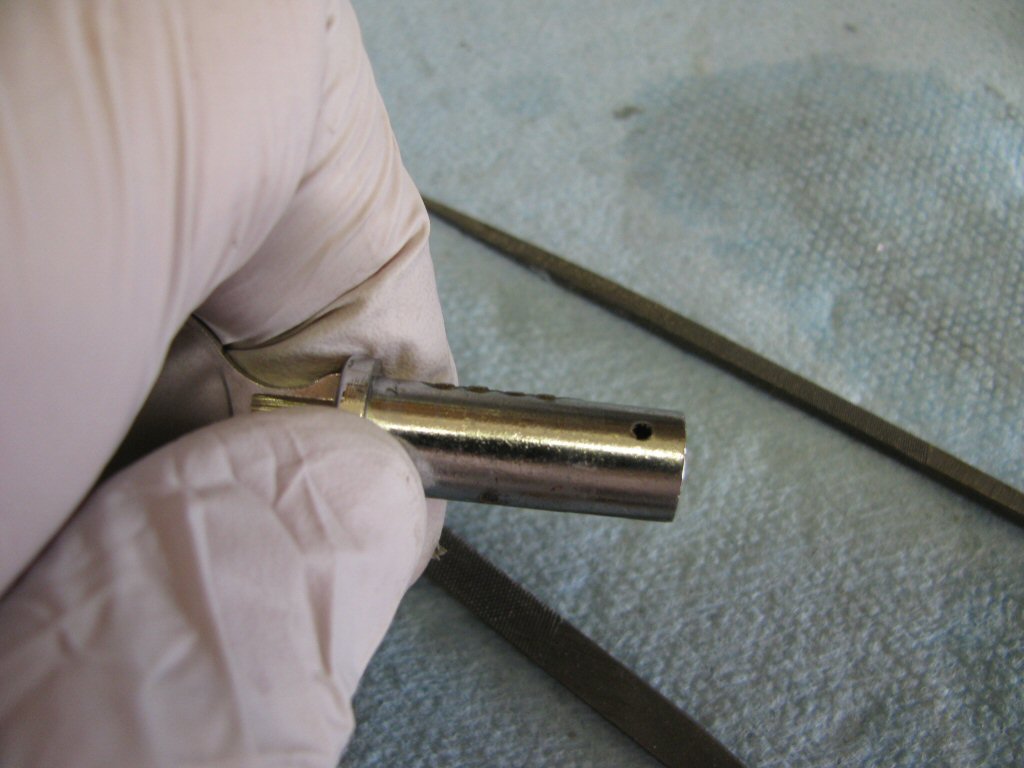
Photo courtesy of Gregory Bender.
- Here is the initial profile of the key. Note that the sides of each cut are square.
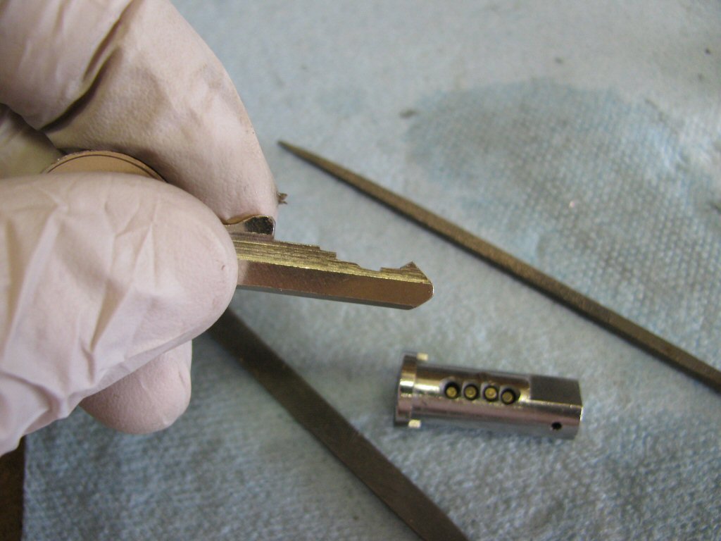
Photo courtesy of Gregory Bender.
- I've now filed 45° angles on the side of each cut. Doing this creates
ramps
that greatly ease the key into and out of the slot.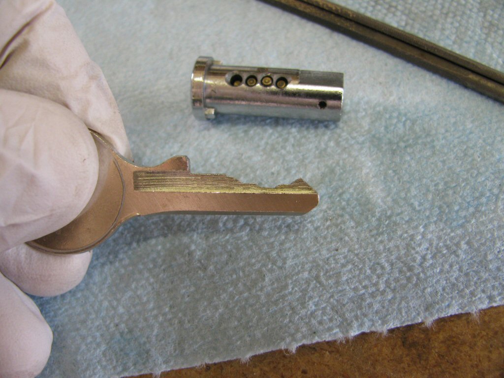
Photo courtesy of Gregory Bender.
- Time for reassembly. By this time you should be pretty familiar with the lock and it's operation. So, insert the core with it's pins and then replace the
outer
pins and springs.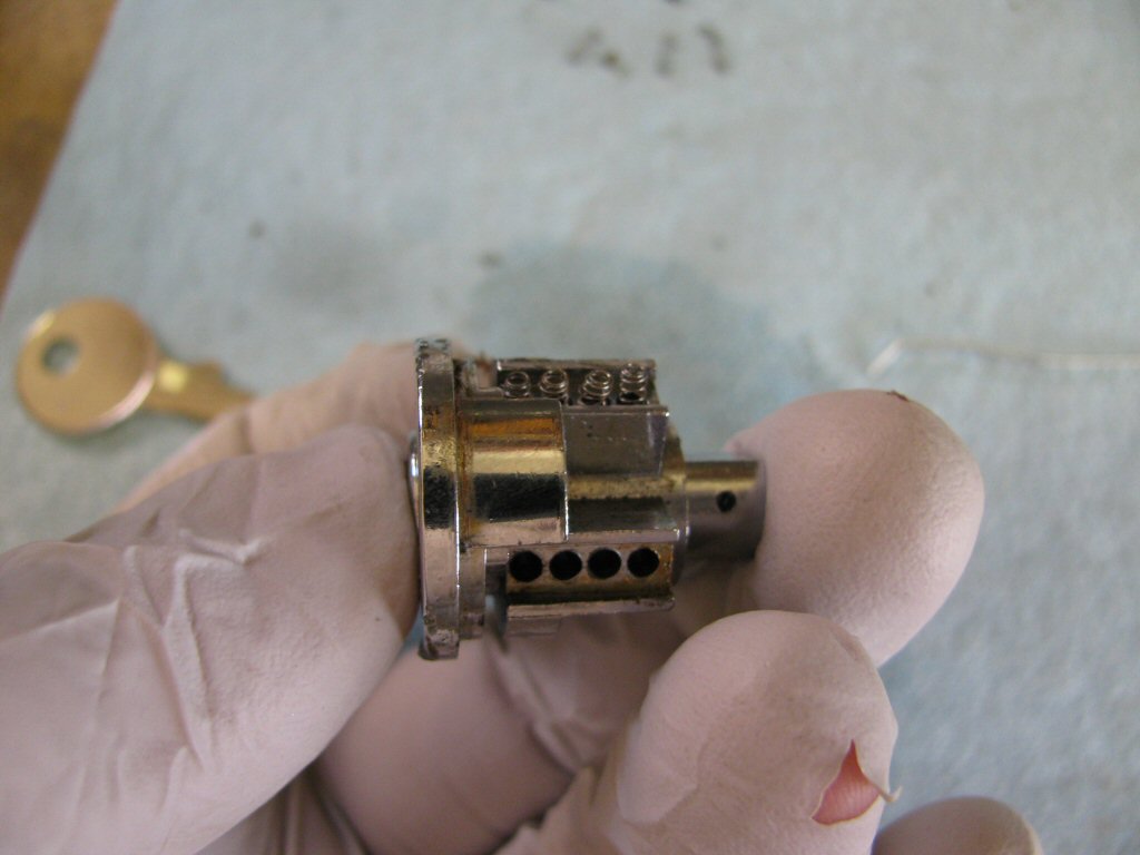
Photo courtesy of Gregory Bender.
- Replace the metal cover and gently tap it back in place with a small punch and hammer. There should be a light interference fit.
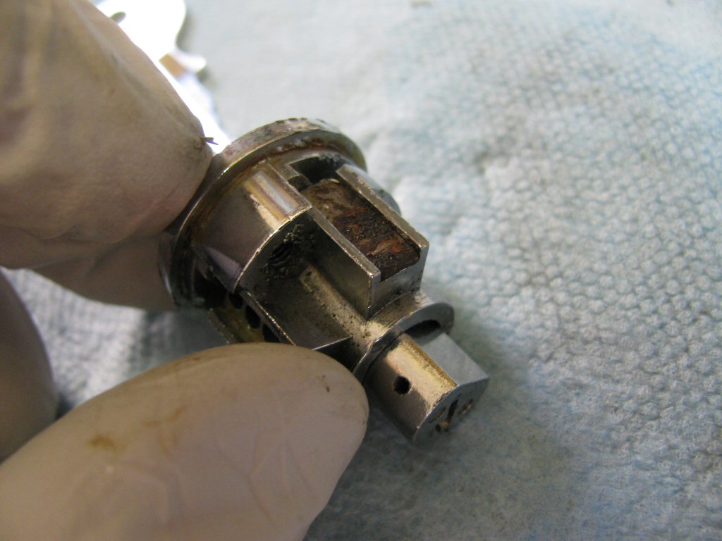
Photo courtesy of Gregory Bender.
- Repeat with the other set of outer pins, springs, and cover.
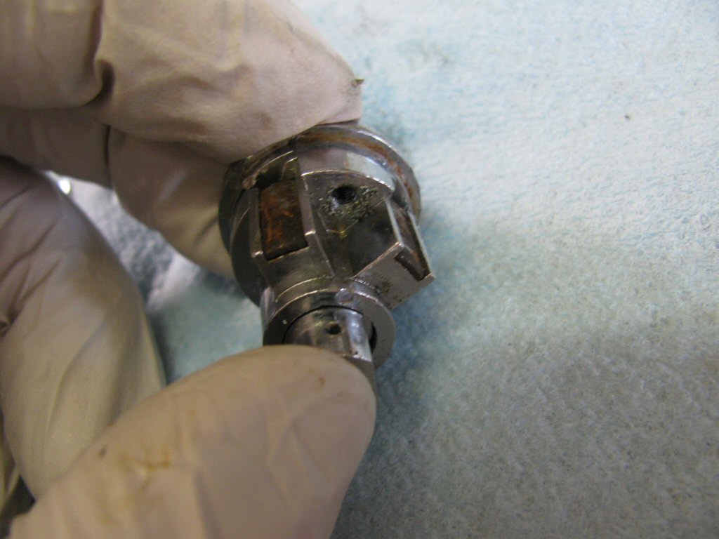
Photo courtesy of Gregory Bender.
- Replace the lever.
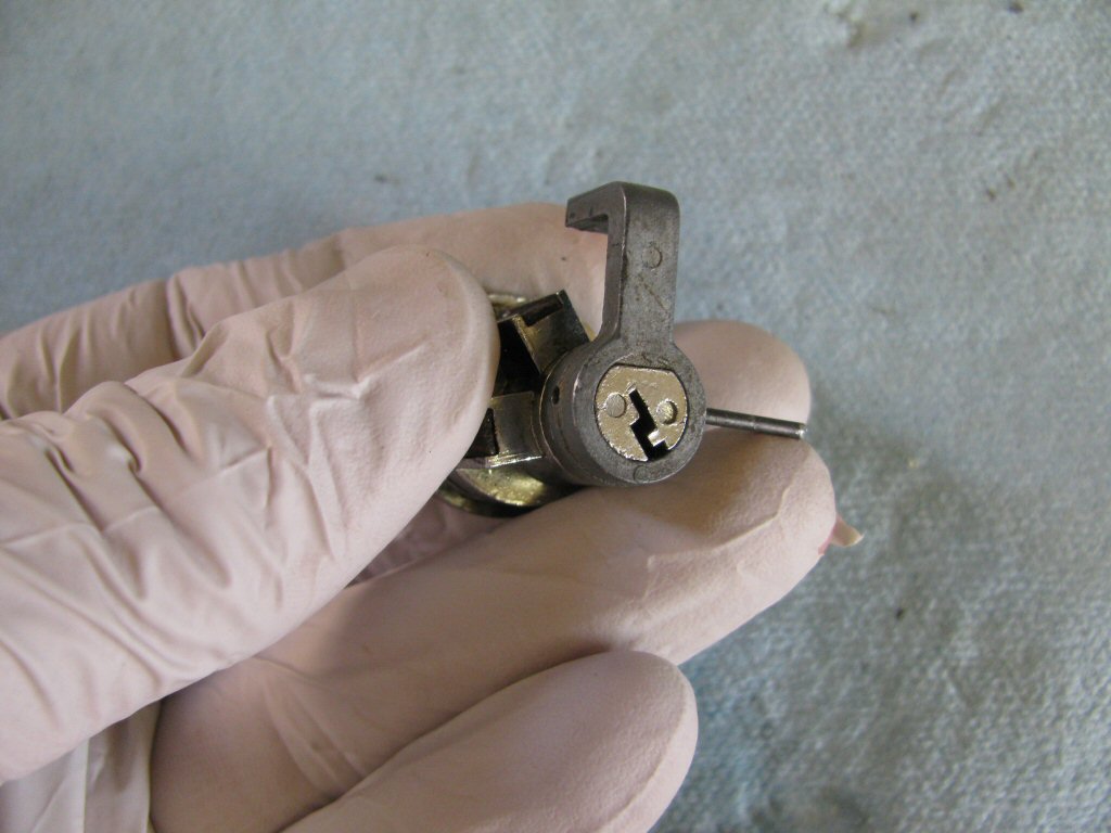
Photo courtesy of Gregory Bender.
- Gently drive the pin back into place.
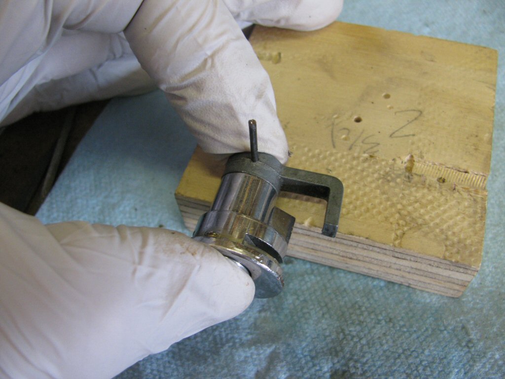
Photo courtesy of Gregory Bender.
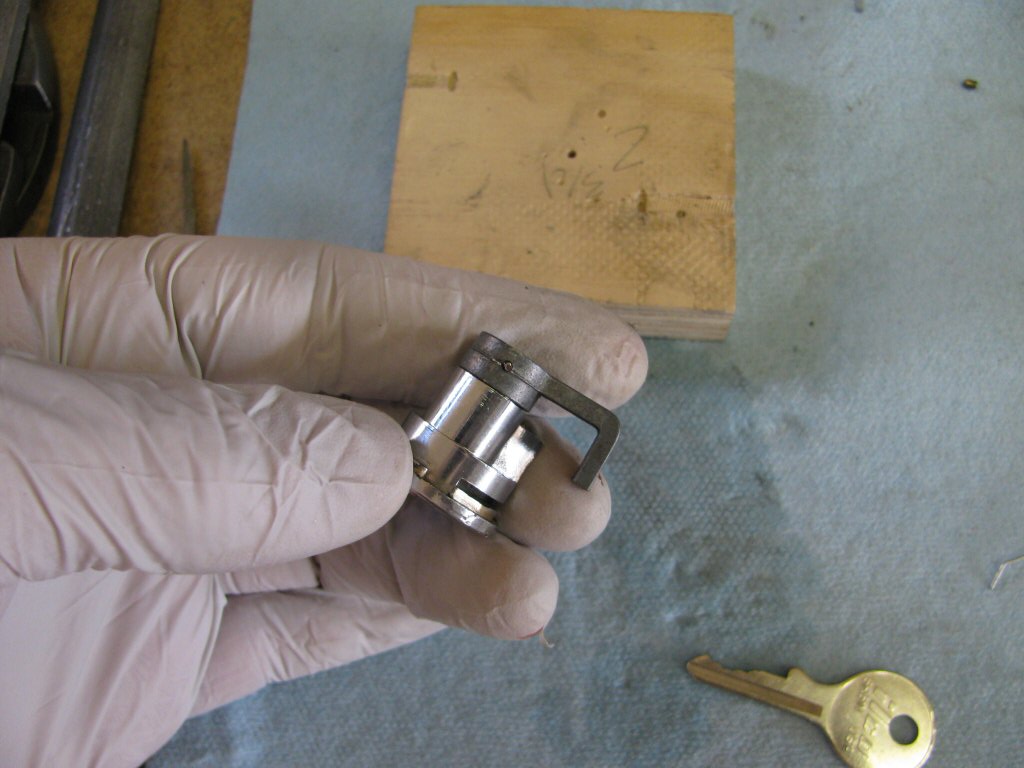
Photo courtesy of Gregory Bender.
- To help prevent things from loosening up due to vibration, I smeared a tiny bit of ThreeBond 1194 sealant on the small metal covers as well as on either end of the lever retaining pin.