Transmission - The loop 4 speed transmission: An exploration
Moto Guzzi V700, V7 Special, Ambassador, 850 GT, 850 GT California, Eldorado, and 850 California Police models
Created:
Updated:
The overview of how the 4 speed transmission functions internally is mine, but I extracted the photos and captions from Rob Prins on the old Yahoo! Loopframe_Guzzi news group (which has now moved to Groups.io). Patrick Hayes later sent me some updated photos showing the proper orientation of the spring loaded shift pawls.
An overview of how the 4 speed transmission functions internally
Basic terminology
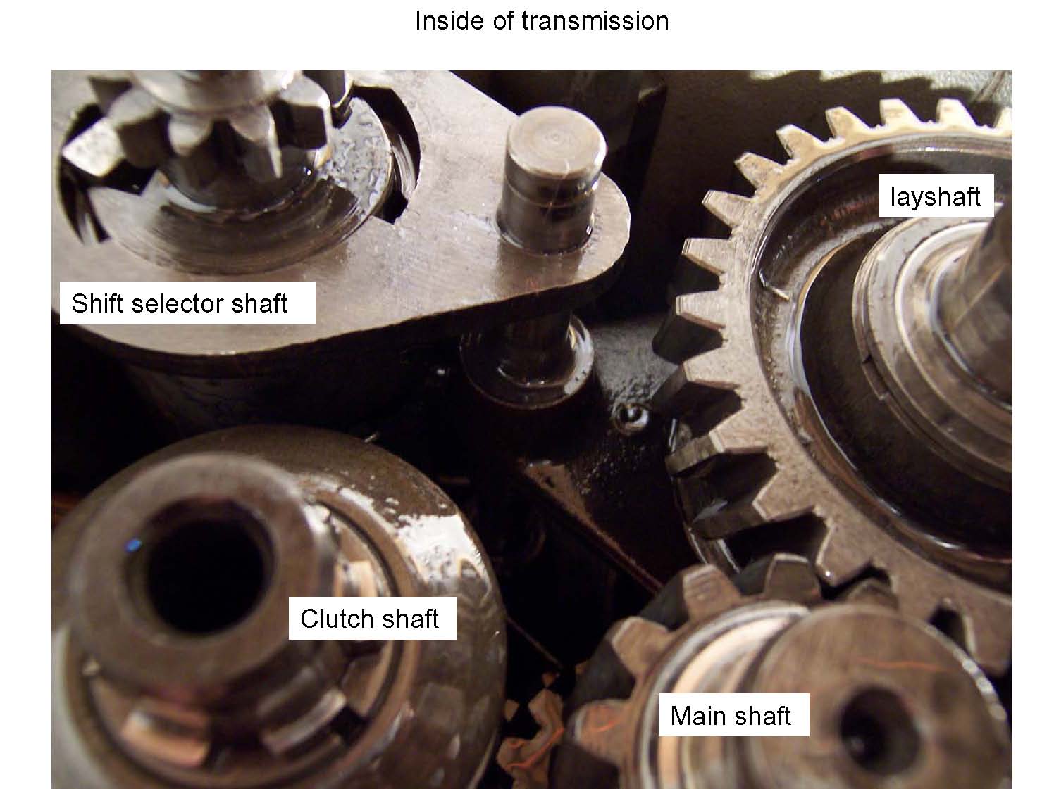
Clutch shaft
Transmission input
Main shaft
Connects the clutch shaft to the lay shaft
Lay shaft
Transmission output
Function
Avoiding the slightly added complexity of 5th gear, here is what is happening with the constantly meshed gears in a 4 speed...
The clutch shaft turns at engine speed at all times (except when the clutch is disengaged, of course) and has one gear. That gear is in constant mesh with the 4th speed gear on the main shaft.
The main shaft has 4 gears (one for each gear available with a 4 speed transmission) and they are fixed to the main shaft. That is, they rotate with the main shaft at all times. Of course, each gear is of a different size because of the need for different gear ratios, etc.
So far, things are very simple: clutch shaft rotates and causes the main shaft to rotate, but all the magic comes in when with the lay shaft.
The lay shaft also has 4 gears and they are always meshed with the 4 gears from the main shaft and they are always being rotated by the main shaft. This is what is meant by a constant mesh gear box - the gears are constantly (always) meshed.
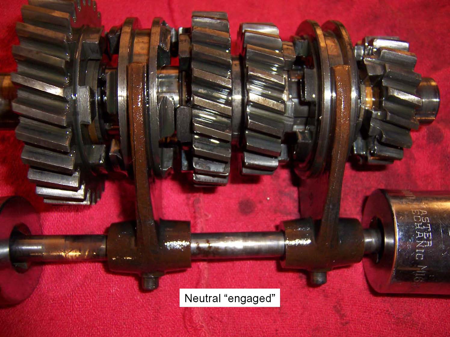
How is it, then, that these gears (of different sizes and ratios) do not bind? Unlike the gear on the clutch shaft and the 4 gears on the main shaft, the gears on the lay shaft are not fixed to the lay shaft. Instead, they rotate on bushings. With all 4 gears on bushings (and the transmission in neutral), the lay shaft rotates independently from the other shafts.
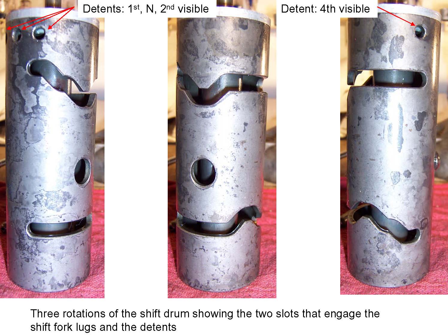
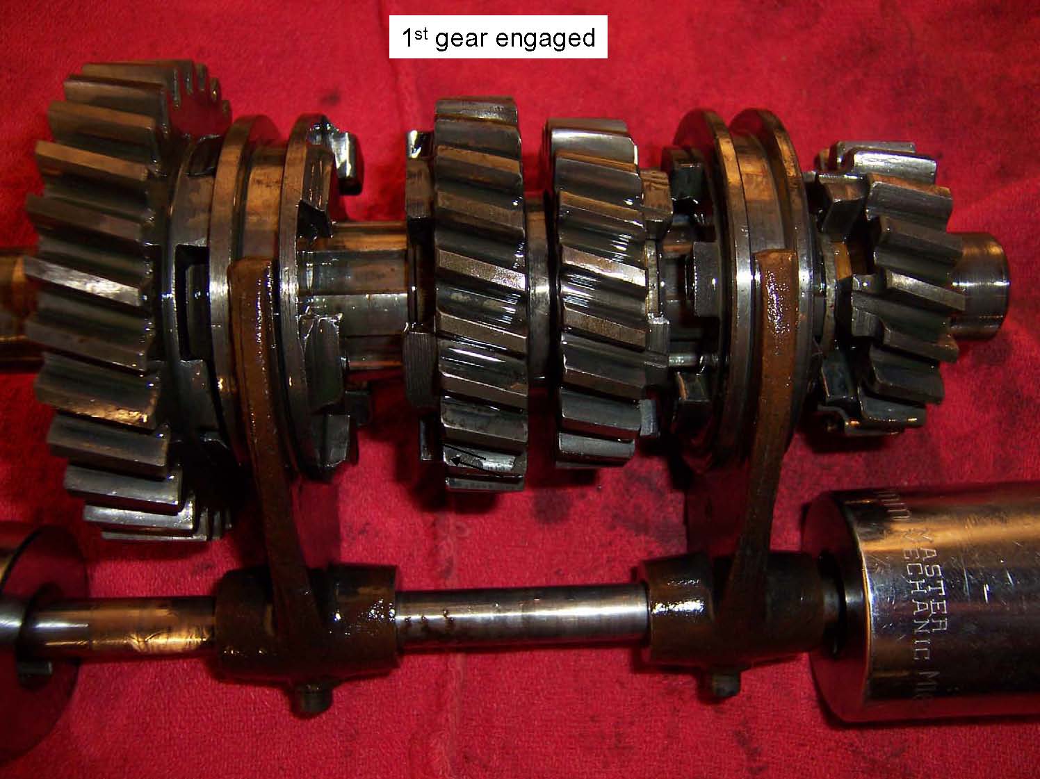
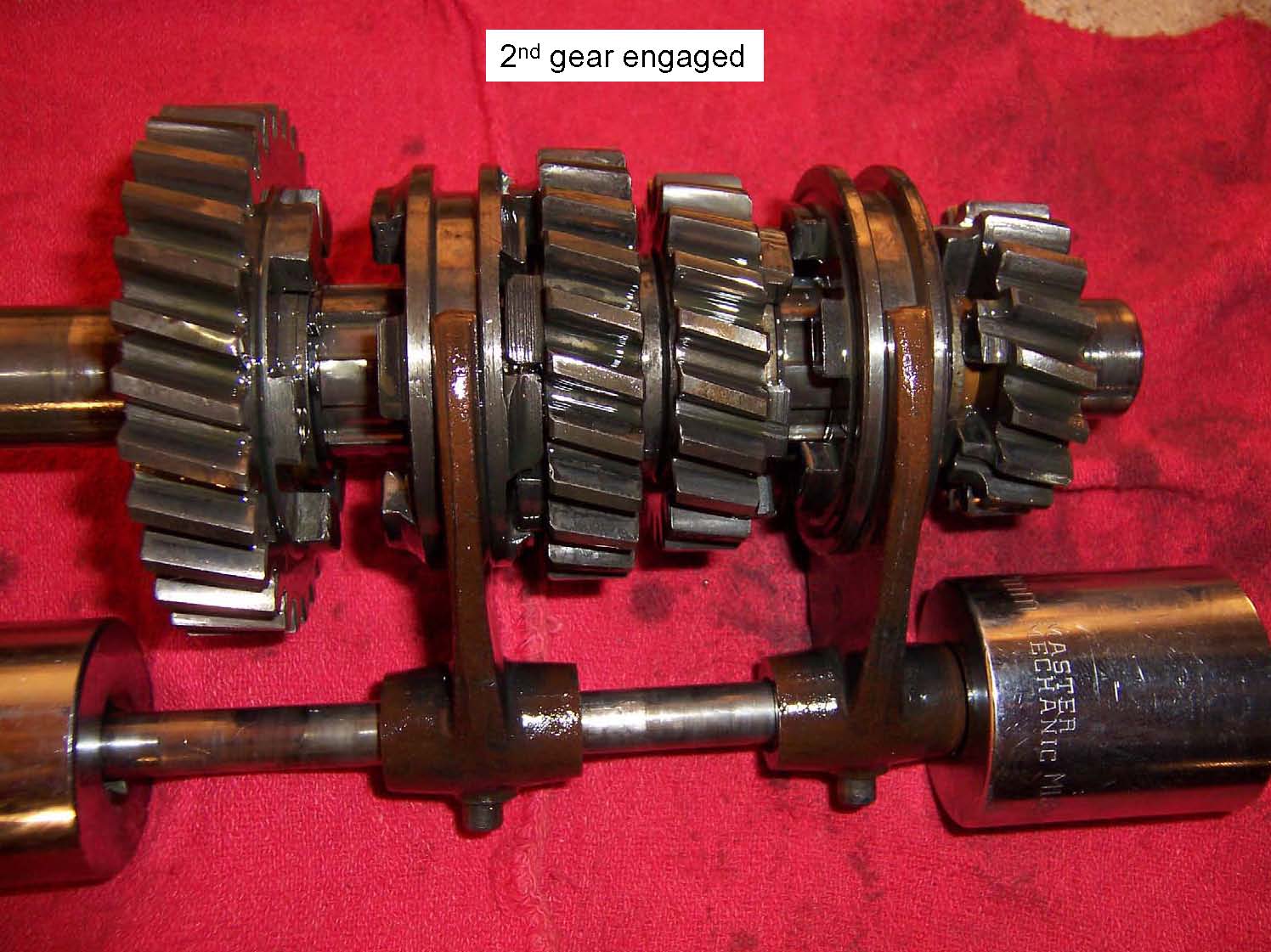
But, in order to transmit rotational power to the rear wheel, we must somehow link one of the freely rotating gears on the lay shaft to the lay shaft. This is done using sliding shift dogs. The 4 speed transmission has 2 shift dogs on the lay shaft: one between first gear and second gear and one between third gear and fourth. The shift dogs can slide easily back and forth along the length of the lay shaft, but, they always rotate with the lay shaft.
Shifting:
N - 1
When you are shifting from neutral into first gear, you are sliding the shift dog located between first gear and second gear so that it interfaces with first gear.
1 - 2
When you are shifting from first gear into second gear, you are sliding the shift dog located between first gear and second gear so that it interfaces with second gear.
2 - 3
When you are shifting from second gear into third gear, you are sliding the shift dog located between first gear and second gear so that it is in between first gear and second gear. At the same time, you are sliding the shift dog located between third gear and fourth gear so that it interfaces with third gear.
3 - 4
Finally, when you are shifting from third gear into fourth gear, you are sliding the shift dog located between third gear and forth gear so that it interfaces with forth gear.
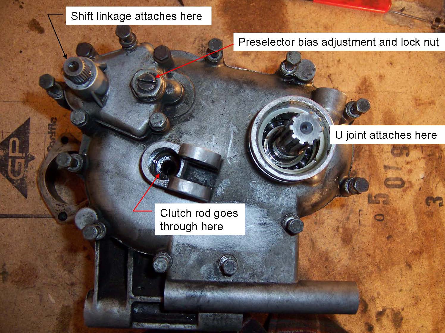
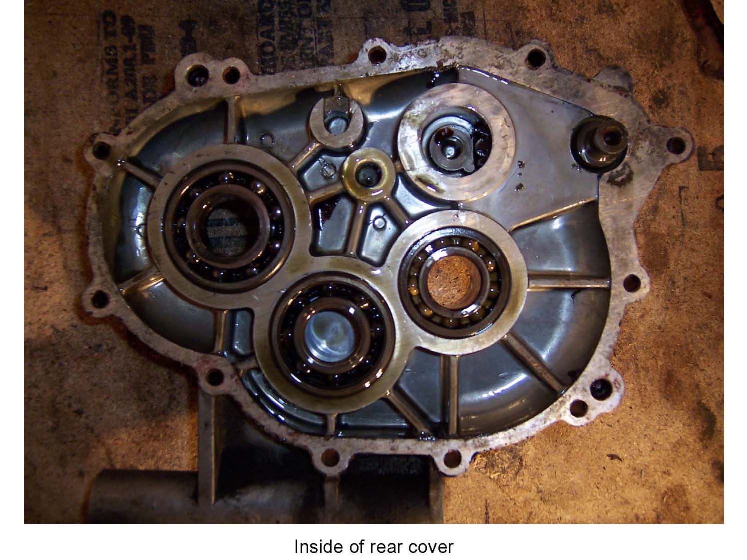
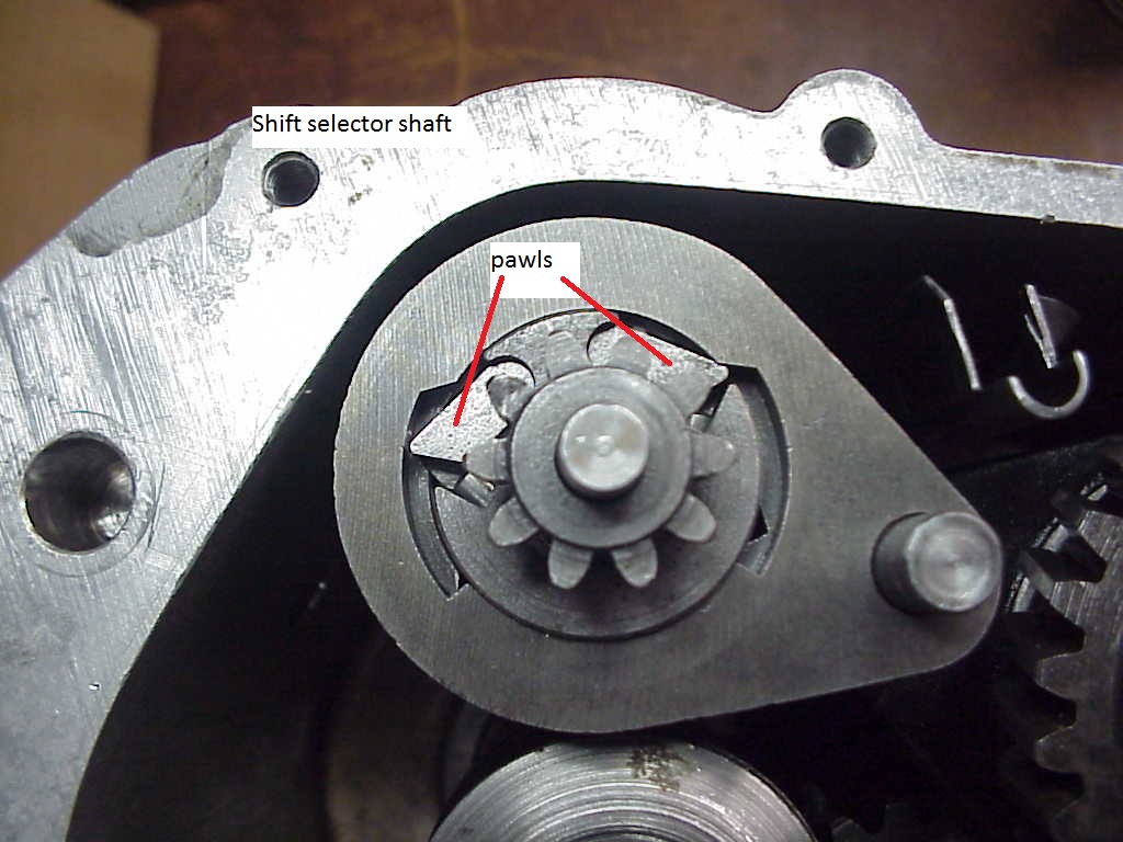
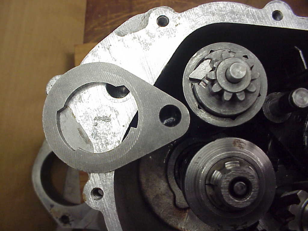
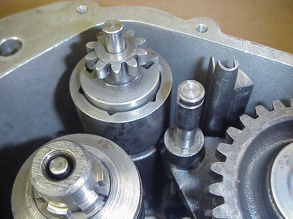
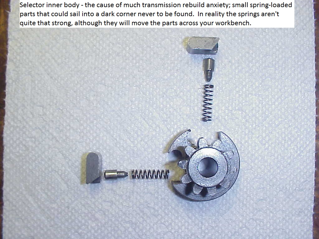
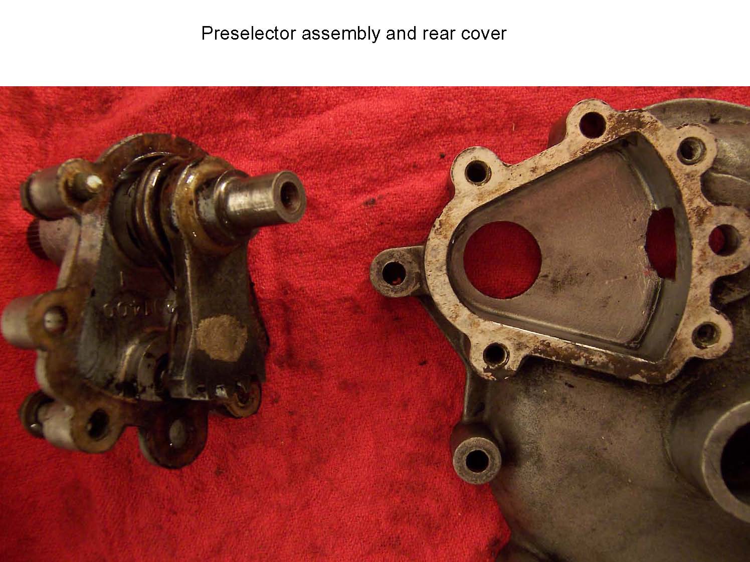
Rob Prins' photos and captions; several updated photos provided by Patrick Hayes.
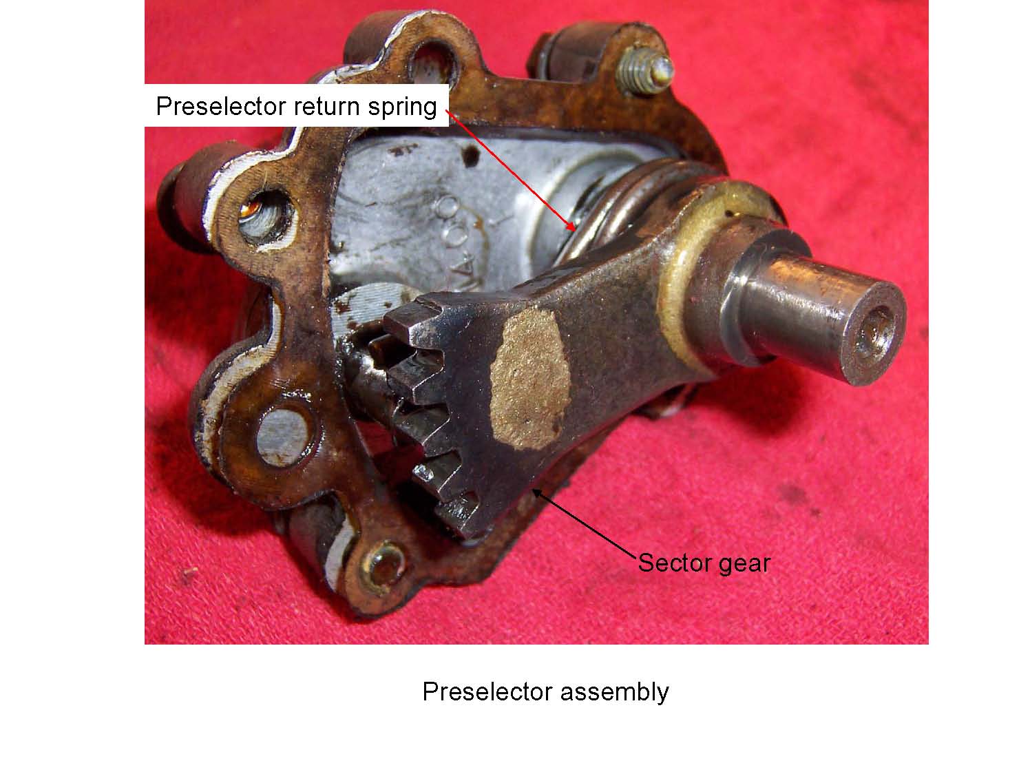
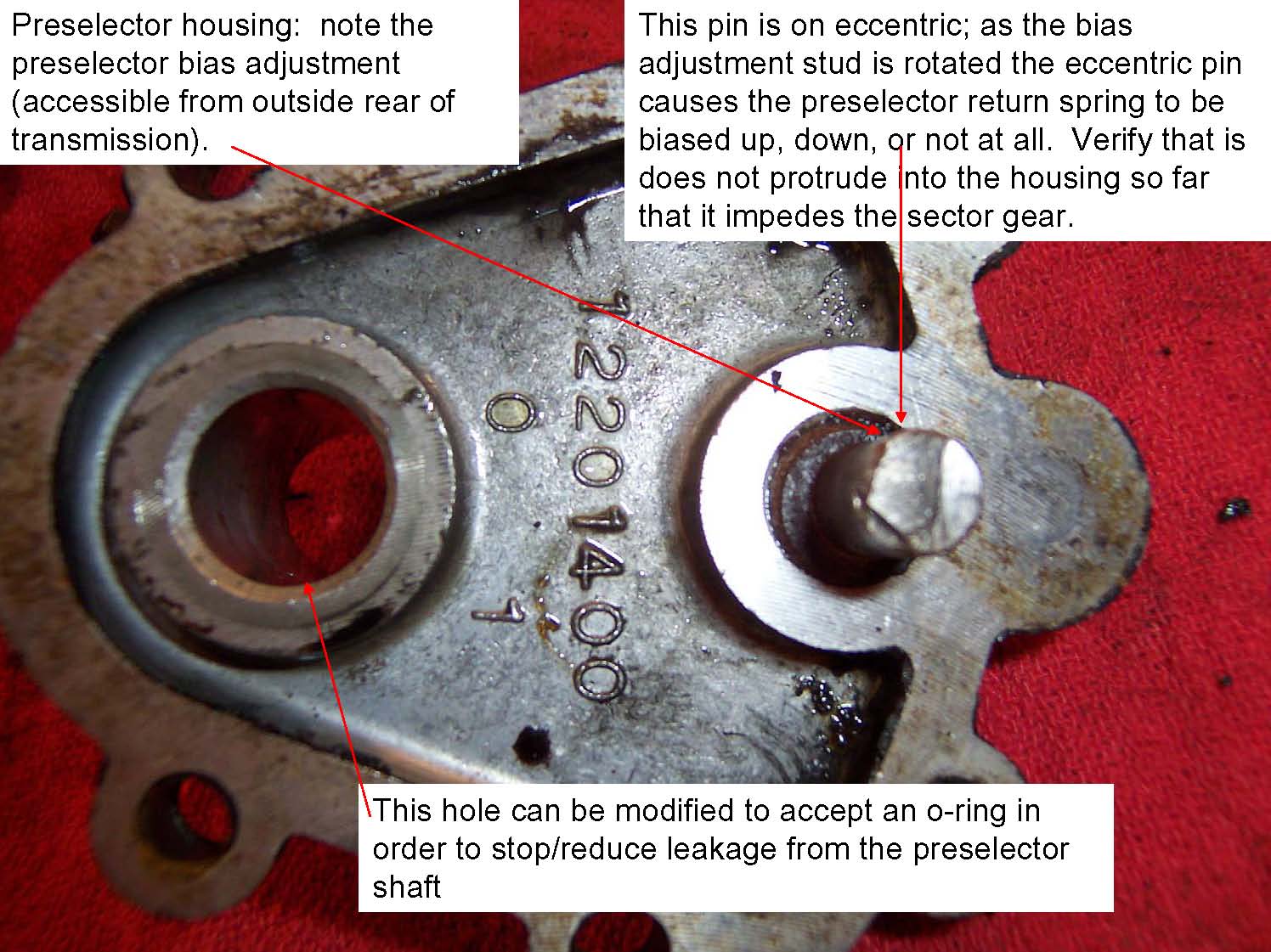
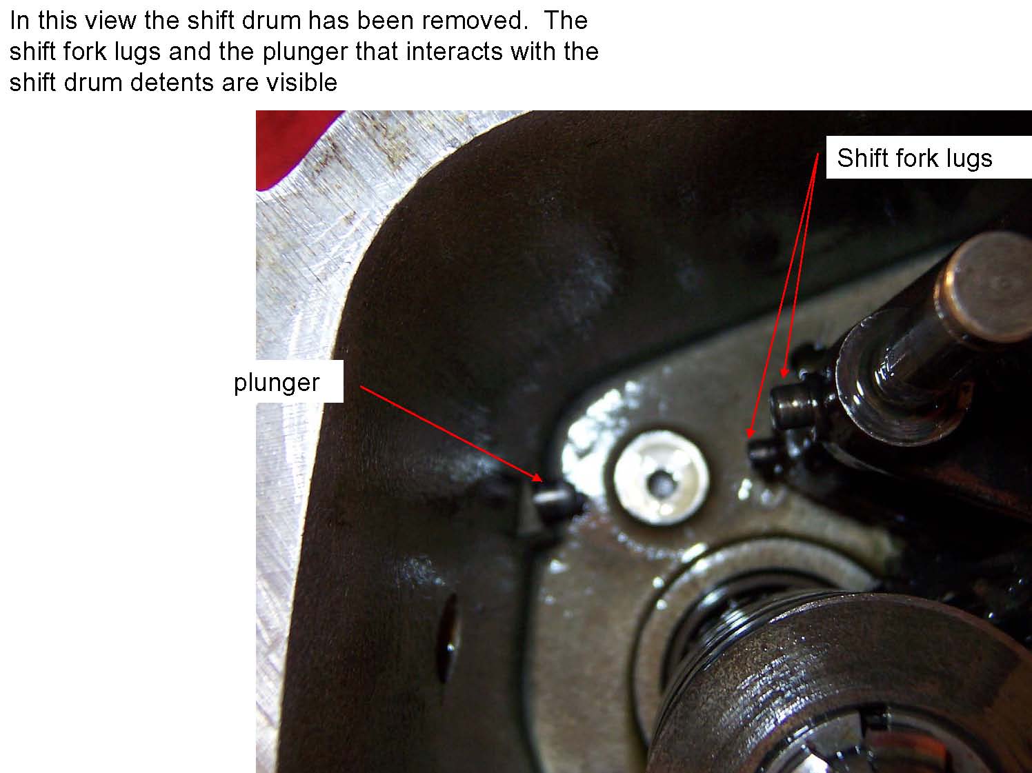
Selector inner body - the cause of much transmission rebuild anxiety; small spring-loaded parts that could sail into a dark corner never to be found. In reality the springs aren't quite that strong, although they will move the parts across your workbench.
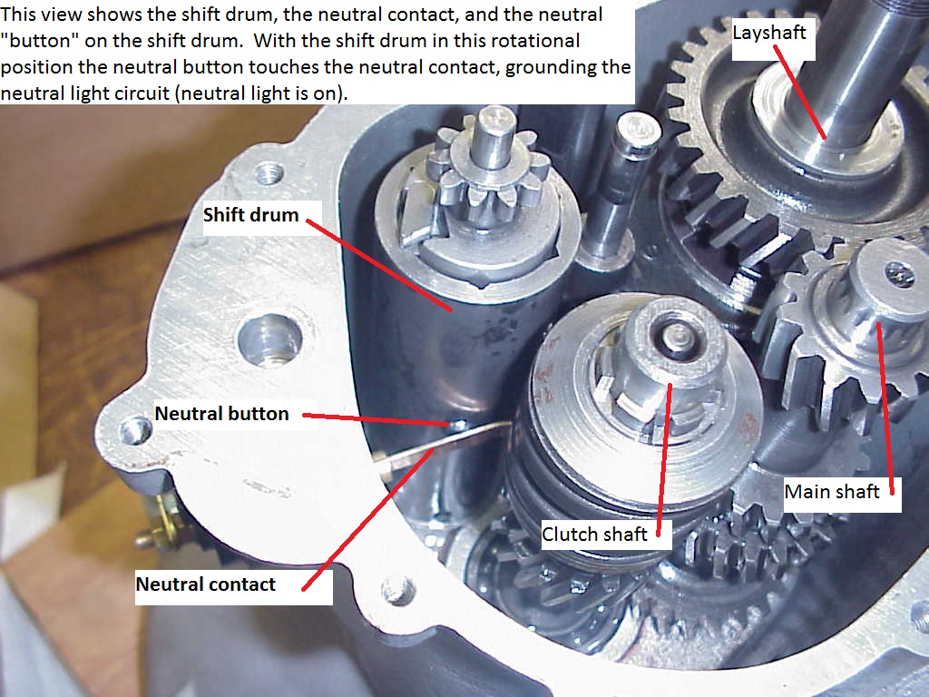
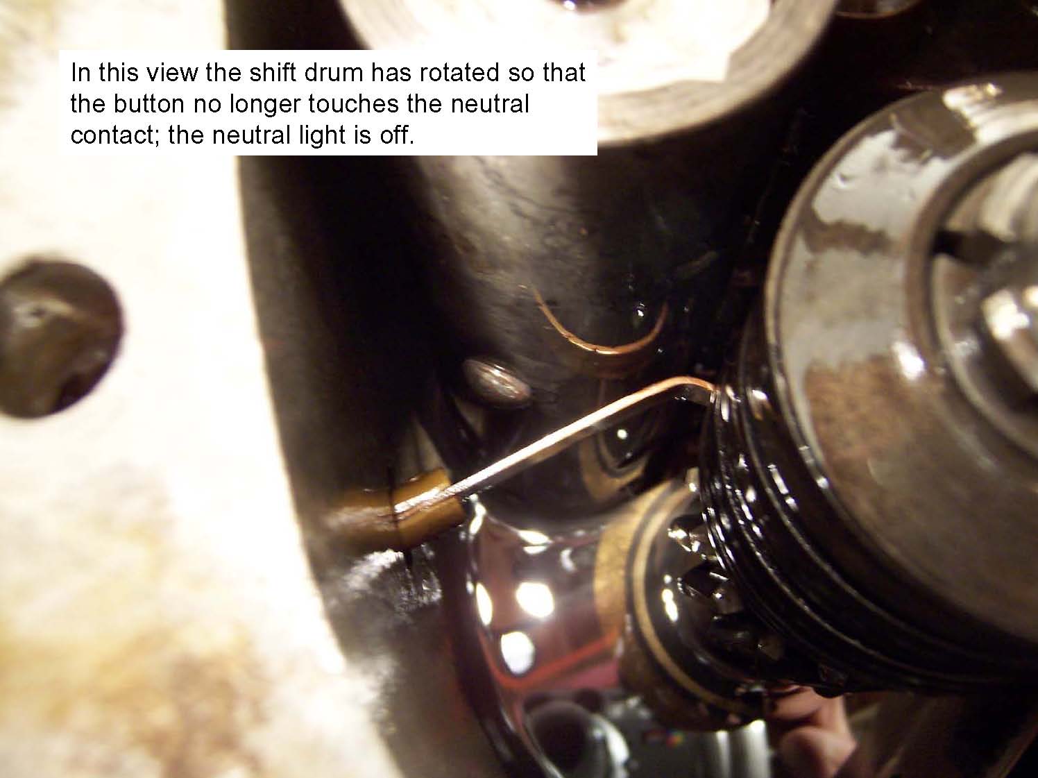
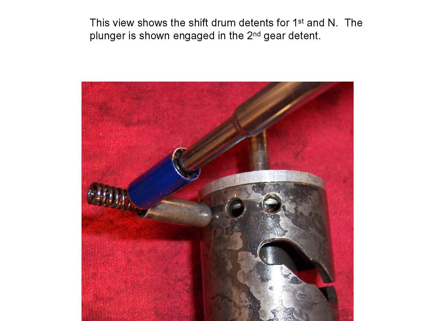
This view shows the shift drum, the neutral contact, and the neutral button on the shift drum. With the shift drum in this rotational position the neutral button touches the neutral contact, grounding the neutral light circuit (neutral light is on).
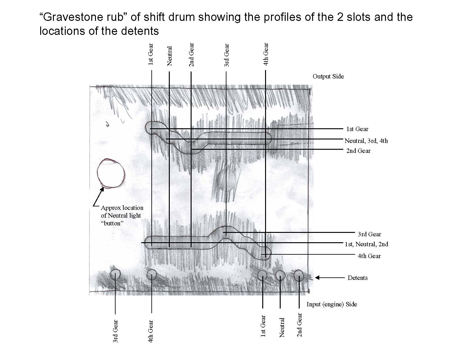
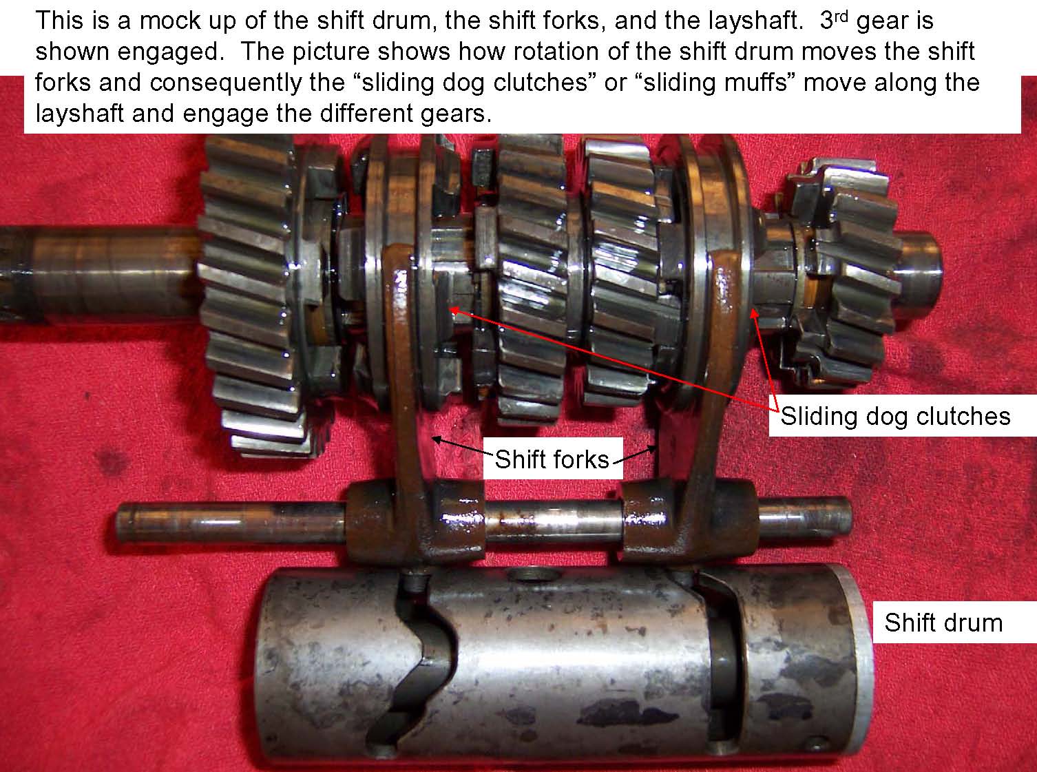
This is a mock up of the shift drum, the shift forks, and the layshaft. 3rd gear is shown engaged. The picture shows how rotation of the shift drum moves the shift forks and consequently the sliding dog clutches or sliding muffs move along the layshaft and engage the different gears.