Toggle switch connections: Dash 4-way flasher switch connections
850 T3 California dash toggle switch electrical connections
The configuration used on the 850 T3 California uses the toggle switch (MG# 13745740) to switch between normal turn signal operation, and rear only flashing lights operation. The dash indicator bulbs function in either position.
Two terminals at one end
- Orange wire
- Orange wire
Two terminals in the middle
- Two wires: both green/black
- Two wires: both pink
Two terminals at the other end
- Yellow/black wire (on same side as green/black wires)
- White/black wire (on same side as pink wires)
V1000 I-Convert dash toggle switch electrical connections
The configuration used on the V1000 I-Convert uses the toggle switch (MG# 13745740) to switch between normal turn signal operation, and rear only flashing lights operation. The dash indicator bulbs function in either position.
Two terminals at one end
- Orange wire
- Orange wire
Two terminals in the middle
- Two wires: both green/black
- Two wires: both pink
Two terminals at the other end
- Yellow/black wire (on same side as green/black wires)
- White/black wire (on same side as pink wires)
V1000 G5 dash toggle switch electrical connections
The configuration used on the V1000 G5 uses the toggle switch (MG# 17745760) to switch between normal turn signal operation, and front & rear flashing lights operation. The dash indicator bulbs function only in the position for normal turn signal operation.
Two terminals at one end
- Orange wire
- Orange wire
Two terminals in the middle
- Two wires: green/black & yellow/black
- Two wires: pink & white/black
Two terminals at the other end
- Green/black wire to the dash indicator light (on same side as green/black wire)
- Pink wire to the dash indicator light (on same side as pink wire)
1000 SP dash toggle switch electrical connections
The configuration used on the 1000 SP uses the toggle switch (MG# 17745760) to switch between normal turn signal operation, and front & rear flashing lights operation. The dash indicator bulbs function in either position.
Two terminals at one end
- Orange wire
- Orange wire
Two terminals in the middle
- Green/black wire
- Pink wire
Two terminals at the other end
- Not used
- Not used
1000 SP II dash toggle switch electrical connections
The configuration used on the 1000 SP II uses the toggle switch (MG# 17745760) to switch between normal turn signal operation, and front & rear flashing lights operation. The dash indicator bulbs function in either position.
Two terminals at one end
- Orange wire
- Orange wire
Two terminals in the middle
- Two wires: both green/black
- Two wires: both pink
Two terminals at the other end
- Not used
- Not used
Le Mans II dash toggle switch electrical connections
The configuration used on the Le Mans II uses the toggle switch (MG# 17745760) to switch between normal turn signal operation, and front & rear flashing lights operation. The dash indicator bulbs function in either position.
Two terminals at one end
- Orange wire
- Orange wire
Two terminals in the middle
- Green/black wire
- Pink wire
Two terminals at the other end
- Not used
- Not used
Le Mans CX 100 dash toggle switch electrical connections
The configuration used on the Le Mans CX 100 uses the toggle switch (MG# 17745760) to switch between normal turn signal operation, and front & rear flashing lights operation. The dash indicator bulbs function in either position.
Two terminals at one end
- Orange wire
- Orange wire
Two terminals in the middle
- Green/black wire
- Pink wire
Two terminals at the other end
- Not used
- Not used
Le Mans III dash toggle switch electrical connections
The configuration used on the Le Mans III uses the toggle switch (MG# 17745760) to switch between normal turn signal operation, and front & rear flashing lights operation. The dash indicator bulbs function in either position.
Two terminals at one end
- Orange wire
- Orange wire
Two terminals in the middle
- Green/black wire
- Pink wire
Two terminals at the other end
- Not used
- Not used
Le Mans 1000 dash toggle switch electrical connections
The configuration used on the Le Mans 1000 uses the toggle switch (MG# 28745760 or MG# 28745761) to switch between normal turn signal operation, and front & rear flashing lights operation. The dash indicator bulbs function in either position.
Earlier MG# 28745760 switch
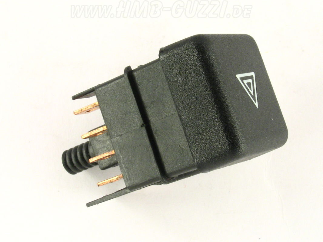
Photo courtesy of HMB-Moto.
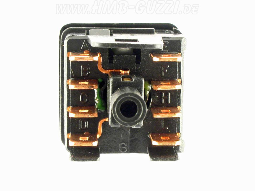
Photo courtesy of HMB-Moto.
- A - Yellow wire
- B - White/blue wire
- C - unknown (could be White/blue or Orange)
- D - Black
- E - Pink
- F - unknown (could be White/blue or Orange)
- G - Not used
- H - Green/black
- L - Not used
Later MG# 28745761 switch
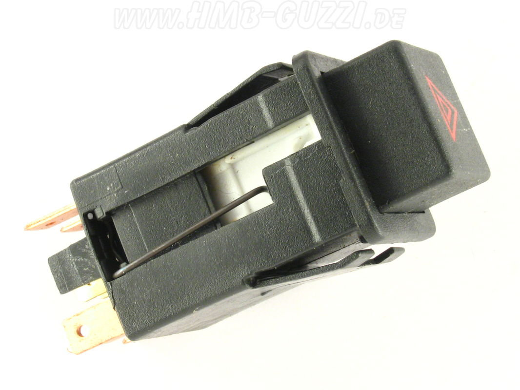
Photo courtesy of HMB-Moto.
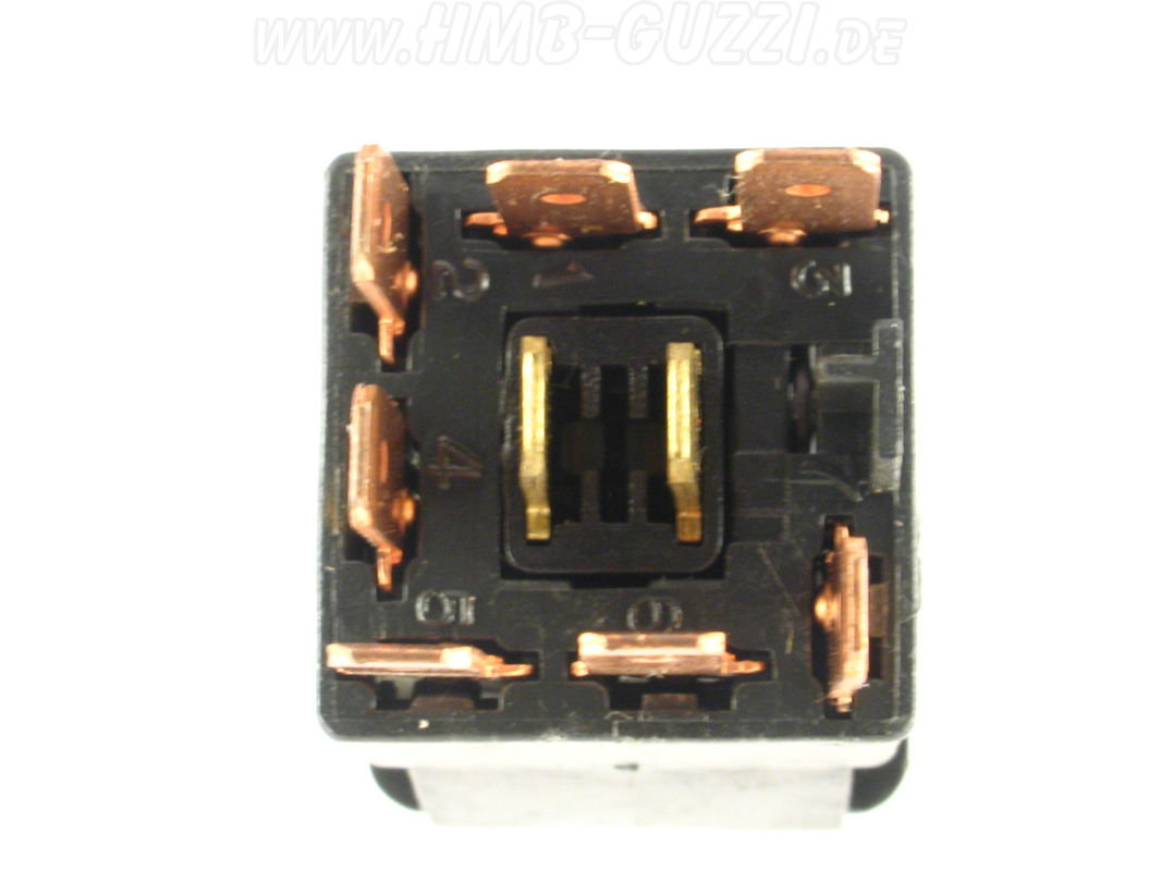
Photo courtesy of HMB-Moto.
- 1 - White/blue
- 2 - Empty
- 3 - White/blue
- 4 - Orange
- 5 - Green/black
- 6 - Pink
- One of the unlabeled terminals in the middle of the switch will receive a black wire
- The other unlabeled terminal in the middle will receive a short white/blue wire that connects directly to the unlabeled terminal in the opposite corner of terminal 2
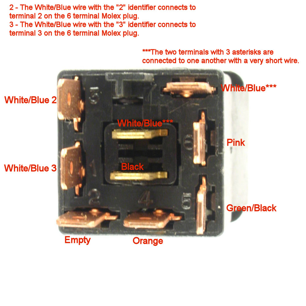
Photo courtesy of Gregory Bender.
California II dash toggle switch electrical connections
The configuration used on the California II uses the toggle switch (MG# 17745760) to switch between normal turn signal operation, and front & rear flashing lights operation. The dash indicator bulbs function in either position.
Two terminals at one end
- Orange wire
- Orange wire
Two terminals in the middle
- Green/black wire
- Pink wire
Two terminals at the other end
- Not used
- Not used
California III dash toggle switch electrical connections
The configuration used on the California III uses the toggle switch (MG# 28745760 or MG# 28745761) to switch between normal turn signal operation, and front & rear flashing lights operation. The dash indicator bulbs function in either position.
Earlier MG# 28745760 switch
Photo courtesy of HMB-Moto.
Photo courtesy of HMB-Moto.
- A - Yellow wire
- B - White/blue wire
- C - unknown (could be White/blue or Orange)
- D - Black
- E - Pink
- F - unknown (could be White/blue or Orange)
- G - Not used
- H - Green/black
- L - Not used
Later MG# 28745761 switch
Photo courtesy of HMB-Moto.
Photo courtesy of HMB-Moto.
- 1 - White/blue
- 2 - Empty
- 3 - White/blue
- 4 - Orange
- 5 - Green/black
- 6 - Pink
- One of the unlabeled terminals in the middle of the switch will receive a black wire
- The other unlabeled terminal in the middle will receive a short white/blue wire that connects directly to the unlabeled terminal in the opposite corner of terminal 2
Photo courtesy of Gregory Bender.