Timing belt and pulley replacement instructions / how to / DIY
DIY and how-to
articles on repairing the Saab 9-5 SE.
Disclaimer: We own a 2000 Saab 9-5 SE 6 cylinder 4-door sedan. This information may not be at all applicable to other Saab 9-5 models.
With 120,000 miles on the odometer, our Saab was ready for it's timing belt to be replaced. I knew that I also wanted to change out the tensioning and idler pulleys at the same time. But, having never changed a timing belt before, I was more than a little apprehensive about doing this work myself.
I called a couple of experienced and trustworthy independent shops in the Phoenix area to see what it would cost if I had someone else perform the work. USD $1,200.00 and maybe more got me thinking more about doing this work myself. So, I started doing some research to see what all was involved with this job.
At some point along the way, I figured I could perform this work myself. So I started reading more, ordering tools and parts. In the end, it all worked out perfectly and I'm quite pleased that I did the job myself. Not only did I save more than a little money, but now I have the knowledge I can use again in the future.
Special tools
- One of the first things I realized I would need is a specialized set of timing belt tools. Certainly I could have cobbled together a set of homemade tools that would have gotten the job done. But, I really didn't want to take any chances. I thought about renting tools. But, when I found the complete set of specialized tools (OTC Part Number 6687) from Network Tool Warehouse, I jumped on it. This set worked very well for me.
- A set of internal star bits are needed (Harbor Freight item number 67914 or Harbor Freight item number 67887 or Harbor Freight item number 67886).
- A set of external star bits are needed (Harbor Freight item number 67930).
- The remaining tools primarily consisted of wrenches, sockets, and the like.
Parts
Next up for purchase were the parts. Although I knew the belt had to be replaced, I also wanted to swap out the one tensioner and two idler pulleys. A kit from Rock Auto (Gates TCK285) for USD $129.99 included the belt, tensioner pulley, both idler pulleys, and a new backing plate for the tensioner pulley and upper idler pulley. I knew from reading online that the backing plate would *not* fit my engine. But, removing the pulleys from the new backing plate and fitting them to the original backing plate took no time at all. The cost savings of reusing the original backing plate (which isn't a wear item) was significant (around USD $250.00). I would definitely go this way again.
Strictly speaking, that is all I needed to change. But, since I was into the engine that far anyway, I decided to replace the water pump (USD $61.99 from my local auto parts store) and serpentine belt (USD $29.90 from eEuroparts). I'm glad I did.
Source of information
I read many different bits of information (multiple times each) before I began this work. The instructions below are a compilation of my experience and the information from the following sources:
- Chris from CT's (WhiteTurbo) post on Saab Central
- David Ingram's post on The Saab Network
- Anders' (SWEDECAR) post on The Saab Network
- Saab Workshop Information System (WIS)
- Instructions that came with the Gates kit
- Instructions that came with the OTC special tools.
Instructions
Part 1: Accessing the timing belt and pulleys
- Set the parking brake and open the hood.
- Jack up the car using the right side rear jack point. Raise the car high enough from that point and you will be able to remove the front wheel. I used this rear jack point so that I could shove a jack stand under the right side front jack point. With the jack stand in place, lower the jack.
- Remove the right front tire.
- Remove both of plastic shrouds from underneath the engine as well as the plastic shroud that fits inside the right front wheel well.
- Place a jack underneath the oil pan. Place a piece of wood between the jack and the oil pan to disperse the pressure on the pan. Raise the jack so that the pressure is taken off the right side motor mount. You won't need to raise it much, just enough.
- Optional: If you are going to replace the water pump, now is a perfect time to start draining the coolant.
- Disconnect the negative battery terminal.
- Remove the black plastic cover that hides the engine.
- Remove both Direct Ignition Cassettes.
- Remove all spark plugs.
- Set the Direct Ignition Cassettes back in place to prevent anything from falling into the open spark plug holes.
- Loosen the hose clamps on the Air Mass Meter, disconnect the electrical connection, and set the air mass meter aside (some place safe).
- Remove the three vertical bolts that secure the top of the engine mount bracket to the engine mount. If it seems that there is any pressure on the bolts as you remove them, raise the jack under the oil pan to relieve the pressure.
- Remove the engine mount from the engine block.
- Loosen (but do not remove) the bolts securing the pulley to the water pump.
- Loosen (but do not remove) the bolts securing the pulley to the steering pump.
- Loosen (but do not remove) the bolts securing the pulley to the crankshaft.
- If you are going to reuse the serpentine belt, mark it for the direction of rotation so you can install it back in the same direction (masking tape and a pen works well).
- If you do not have the Saab WIS showing how the serpentine belt is routed, draw a picture of the routing.
- Remove the serpentine belt by placing a wrench on the bolt that secures the tensioner pulley to the tensioner. Rotate the wrench clockwise to relieve the pressure on the belt.
- Remove the pulley to the water pump.
- Remove the pulley to the steering pump.
- Remove the pulley to the crankshaft.
Note: I marked the crankshaft pulley to indicate the position of one bolt so I would be certain to reinstall it in the same position. When I went to reinstall the pulley, I discovered that the holes in the pulley are not symmetrically drilled...allowing for fitment in only one location. Thus, I didn't need to mark the pulley. - Remove the black plastic cool-air duct that is connected to the alternator. This is a friction fit and just pulls off.
- Remove the complete serpentine belt tensioner. It is secured by two bolts that require a 16 mm socket (a wrench will not fit).
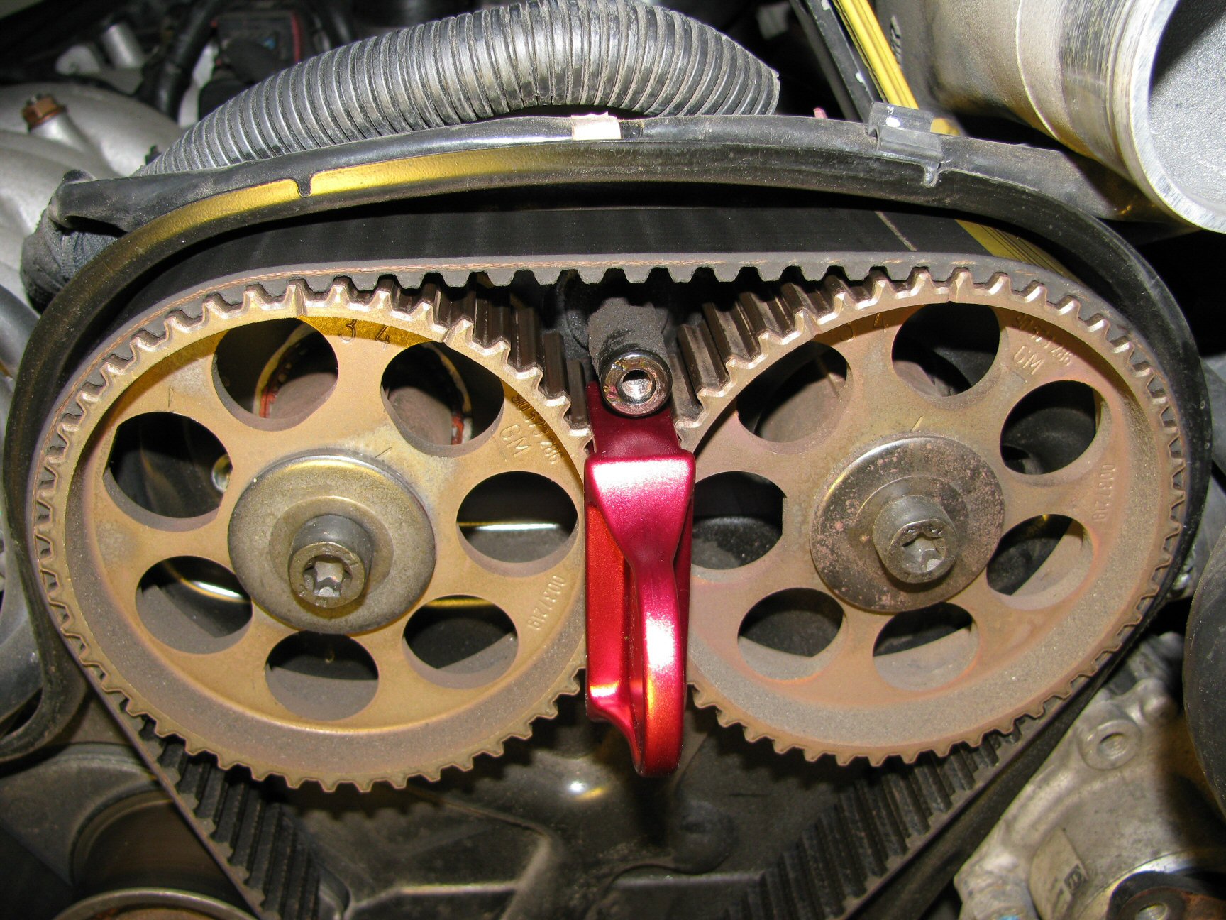
- Remove the black plastic timing belt cover. The timing belt and pulleys will now be exposed.
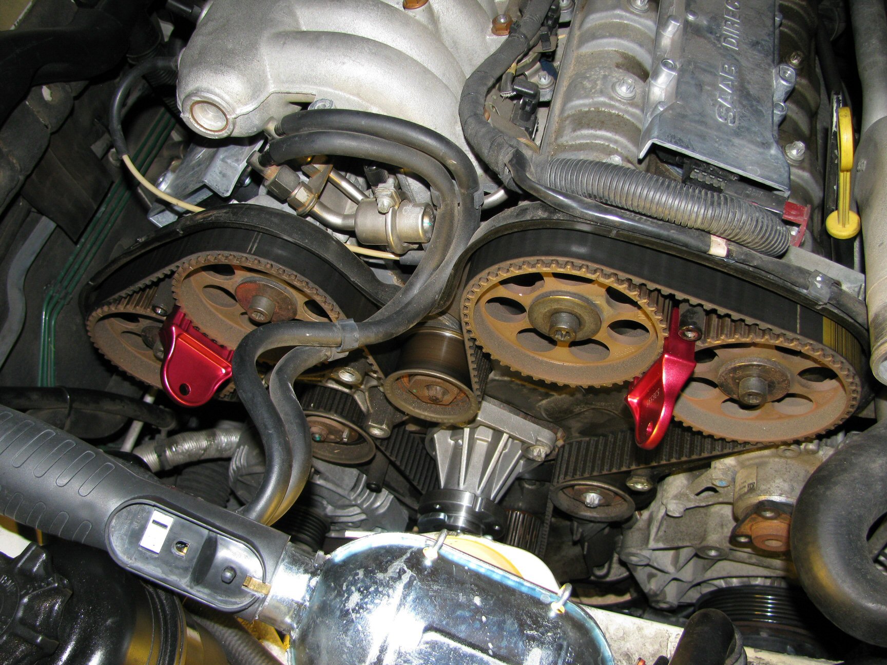
Timing belt and pulleys exposed. Camshaft pulleys 1 (left) through 4 (right). Photo courtesy of Gregory Bender.
- Optional: If you are going to replace the water pump, now is a great time to remove it, clean up the mating surface on the engine block, and fit the new water pump.
Part 2: Changing the timing belt and pulleys
- Rotation of the engine is clockwise. As you would expect, this is clockwise as you are facing the timing belt. Never rotate the engine counter-clockwise. If you go past where you want to be, rotate the engine clockwise the required number of revolutions to get back to where you need to be. Do not
back up
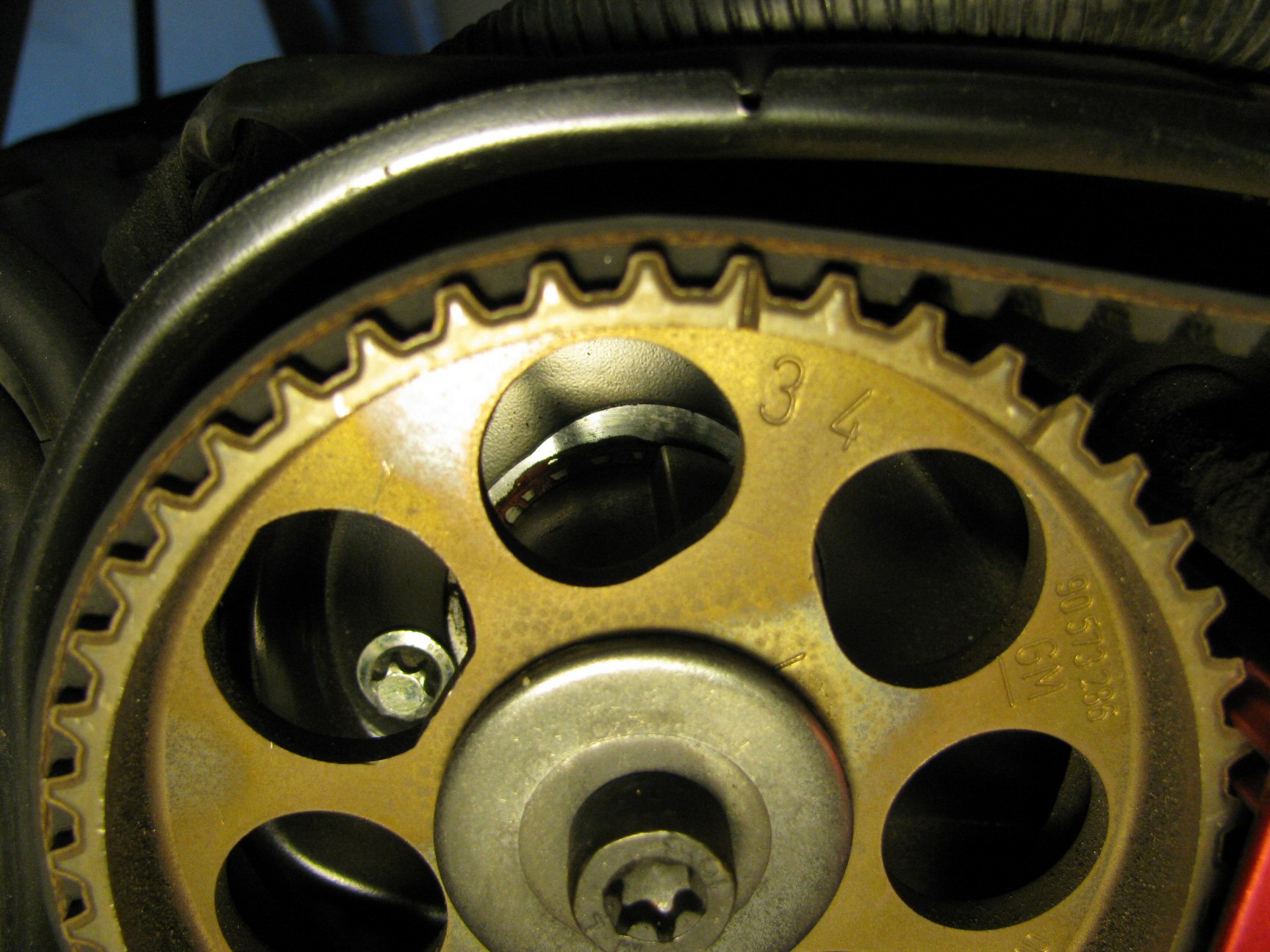
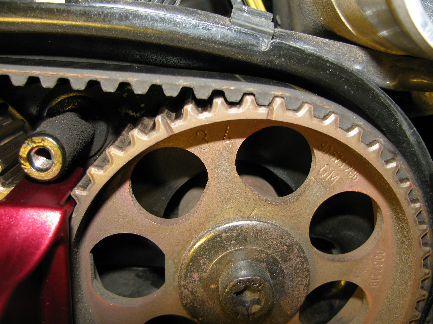
. - Rotate the crankshaft and bring the engine to Top Dead Center (TDC). The notch in the hub for the crankshaft pulley will be pointing straight down in alignment with the corresponding notch on the engine block. The marks on the camshaft pulleys should align with the corresponding notches in the backing tin that surrounds the timing belt. If the notches in the camshaft pulleys do not align properly, rotate the crankshaft one more revolution and the notches should be in alignment.
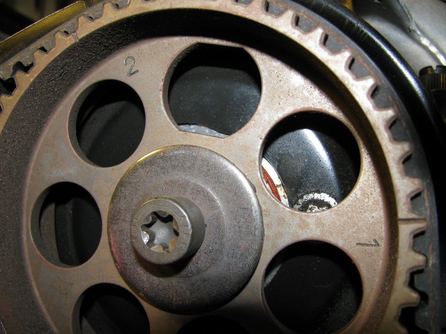
Note: Camshafts 1 and 2 use an identical pulley with identical notches and markings. Likewise, camshafts 3 and 4 use an identical pulley with identical notches and markings. Each camshaft pulley will have two notches and a stamp next to each notch:1
or2
on the left two camshaft pulleys;3
or4
on the right two camshaft pulleys. The number closest to the notch should be the notch that is aligned with the notches in the backing tin that surrounds the timing belt. Don't get confused about this. Just bring the crank to top dead center and make sure the notches are in alignment. If nothing aligns, rotate the crank 360° and now the notches should be in alignment. See the photos below.
Note: Do not expect the lines on the belt to align with the notches in the camshaft. I suppose they might, but that would be very rare.
Note: I spent considerable time rotating the crankshaft and observing how the notches came into alignment. I didn't need to do this, but I wanted to be absolutely certain that I understood how things were intended to be aligned before I took anything apart. You may wish to do the same.
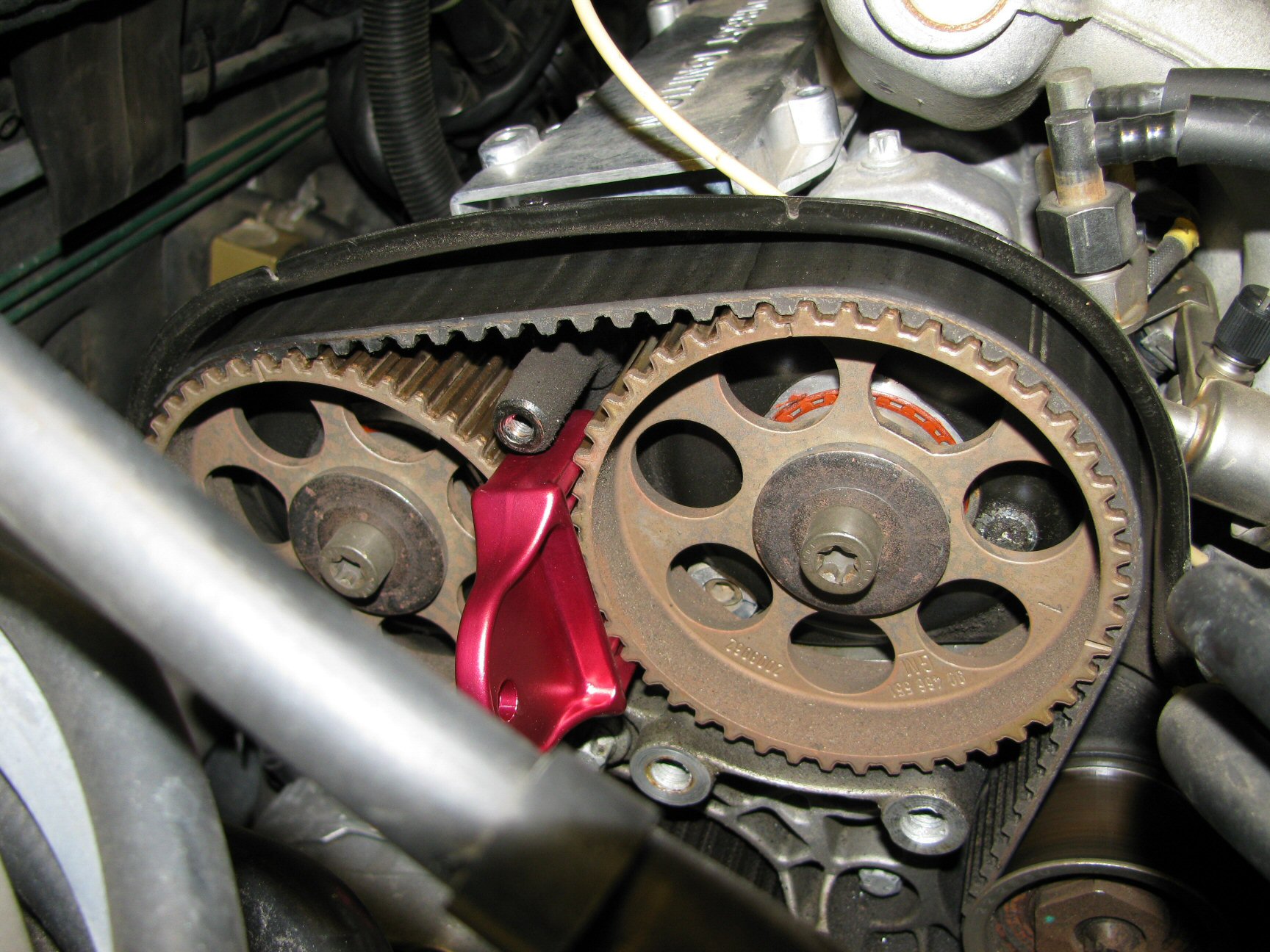
Camshaft pulleys 1 (left) and 2 (right). Photo courtesy of Gregory Bender.
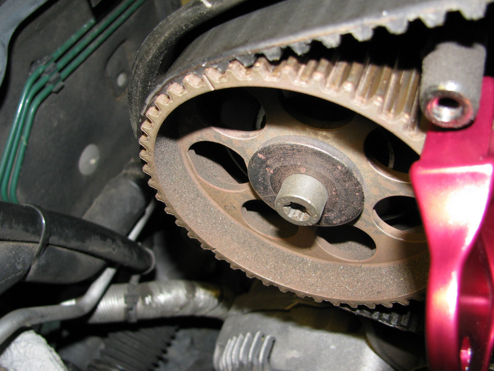
Camshaft pulley 1 aligned with notch in backing tin. Photo courtesy of Gregory Bender.
Camshaft pulley 2 aligned with notch in backing tin. Photo courtesy of Gregory Bender.
Camshaft pulleys 3 (left) and 4 (right). Photo courtesy of Gregory Bender.
Camshaft pulley 3 aligned with notch in backing tin. Photo courtesy of Gregory Bender.
Camshaft pulley 4 aligned with notch in backing tin. Photo courtesy of Gregory Bender.
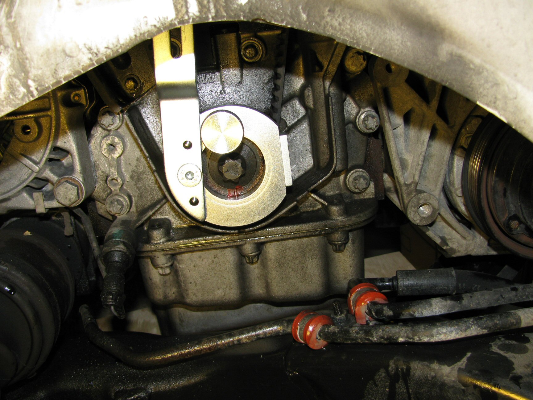
Notch on crankshaft pulley hub aligned with notch on engine block. Photo courtesy of Gregory Bender.
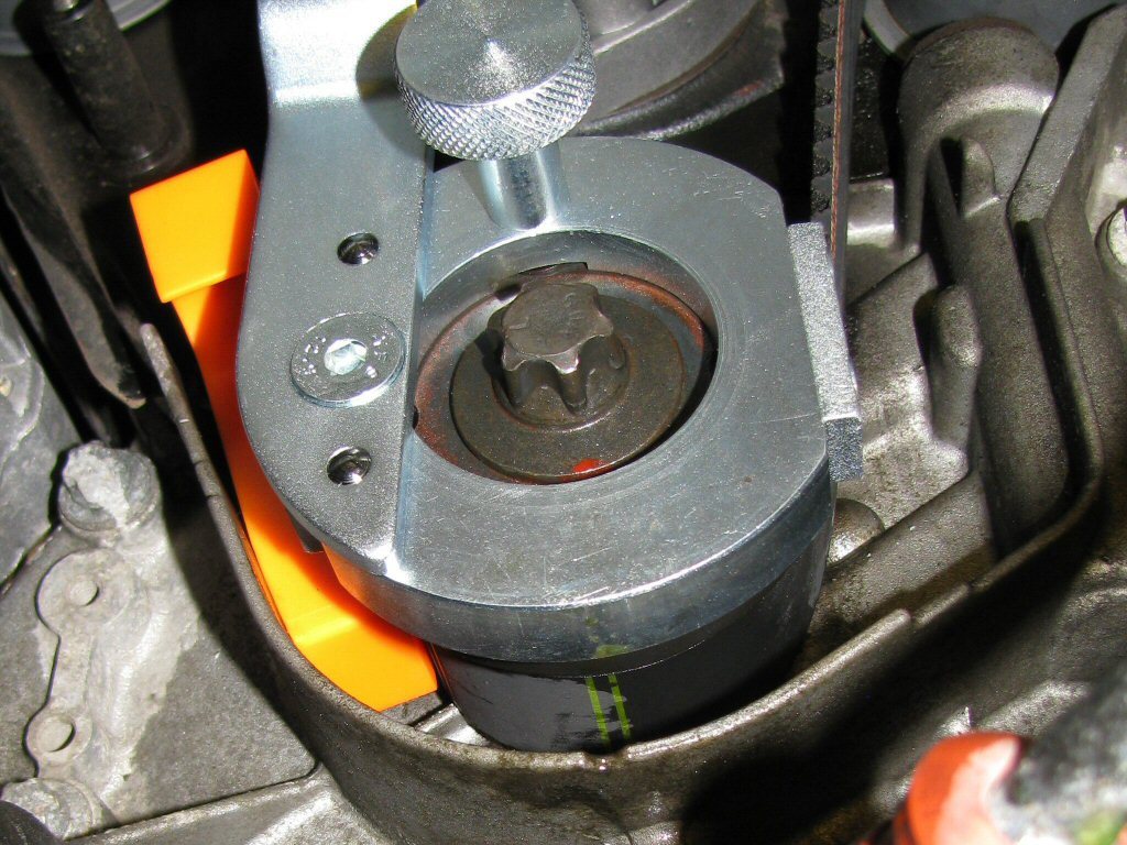
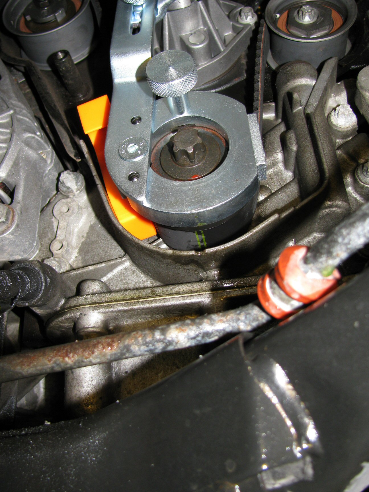
- Once you are certain you understand how everything functions, rotate the crankshaft almost two complete revolutions. Just before the crankshaft is at TDC, fit the crankshaft locking tool and then rotate the crankshaft the rest of the way to TDC and lock the tool to the water pump. The crankshaft locking tool is very nice because you do not need to visually align the crankshaft using the notches. Instead, the locking tool will come to rest against the water pump and the crankshaft will be at TDC. Done. It couldn't be easier.
- Fit the camshaft pulley locks to both sets of cam pulleys. If they don't fit easily, don't force them. You may need to remove the crankshaft locking tool and rotate the crankshaft around almost two complete revolutions again. Refit the crankshaft locking tool and then slowly rotate the crankshaft while you insert the camshaft pulley locks.
- Before proceeding, verify the following:
- Crankshaft is at TDC, notch pointing straight down.
- Crankshaft is locked with the special locking tool.
- The notches on the pulleys for camshafts 1 and 2 are properly aligned with the notches in the backing tin.
- The pulleys on camshafts 1 and 2 are held in place with the special locking tool.
- The notches on the pulleys for camshafts 3 and 4 are properly aligned with the notches in the backing tin.
- The pulleys on camshafts 3 and 4 are held in place with the special locking tool.
- Optional: I took the time to mark on my old belt where the notches in the crankshaft and camshaft pulleys where located. I did this so that I would 100% sure of which lines to use on my new belt. While you shouldn't need to do this, it doesn't take long and then you will be sure that your belt is correct for your application. This also allowed me to verify that I should use the green lines for the crankshaft and camshaft pulleys 1 and 2; and use the white lines for camshaft pulleys 3 and 4.
- Remove the nut securing the tensioning pulley in place. Remove the pulley and take note of any spacers behind the pulley.
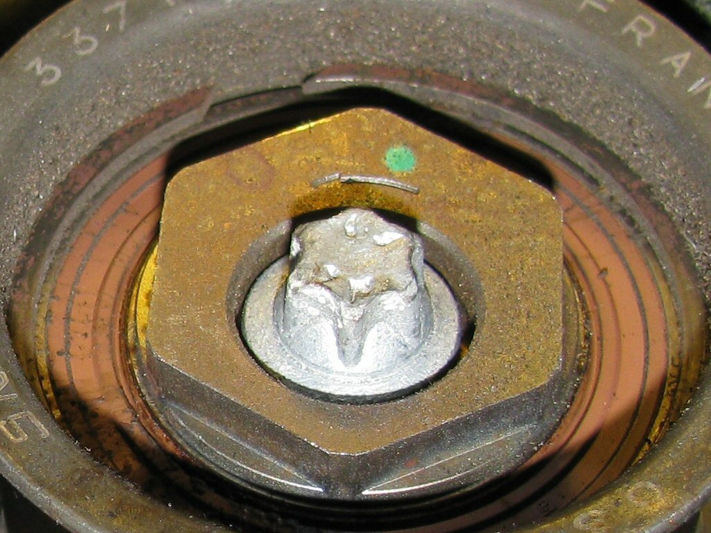
- Make a note of the original position of the eccentric on the upper idler pulley. Mine was close to 9 o'clock.
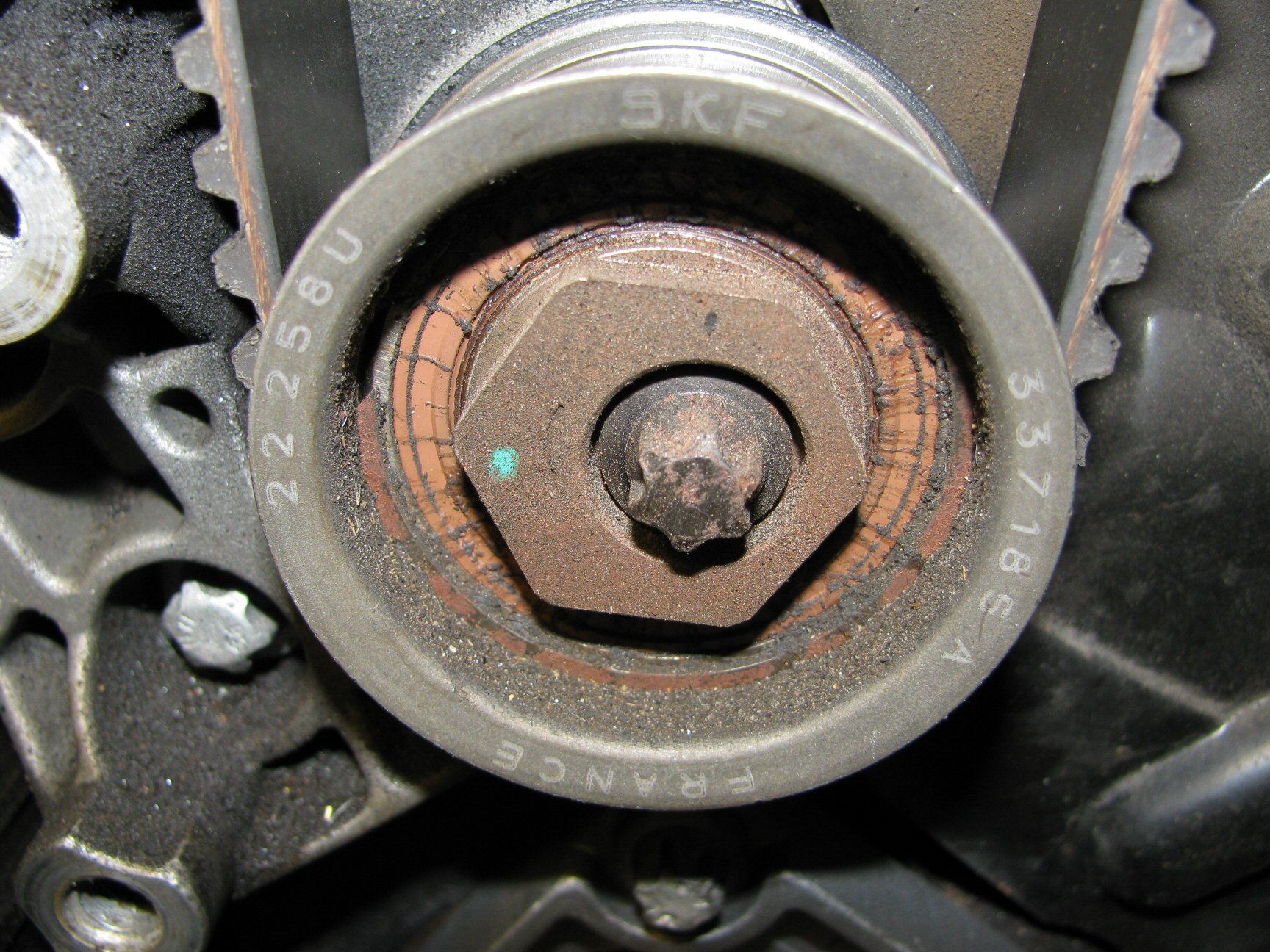
Upper idler pulley. Note the location of the green dot indicating a good initial position of 9 o'clock. Photo courtesy of Gregory Bender.
- Remove the bolt securing the upper idler pulley in place. Remove the pulley and take note of any spacers behind the pulley.
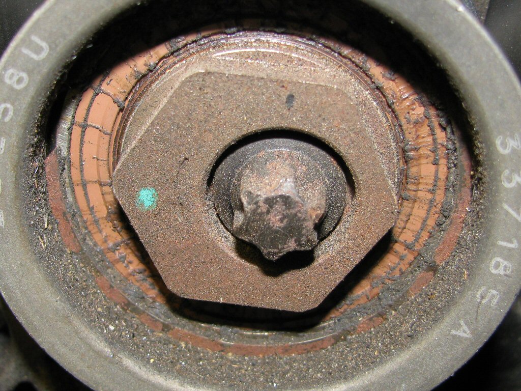
- Make a note of the original position of the eccentric on the lower idler pulley. Mine was close to 12 o'clock.
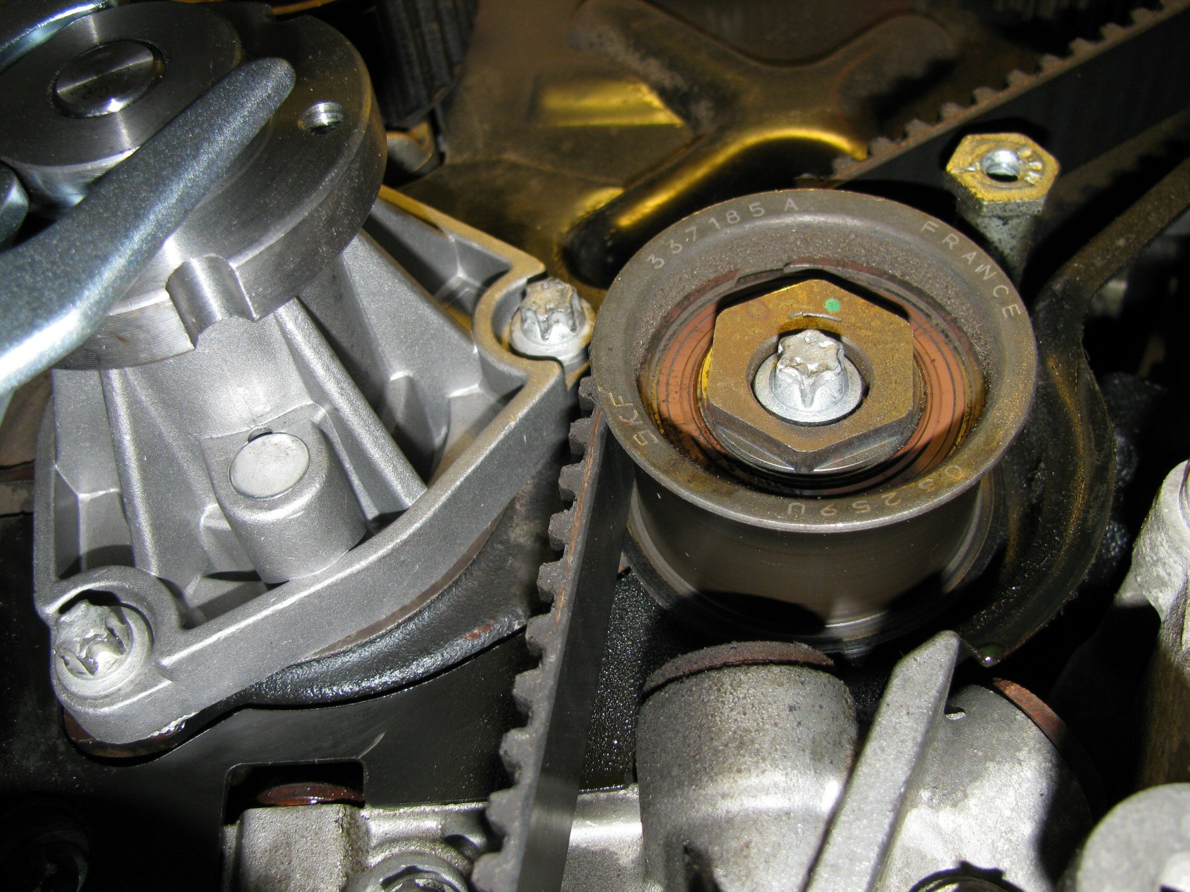
Lower idler pulley. Note the location of the green dot indicating a good initial position of 12 o'clock. Photo courtesy of Gregory Bender.
- Remove the bolt securing the lower idler pulley in place. Remove the pulley and take note of any spacers behind the pulley.
- Remove the belt.
- Compare the old belt with the new belt. Make sure the number of teeth are correct and that you know which lines correspond to your application.
- Fit the new tensioning pulley. Do not tighten. If the new pulley comes with a new spacer, make sure it is the same thickness as the old spacer. If not, use the old spacer.
- Fit the new upper idler pulley. Do not tighten. If the new pulley comes with a new spacer, make sure it is the same thickness as the old spacer. If not, use the old spacer.
- Do not fit the lower idler pulley just yet.
- Fit the belt. I found the following method worked very well for me:
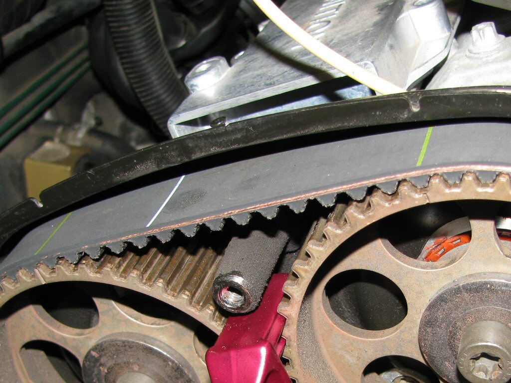
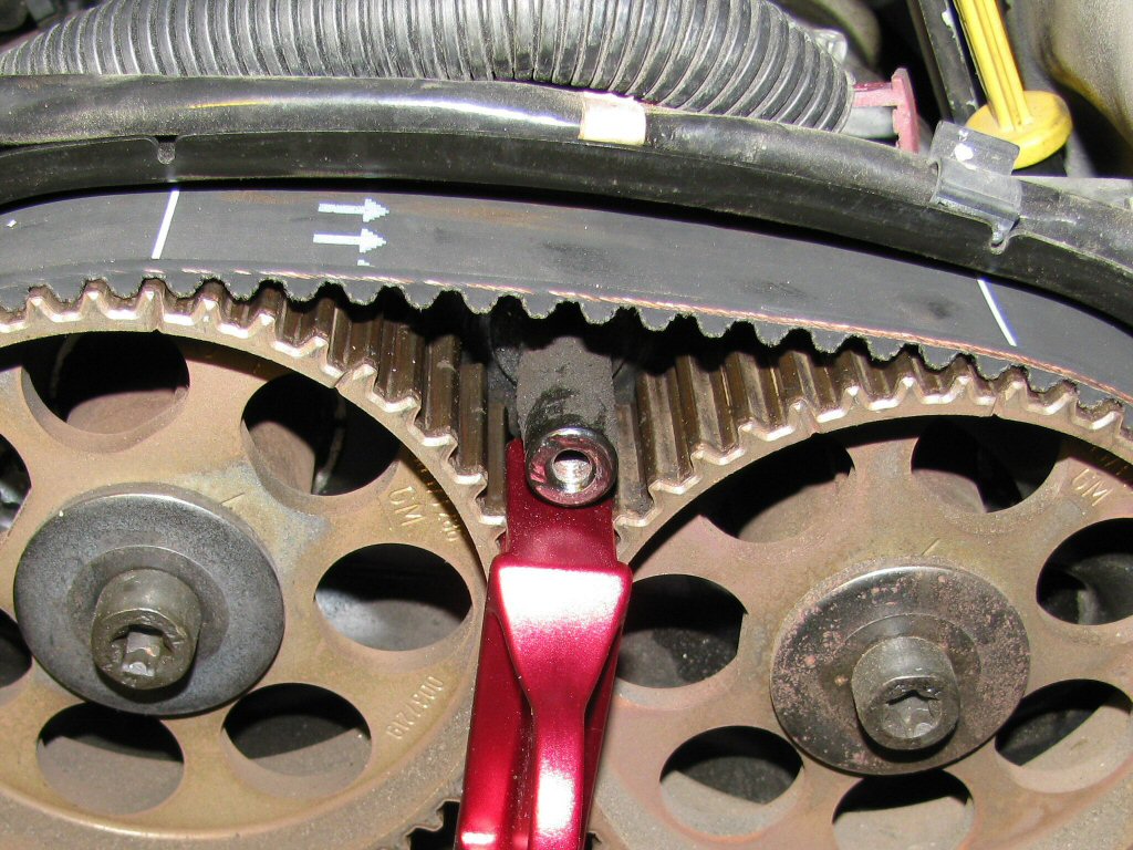
- Start by fitting the belt to the crankshaft so that the double green lines are aligned with the crankshaft notches. Fit the wedge piece so that the belt does not move from the crankshaft.
New belt positioned on the crankshaft pulley with the orange plastic wedge in place. Note the double green lines on the belt. Photo courtesy of Gregory Bender.
- Fit belt around tensioner.
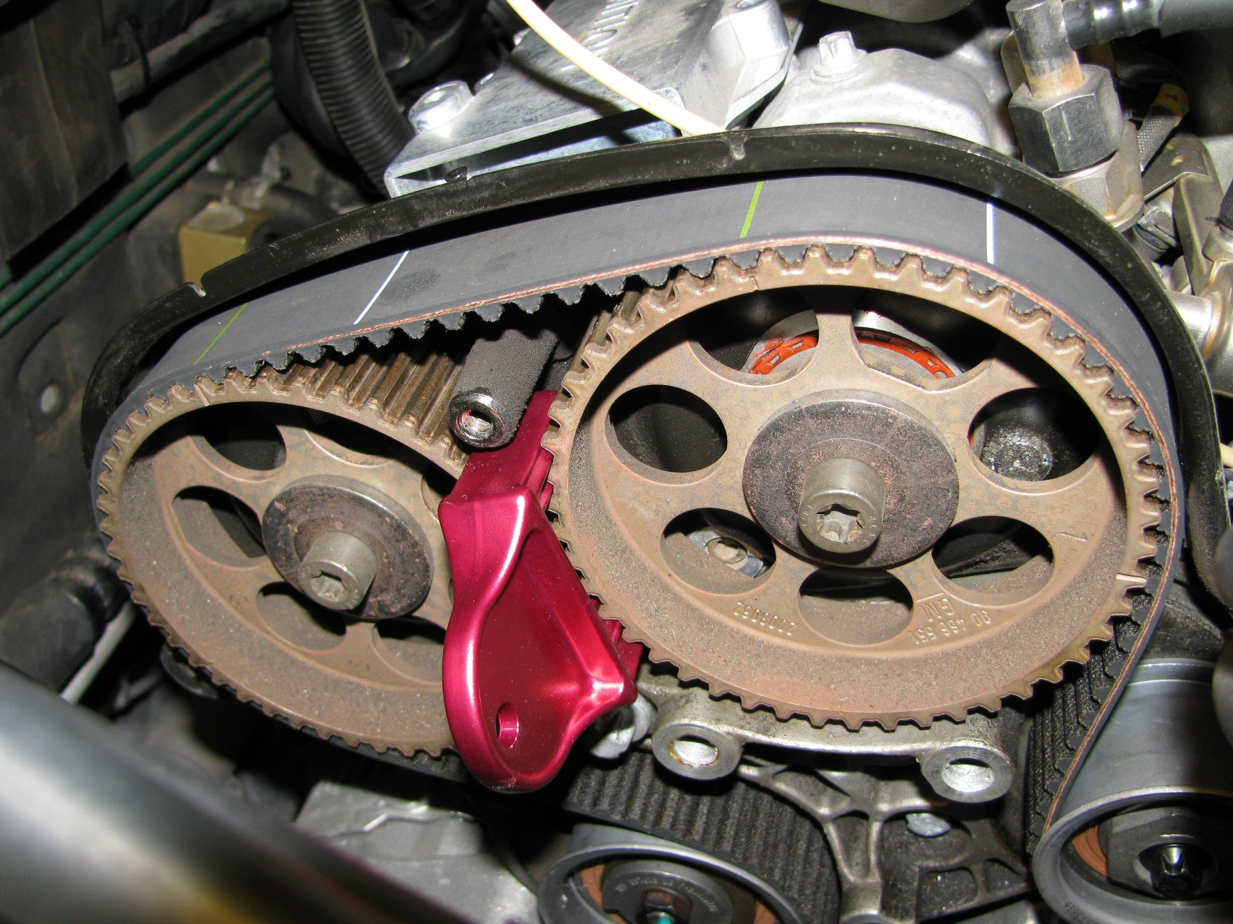
- Fit belt around camshaft pulleys 1 and 2, making sure the green lines on the belt align perfectly with the notches in the camshaft pulleys.
New belt positioned on camshaft pulleys 1 and 2. Note the green lines on the belt. Photo courtesy of Gregory Bender.
- Fit belt around the upper idler pulley.
- Fit belt around camshaft pulleys 3 and 4, making sure the white lines on the belt align perfectly with the notches in the camshaft pulleys.
New belt positioned on camshaft pulleys 3 and 4. Note the white lines on the belt. Note also the arrows indicating the direction of belt rotation. Photo courtesy of Gregory Bender.
- Start by fitting the belt to the crankshaft so that the double green lines are aligned with the crankshaft notches. Fit the wedge piece so that the belt does not move from the crankshaft.
- Fit the new lower idler pulley. Do not tighten. If the new pulley comes with a new spacer, make sure it is the same thickness as the old spacer. If not, use the old spacer.
- Before proceeding, verify the following:
- Crankshaft and camshaft pulleys have not moved. They shouldn't, as you've got them locked down.
- Double green lines on the belt are aligned with the notch on the hub for the crankshaft pulley.
New belt positioned on the crankshaft pulley. Note the double green lines on the belt. Photo courtesy of Gregory Bender.
- Single green lines on the belt are aligned with the corresponding notches on camshaft pulleys 1 and 2.
New belt positioned on camshaft pulleys 1 and 2. Note the green lines on the belt. Photo courtesy of Gregory Bender.
- Single white lines on the belt are aligned with the corresponding notches on camshaft pulleys 3 and 4.
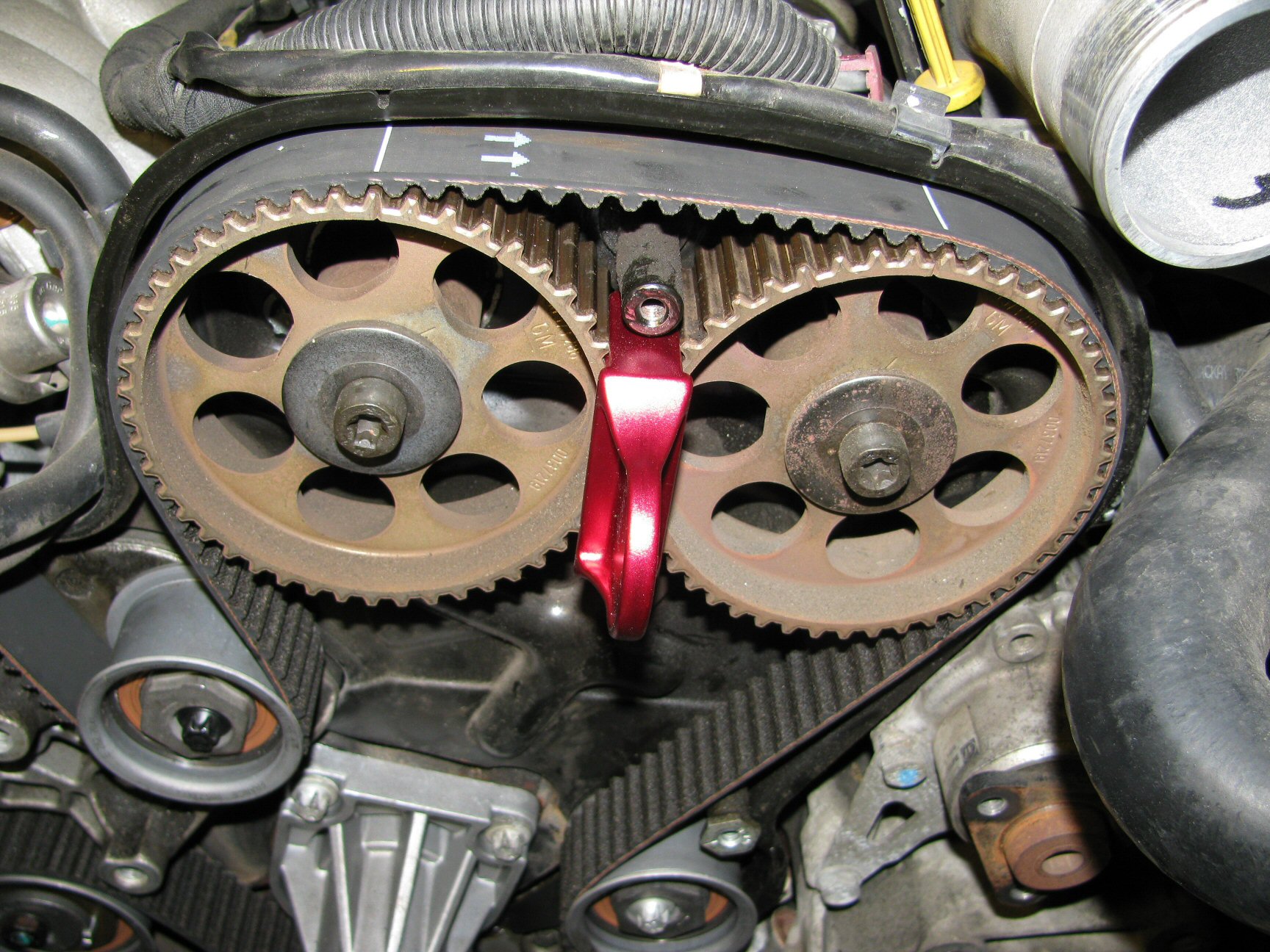
New belt positioned on camshaft pulleys 3 and 4. Note the white lines on the belt. Note also the arrows indicating the direction of belt rotation. Photo courtesy of Gregory Bender.
- The belt should be roughly centered on the toothed pulleys. I found that as I rotated the crankshaft, the belt would actually move a bit to its desired location and then just stay there. No need to worry about belt position as long as it consistent on all the toothed pulleys.
- Give the tensioning pulley a bit of tension just to keep the belt in place. Snug the retaining nut such that it won't back off...but the final torque of 15 pound feet is not yet required.
- Position the lower idler pulley so that the eccentric is located at 12 o'clock. Sung the retaining bolt such that it won't back off...but the final torque of 30 pound feet is not yet required. Note: The Saab WIS makes mention of using a special belt tension gauge. This tool is not needed. Once you set the tensioning pulley, it will provide all the tension that is needed.
Lower idler pulley. Note the location of the green dot indicating a good initial position of 12 o'clock. Photo courtesy of Gregory Bender.
- Position the upper idler pulley so that the eccentric is located at 9 o'clock. Sung the retaining bolt such that it won't back off...but the final torque of 30 pound feet is not yet required.
Upper idler pulley. Note the location of the green dot indicating a good initial position of 9 o'clock. Photo courtesy of Gregory Bender.
- Adjust the tensioning pulley so that the two alignment marks are aligned. Snug the retaining nut.
- Before proceeding, verify the following:
- The nut securing the tensioning pulley and the bolts securing the idler pulleys are good and snug. What you don't want to happen is for them to loosen up as you are rotating the crankshaft, the belt get off a tooth, and then the timing is off. Not good.
- Remove the wedge piece, the lock on the crankshaft, and both locks on the camshaft pulleys.
- Rotate the engine 2 complete revolutions. Just before the crankshaft is at TDC, fit the crankshaft lock and rotate the crankshaft to TDC.
- Fit the alignment jig and check that the notches on the camshaft pulleys match the marks on the alignment jig. Sorry, I've no picture of the alignment jig. It looks like a figure
8
and fits inside both pulleys. Once you fit it, it will be immediately obvious whether or not the pulleys are in the proper location.- If notches on the camshaft pulley have rotated past the marks on the alignment jig, then the idler pulley is too tight. Loosen it just a bit and try again.
- If notches on the camshaft pulley have not yet reached the marks on the alignment jig, then the idler pulley is too loose. Tighten it just a bit and try again.
- There exists some interaction between the idler pulleys. For example, if you tighten the upper idler pulley, it will affect both camshafts 1 and 2 as well as camshafts 3 and 4. Camshafts 1 and 2 will be rotated more clockwise while camshafts 3 and 4 will be rotated more counter-clockwise. Therefore, you may very well need to tighten one idler pulley and loosen the other. You will just have to use trial and error to get it right.
- Each time you adjust the idler pulleys, you will need to check and adjust the tensioner pulley.
- Once you've adjusted the pulleys, remove the lock on the crankshaft and rotate the engine 2 more revolutions. Fit the crankshaft lock and recheck the pulleys with the alignment jig. Keep adjusting, rotating, and checking until all pulleys are properly aligned.
- Once you are 100% satisfied with the alignment, do a final check/adjustment on the tensioning pulley. From what I've read, the alignment marks on the tensioning pulley should be just a hair on the tight side. By a
hair
, I mean 0.04 inch. You will probably notice that the alignment marks move around a bit as you rotate the engine. No need for concern, this is just the normal spring-loaded tensioner doing it's job as more or less valve spring resistance is encountered. - Using a torque wrench, tighten the nut on the tensioning pulley to 15 pound feet.
- Using a torque wrench, tighten the bolts on the idlers pulleys to 30 pound feet.
- That's it. You are now ready to put everything back together.
Part 3: Assembly
Assembly is pretty much the reverse of disassembly. A couple of points...
- The Saab WIS says to use thread locking compound on the three bolts securing the water pump pulley to the water pump. I used medium strength thread locking compound. Torque for these bolts is 6 pound feet.
- The Saab WIS says to use thread locking compound on the three bolts securing the steering pump pulley to the steering pump. I used medium strength thread locking compound. Torque for these bolts is 15 pound feet.
- The Saab WIS says the torque for the crankshaft pulley is 15 pound feet.
- I applied anti-seize compound to most all of the bolts to which I didn't apply thread locking compound.
Part 4: Start the car
Nervous? You better believe I was. There isn't anything you can do at this point other than turn the key and start the engine. Mine was a success. I hope yours is too.