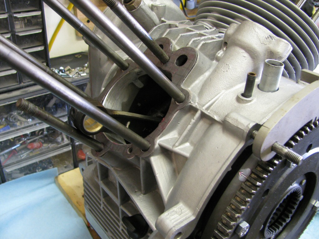
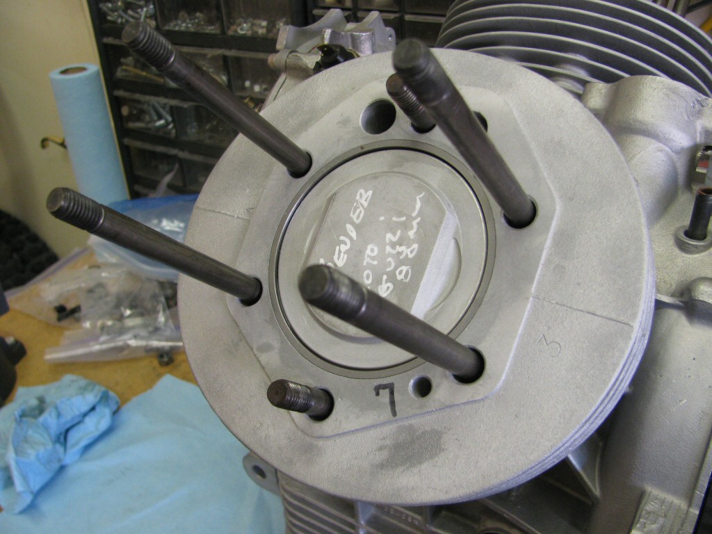
Alright, let's work on the left side. Here the base gasket is in placed (greased).
Photo courtesy of Gregory Bender.
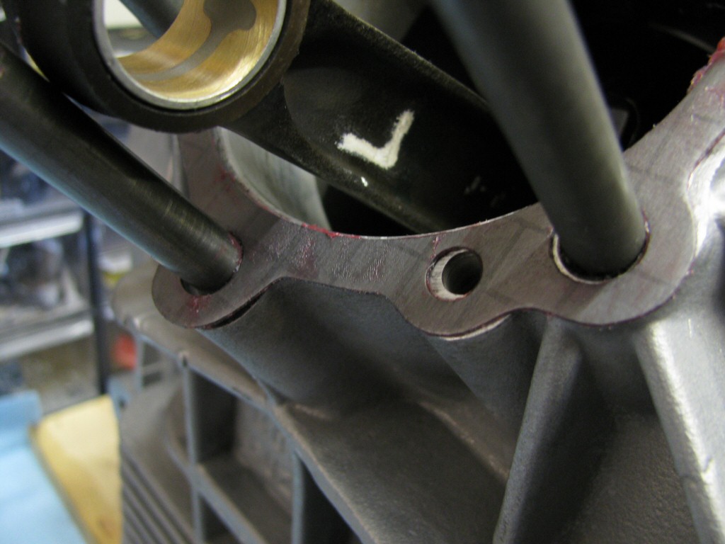
Oil return hole is correctly aligned.
Photo courtesy of Gregory Bender.
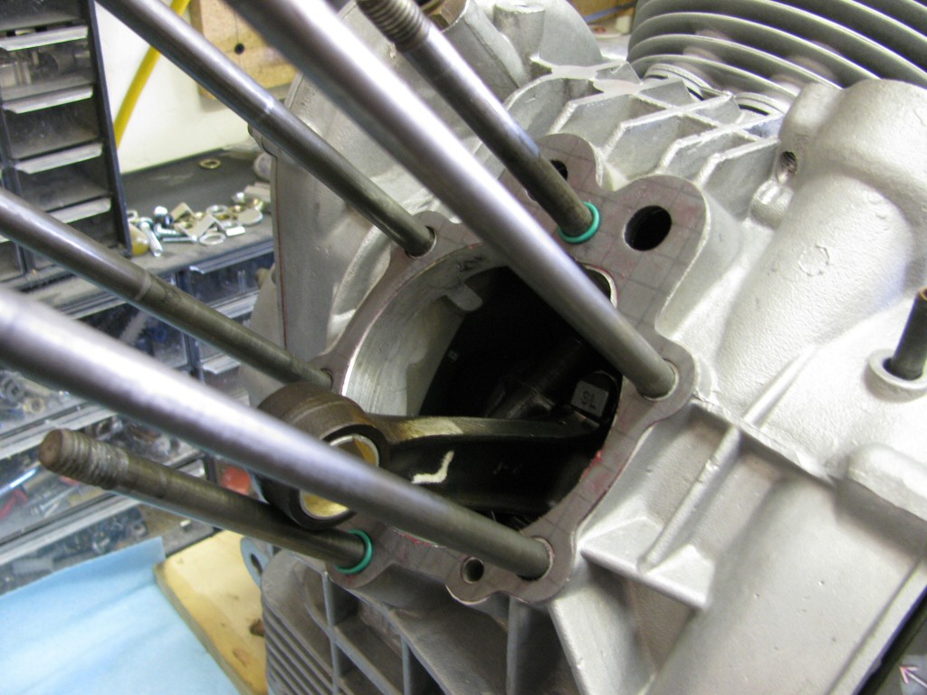
O-rings on the 12 o'clock and 6 o'clock studs.
Photo courtesy of Gregory Bender.
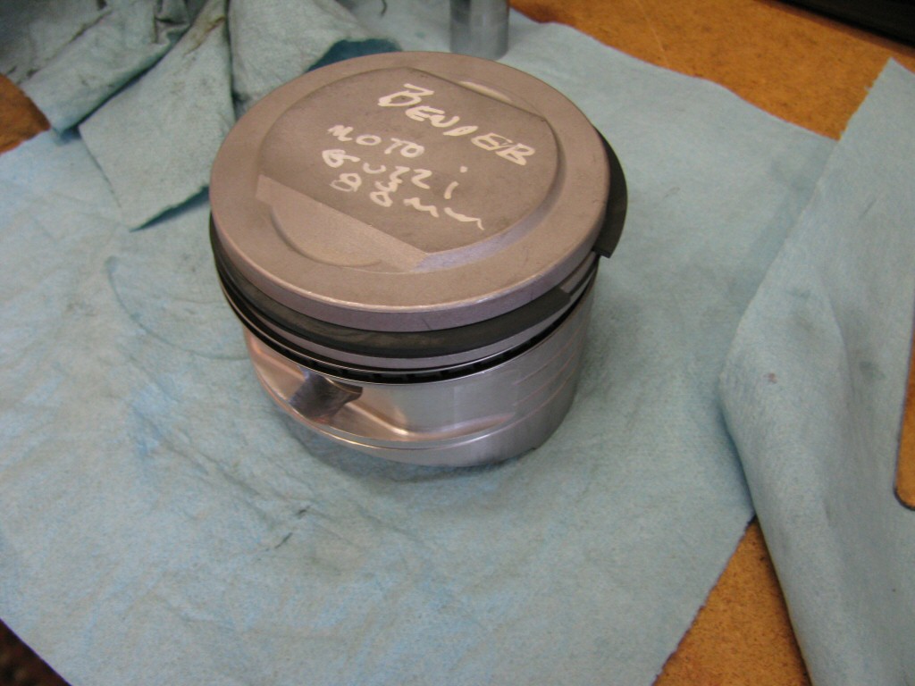
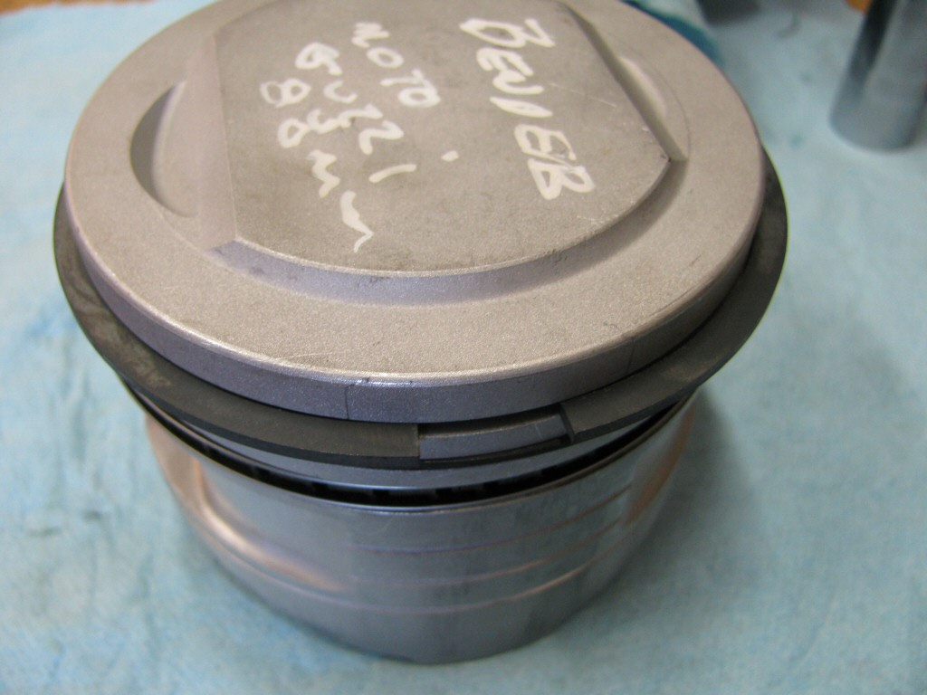
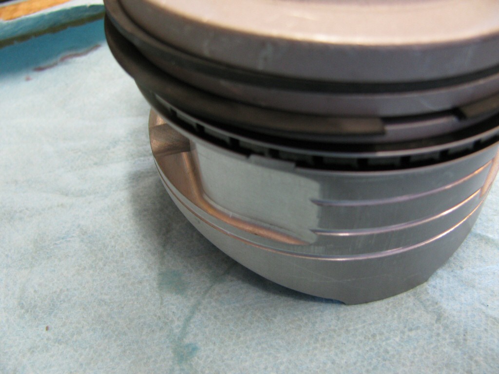
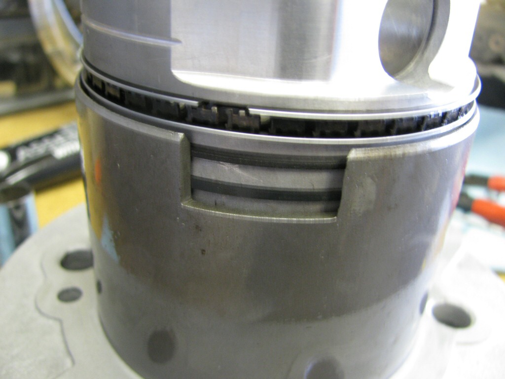
Rings fit to the left piston. This series of photos is intended to show the careful ring gap placement, as per the instructions provided by the piston ring manufacturer (TotalSeal).
Photo courtesy of Gregory Bender.
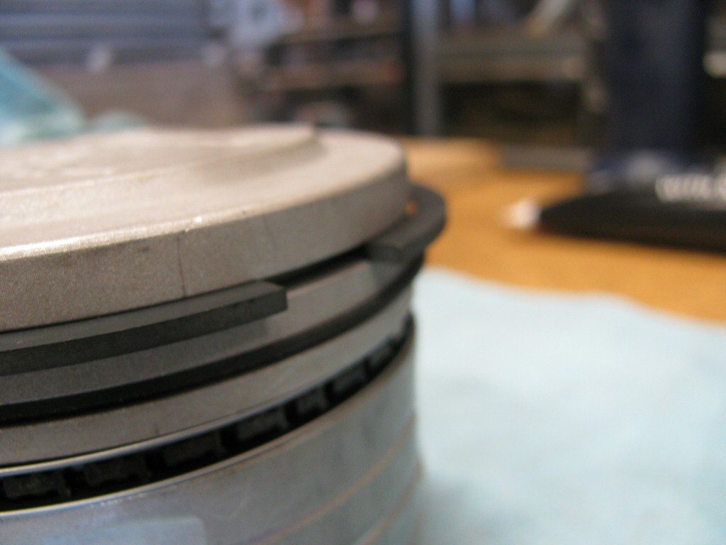
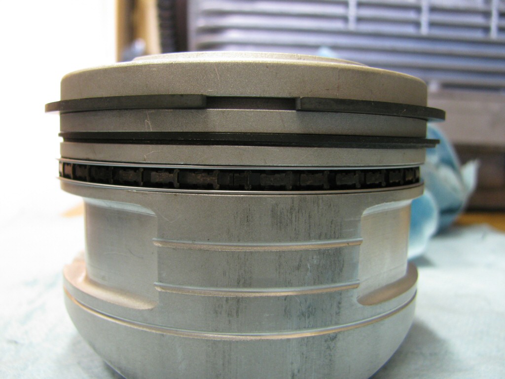
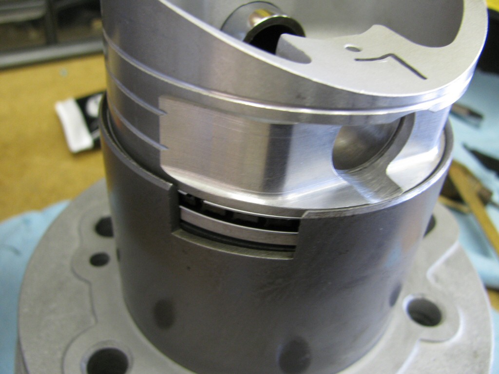
Rings fit to the left piston. This series of photos is intended to show the careful ring gap placement, as per the instructions provided by the piston ring manufacturer (TotalSeal).
Photo courtesy of Gregory Bender.
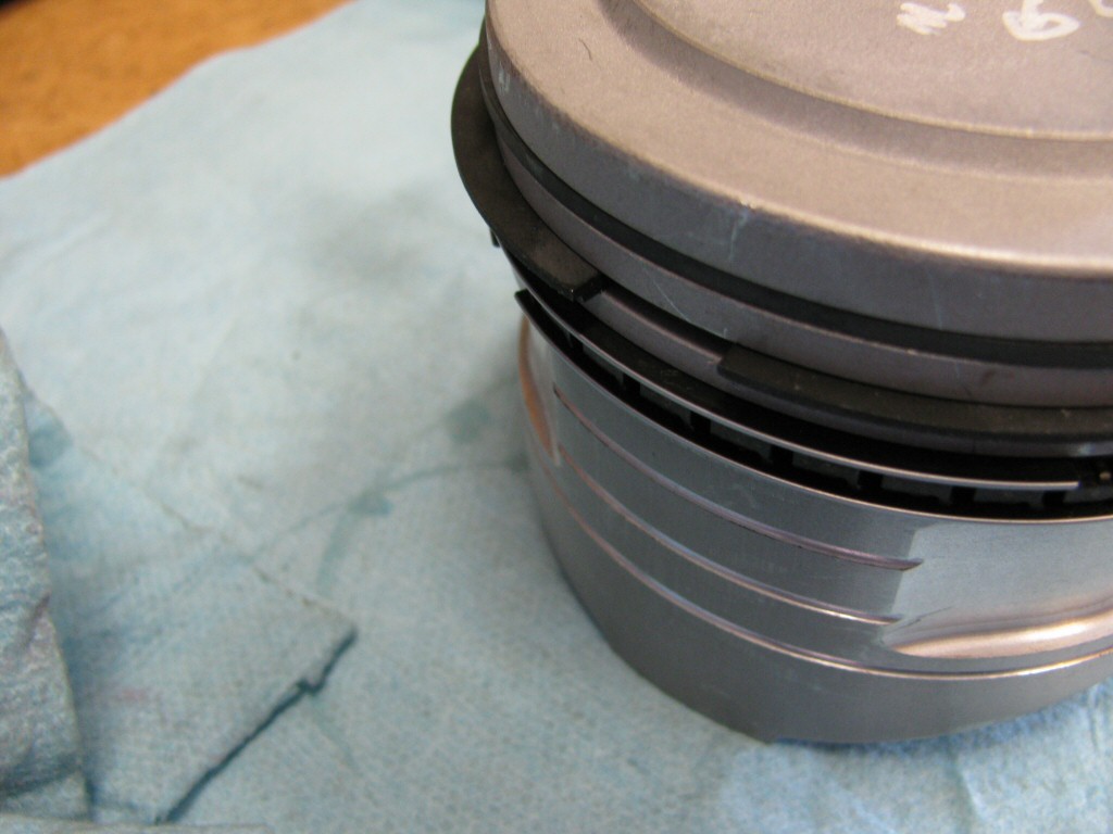
Rings fit to the left piston. This series of photos is intended to show the careful ring gap placement, as per the instructions provided by the piston ring manufacturer (TotalSeal).
Photo courtesy of Gregory Bender.
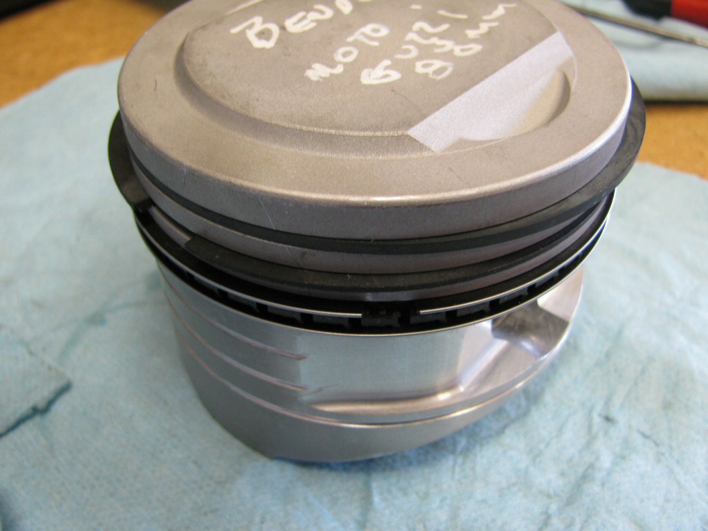
Rings fit to the left piston. This series of photos is intended to show the careful ring gap placement, as per the instructions provided by the piston ring manufacturer (TotalSeal).
Photo courtesy of Gregory Bender.
Rings fit to the left piston. This series of photos is intended to show the careful ring gap placement, as per the instructions provided by the piston ring manufacturer (TotalSeal).
Photo courtesy of Gregory Bender.
Rings fit to the left piston. This series of photos is intended to show the careful ring gap placement, as per the instructions provided by the piston ring manufacturer (TotalSeal).
Photo courtesy of Gregory Bender.
Rings fit to the left piston. This series of photos is intended to show the careful ring gap placement, as per the instructions provided by the piston ring manufacturer (TotalSeal).
Photo courtesy of Gregory Bender.
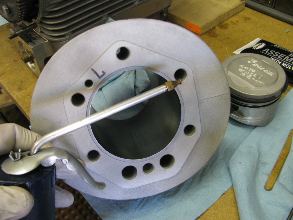
I oiled the iron liner inside the cylinder. Some say not to, but I do not want any rust to form before Roy starts the engine the first time.
Photo courtesy of Gregory Bender.
Top compression ring slid into the cylinder.
Photo courtesy of Gregory Bender.
Middle scrapper ring slid into the cylinder.
Photo courtesy of Gregory Bender.
Oil ring slid into the cylinder.
Photo courtesy of Gregory Bender.
I fit a new circlip to one side of the piston.
Photo courtesy of Gregory Bender.
Assembly lube applied to the piston for the wrist pin.
Photo courtesy of Gregory Bender.
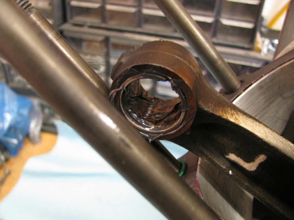
Assembly lube applied to the small end of the connecting rod.
Photo courtesy of Gregory Bender.
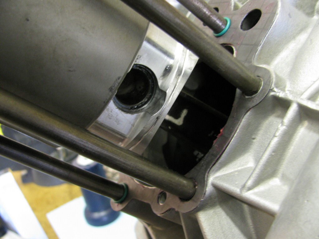
Circlip in place on the rear side of the piston.
Photo courtesy of Gregory Bender.
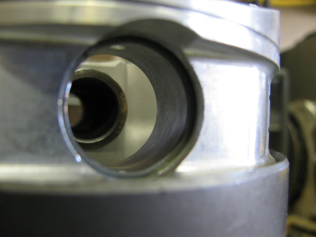
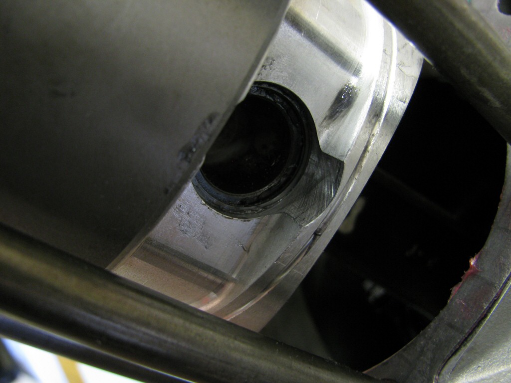
A closer view of the circlip in place on the rear side of the piston.
Photo courtesy of Gregory Bender.
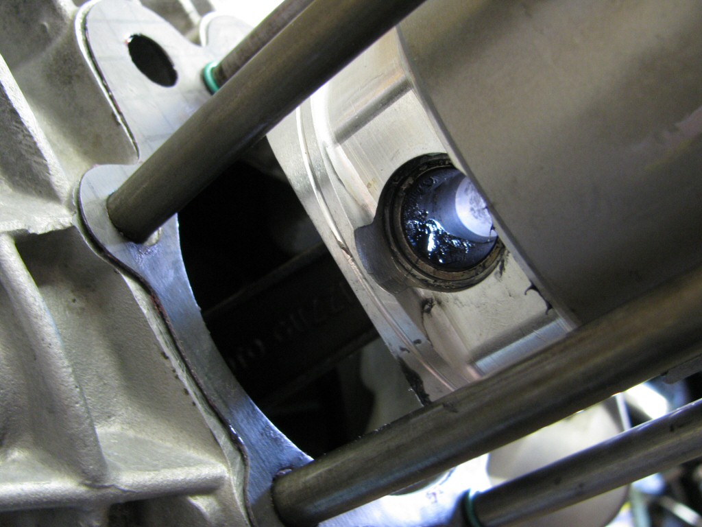
Circlip in place on the front side of the piston.
Photo courtesy of Gregory Bender.
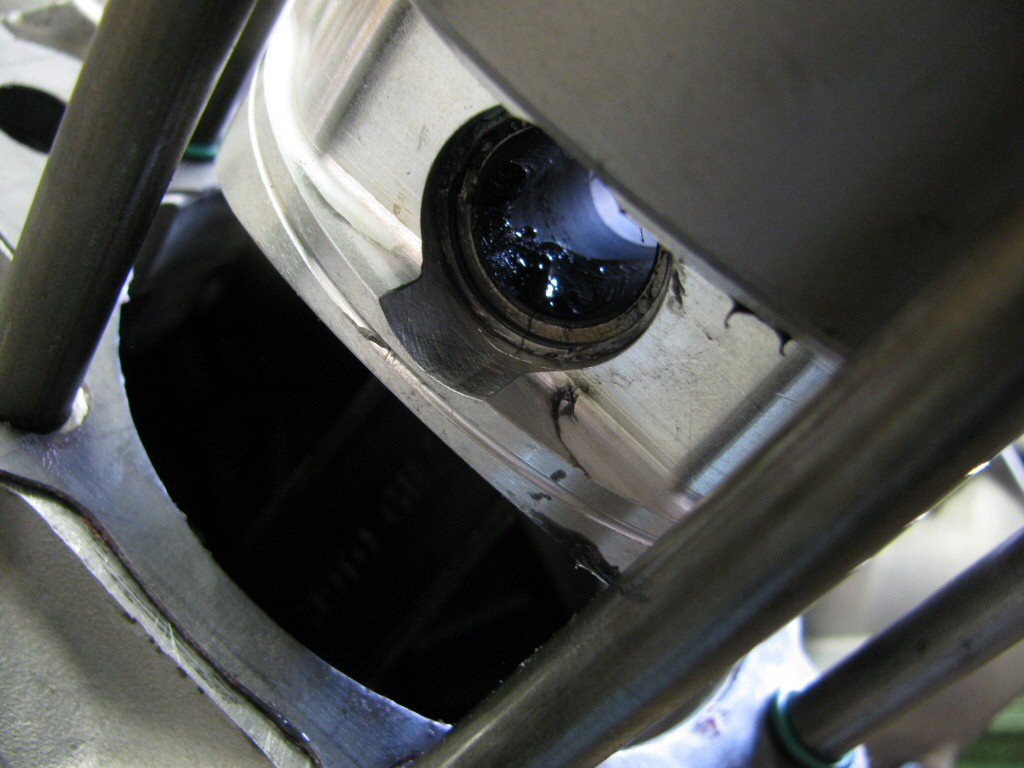
A closer view of the circlip in place on the front side of the piston.
Photo courtesy of Gregory Bender.
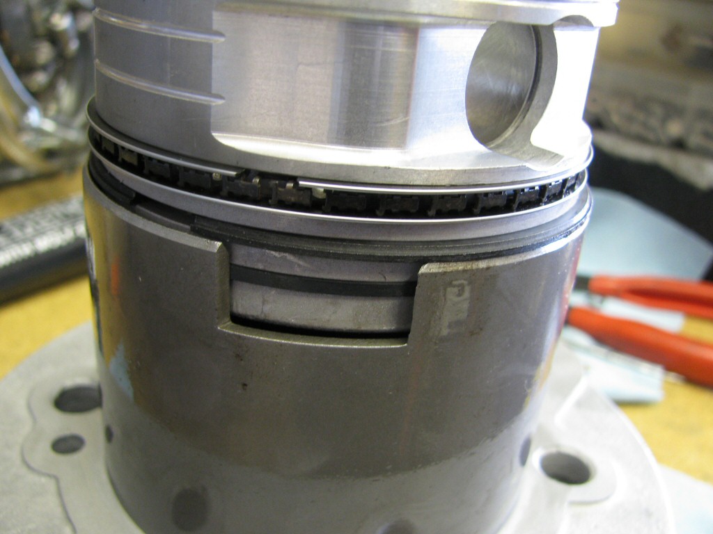
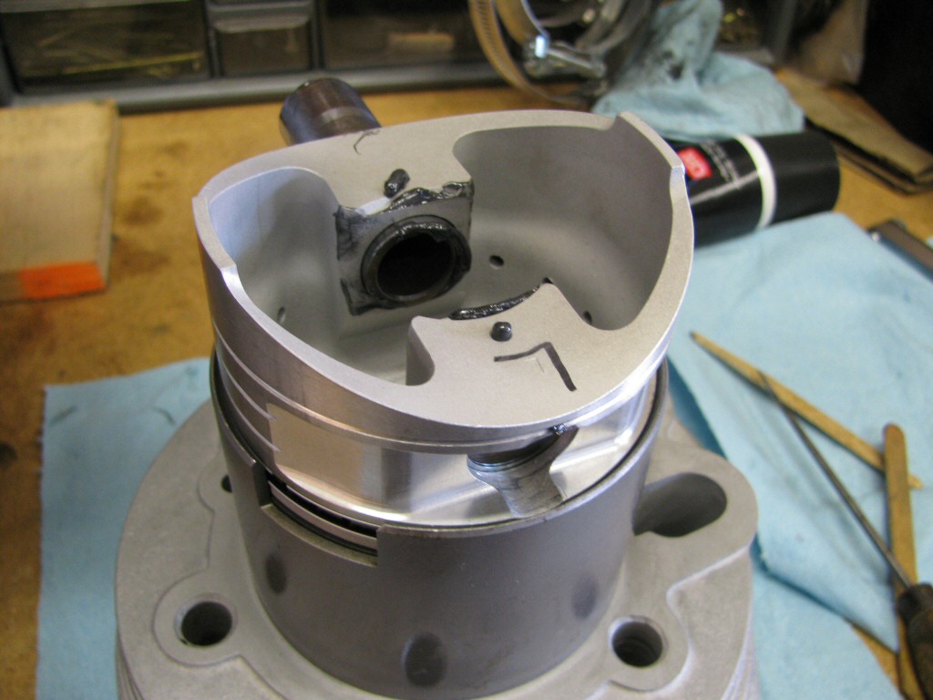
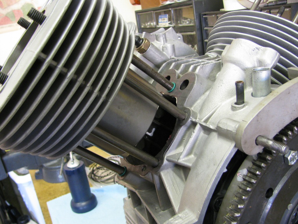
The cylinder slid down a bit to cover the entire piston.
Photo courtesy of Gregory Bender.
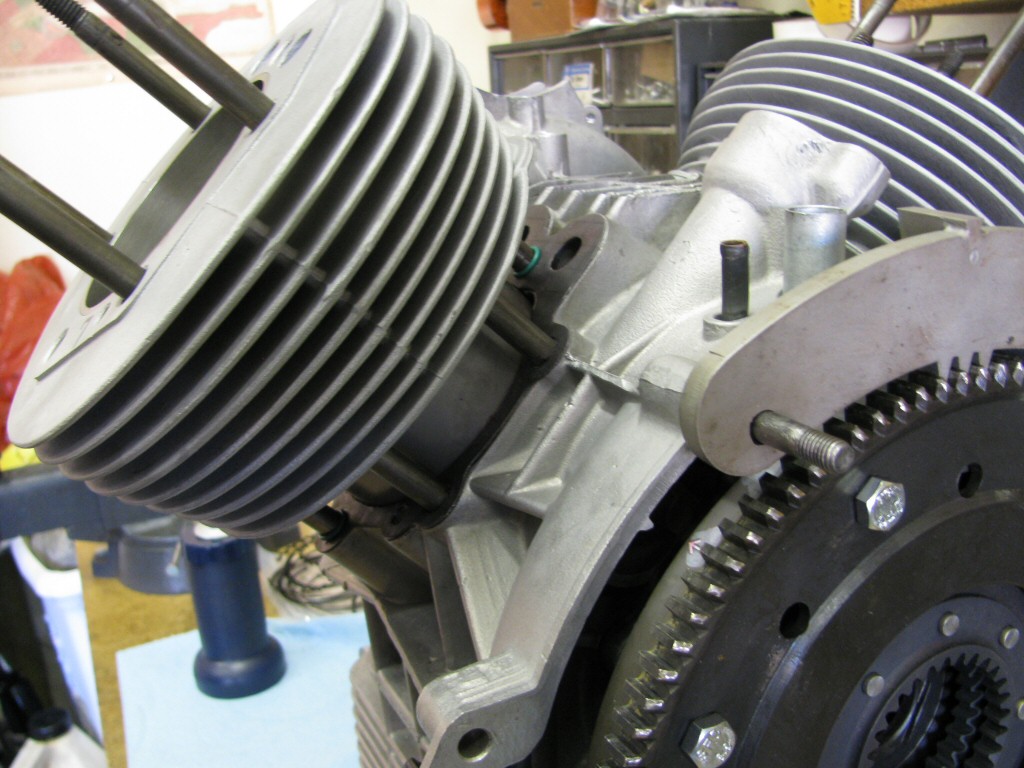
The cylinder entering the block.
Photo courtesy of Gregory Bender.
The cylinder fully in place with the piston at TDC.