Step 3: Install the sub-harness that connects the left handlebar switch to the headlight bucket
Applicable to these part numbers:
- MG# 12747320
- MG# 12746020
- MG# 12746001
Warning:
It is very easy to destroy original or aftermarket switches when using a conventional soldering iron. Even if you know exactly what you are doing and are very experienced with soldering procedures, the switches can very easily be rendered useless. Rather than using solder, I strongly recommend the following:
- Use a conductive epoxy to secure the wires to the switch. Most epoxies, including JB Weld, do not conduct electricity. MG Chemicals makes a conductive epoxy that I've used with excellent results (part number 8331D). Atom Adehesives AA-PROD 123 is a less expensive epoxy that Charlie Mullendore of Antietam Classic Cycle reports works well. Nick Rossi contacted Atom Adhesives directly and found that AA-Duct 902 is the
most conductive epoxy
and that AA-Duct 916 ismore suitable for motorcycle applications as it is flexible once cured and will be more resistant to vibration
. Nick prefers the AA-Duct 916 (available from Amazon).
Connect the wires to the left handlebar switch
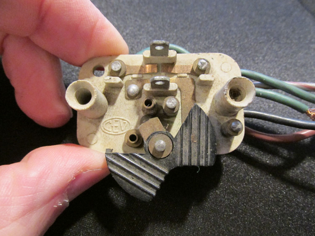
Photo courtesy of Gregory Bender.
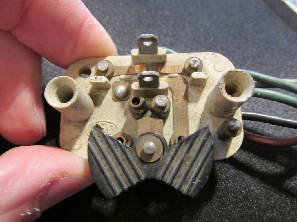
Photo courtesy of Gregory Bender.
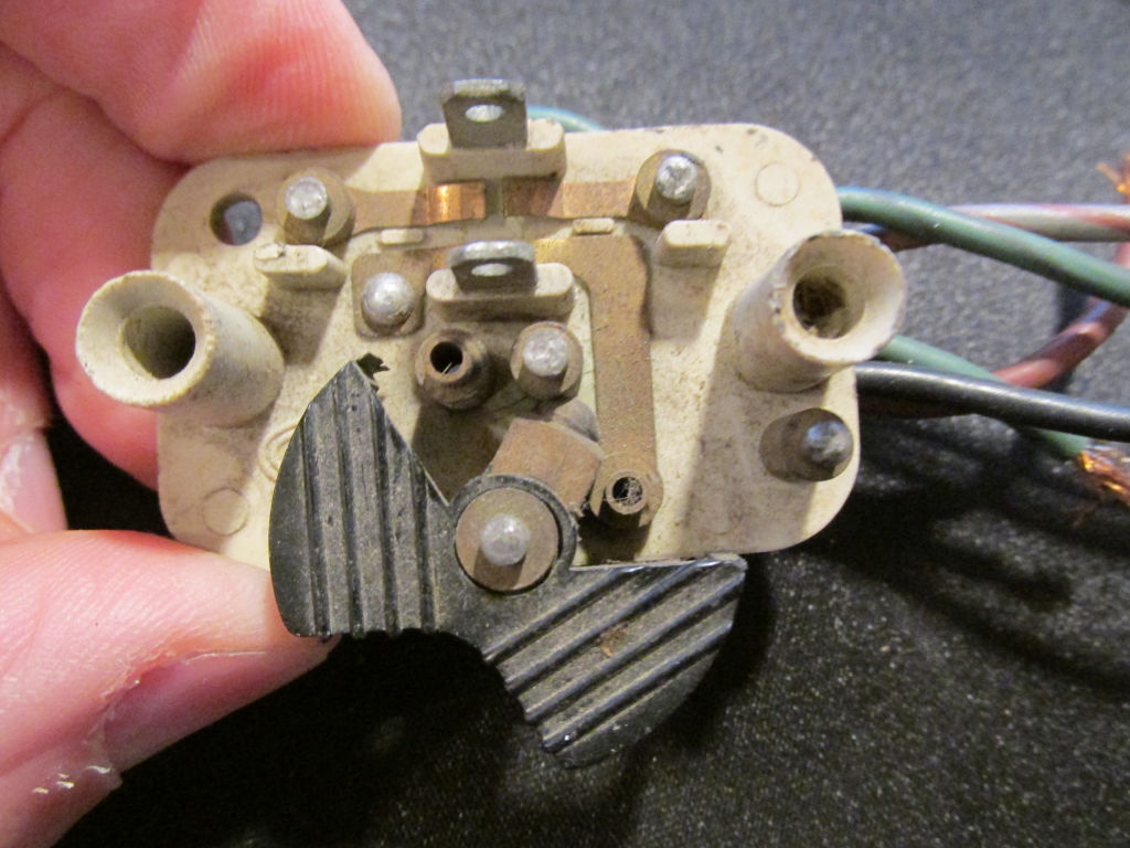
Photo courtesy of Gregory Bender.
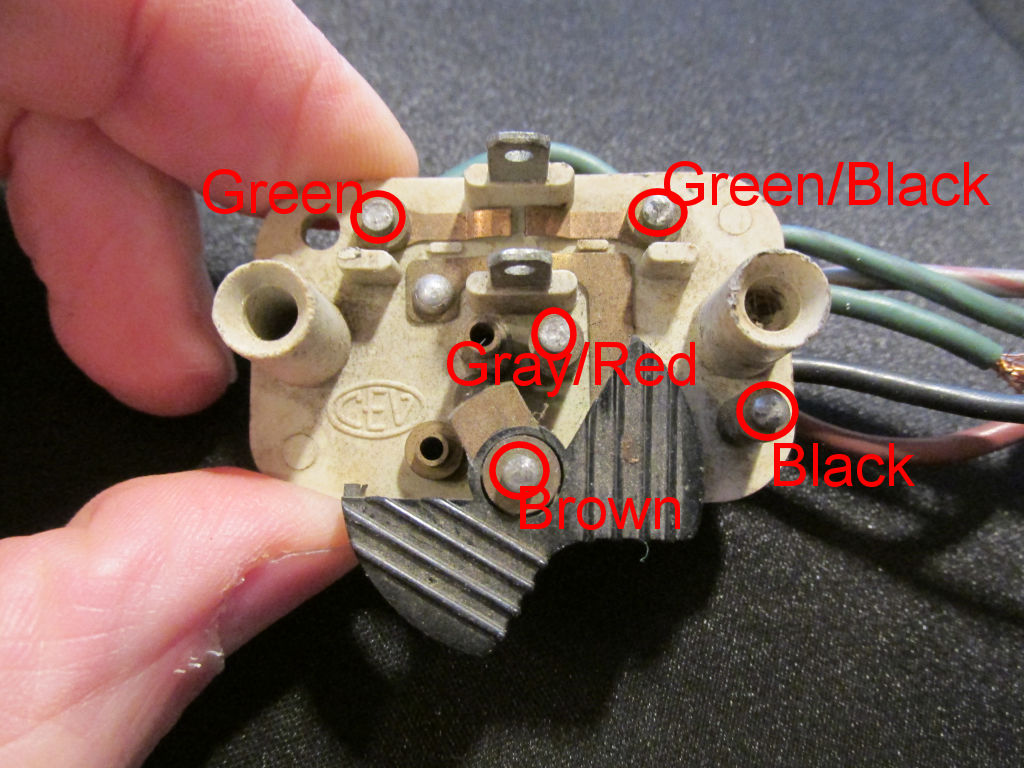
Photo courtesy of Gregory Bender.
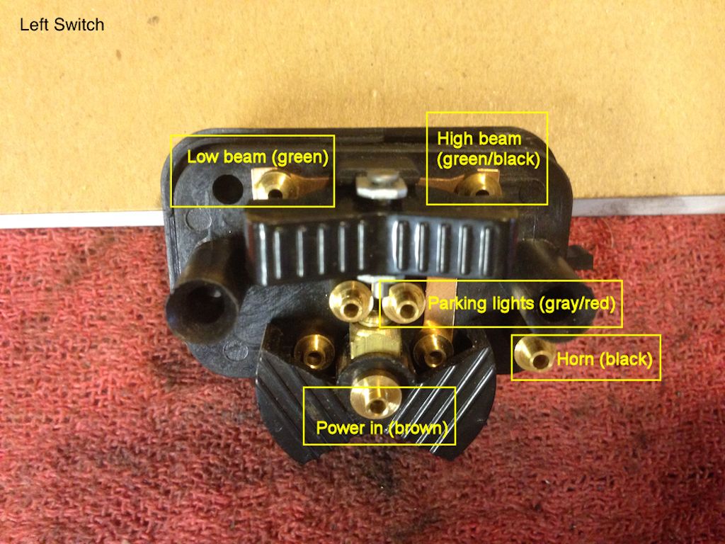
Photo courtesy of Stephen Gonzales.
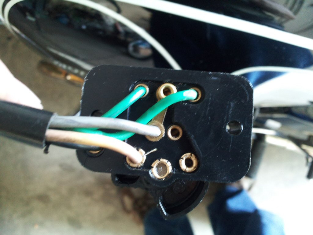
Photo courtesy of Al Zinn.
Make the left handlebar switch connections inside the headlight bucket
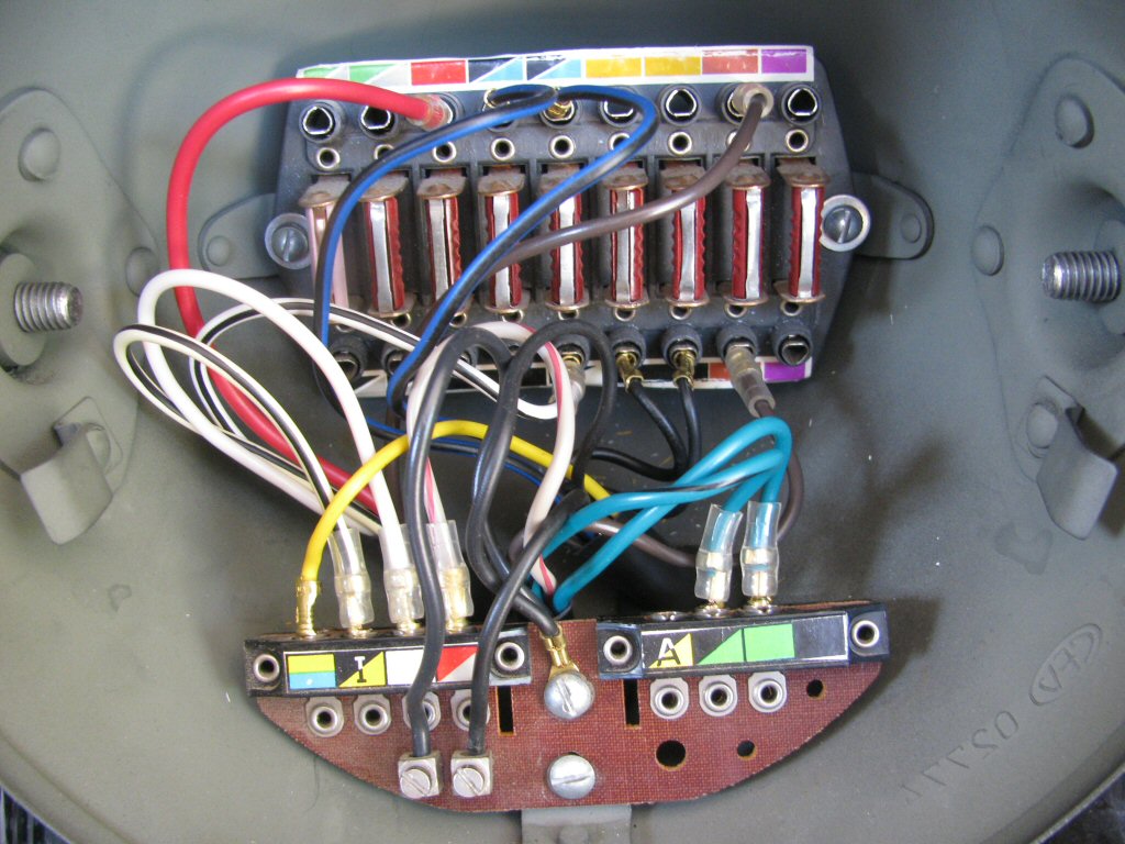
Photo courtesy of Gregory Bender.
- Route the wire from the switch, following the curve of the handlebar to where it meets the dash. Continue routing it down along the left side of the steering stem and into headlight bucket. At the headlight bucket, I tend to route the sheath through the larger hole on the right side.
- The brown wire with the 4 mm male bullet terminal is plugged into the bottom of the fuse block: into receptacle eight (count from the left, as when facing the headlight bucket).
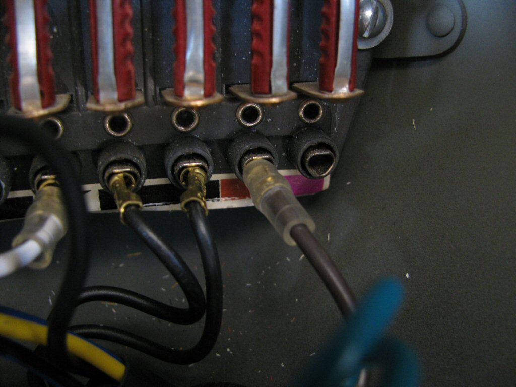
Photo courtesy of Gregory Bender.
- The gray/red wire with the 4 mm male bullet terminal is plugged into the far left side of the distribution panel: into the fourth left/front receptacle (count from the left as when facing the headlight bucket).
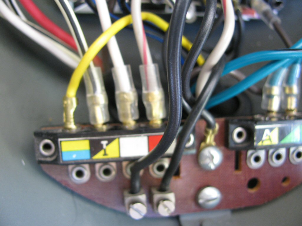
Photo courtesy of Gregory Bender.
- The green wire with the 4 mm male bullet terminal is plugged into the far right side of the distribution panel: into the right/rear receptacle (count from the left as when facing the headlight bucket).
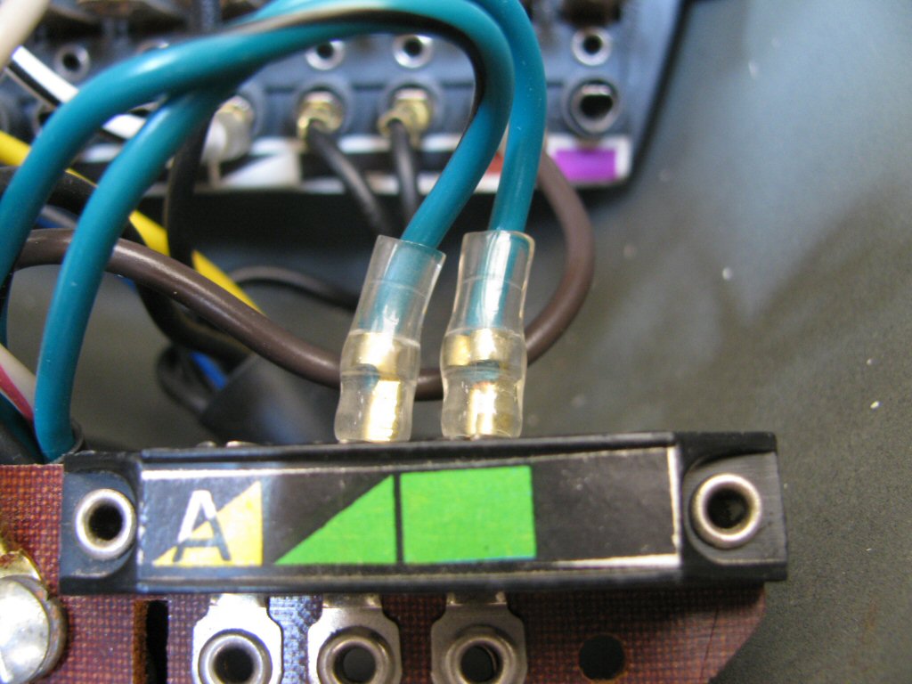
Photo courtesy of Gregory Bender.
- The green/black wire with the 4 mm male bullet terminal is plugged into the far right side of the distribution panel: into the left/rear receptacle (count from the left as when facing the headlight bucket).
Photo courtesy of Gregory Bender.
- The black wire with insulation stripped and the wires tinned with solder is secured to either of the set screw terminals on the distribution panel.
Photo courtesy of Gregory Bender.
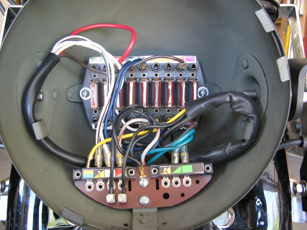
Photo courtesy of Gregory Bender.