Custom 1: Install Gregory Bender's custom headlight and starter relay harness and bracket
Applicable to these part numbers:
The vast majority of the wiring connections are already made for you with this harness (This relay solution is available for purchase).
- I route the relay harness along the right side of the frame, all the way from the battery tray to the headlight bucket. At the headlight, I route the wires through the large right hole in the headlight bucket.
- Mount the bracket to your existing voltage regulator bracket.
Early voltage regulator bracket without the integrated starter relay bracket
If you have the early bracket without the integrated starter relay mount, then you will need to remove the voltage regulator bracket so that you can access the mounting fasteners that secure the voltage regulator to the bracket. Remove the voltage regulator from the bracket, insert the new bracket, and bolt the voltage regulator back in place. This
sandwiches
the new bracket in place.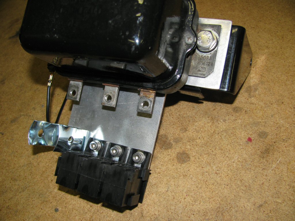
Photo courtesy of Gregory Bender.
Later voltage regulator bracket with the integrated starter relay bracket
If you have the later bracket with the integrated starter relay mount, then you can simply bolt on the new relay bracket using the included stainless steel hardware. The aluminum spacers go between the new bracket and the original mount, providing needed clearance.
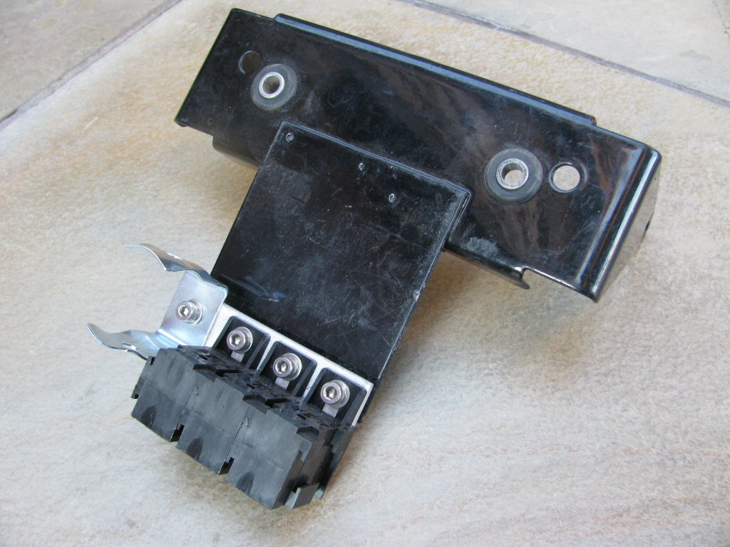
Photo courtesy of Gregory Bender.
- With the routing complete and the bracket installed, it is time to hook up the wires.
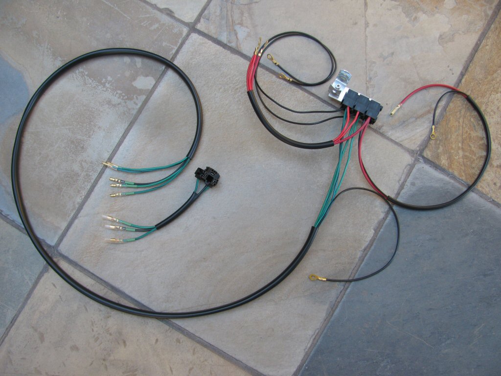
Photo courtesy of Gregory Bender.
- Inside the headlight bucket, the black, green and green/black wires (with green markers on them) plug directly into the headlight plug. Just match up the colors and tracers and plug them in.
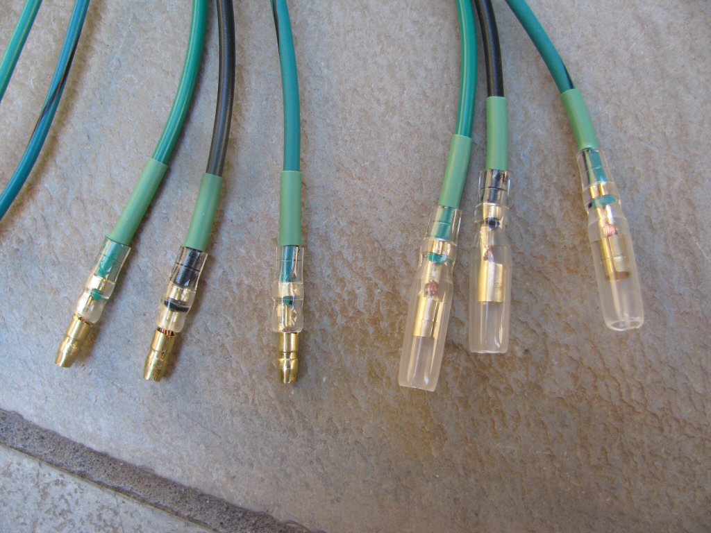
Photo courtesy of Gregory Bender.
- Inside the headlight bucket, the green and green/black wires (without green markers on them) plug into the distribution block, where the headlight plug would have originally been connected.
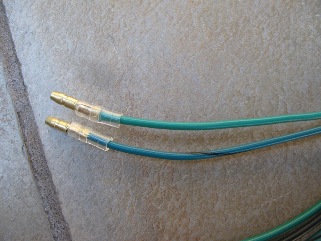
Photo courtesy of Gregory Bender.
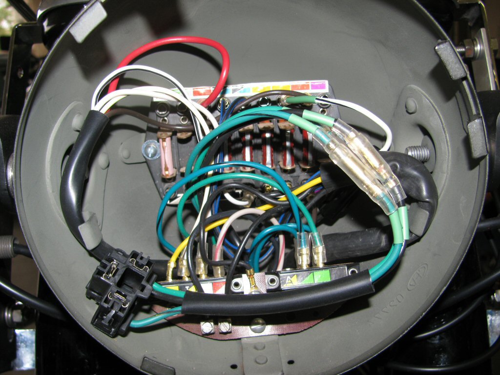
Photo courtesy of Gregory Bender.
- At the battery tray, the black wires from the relay sockets ground to the voltage regulator ground point.
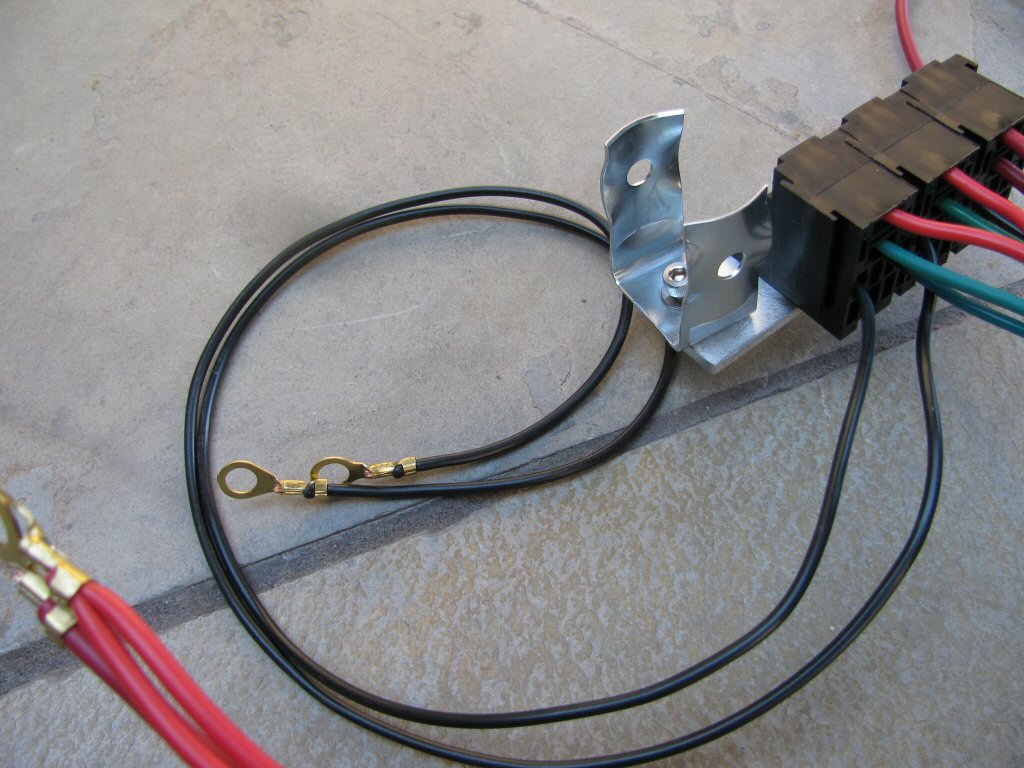
Photo courtesy of Gregory Bender.
- At the battery tray, the red wires connect to the battery positive terminal.
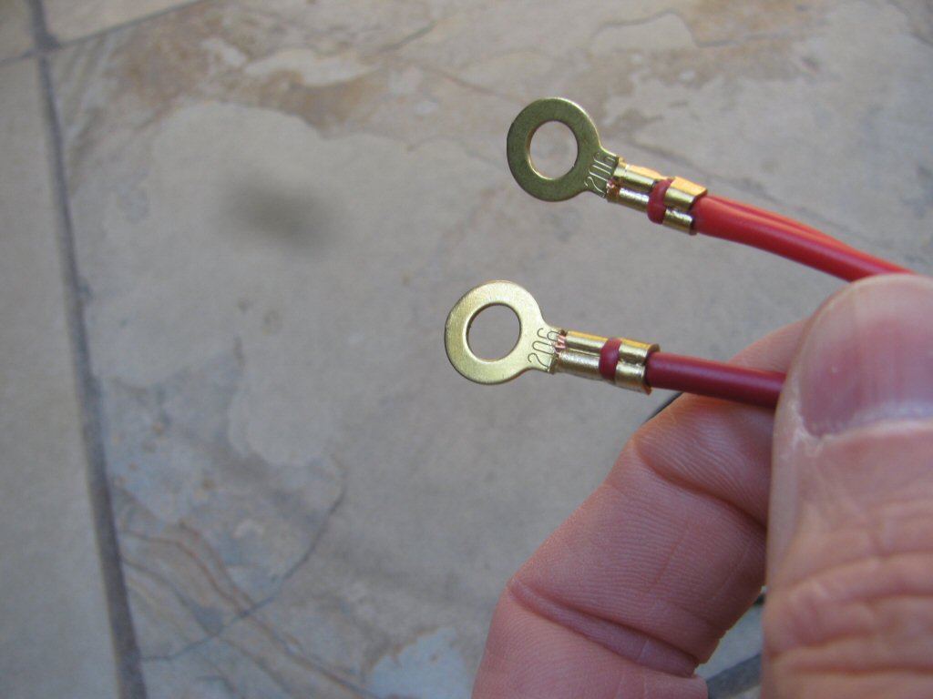
Photo courtesy of Gregory Bender.
- At the battery tray, the black wire from the main sheath connects to the battery negative terminal.
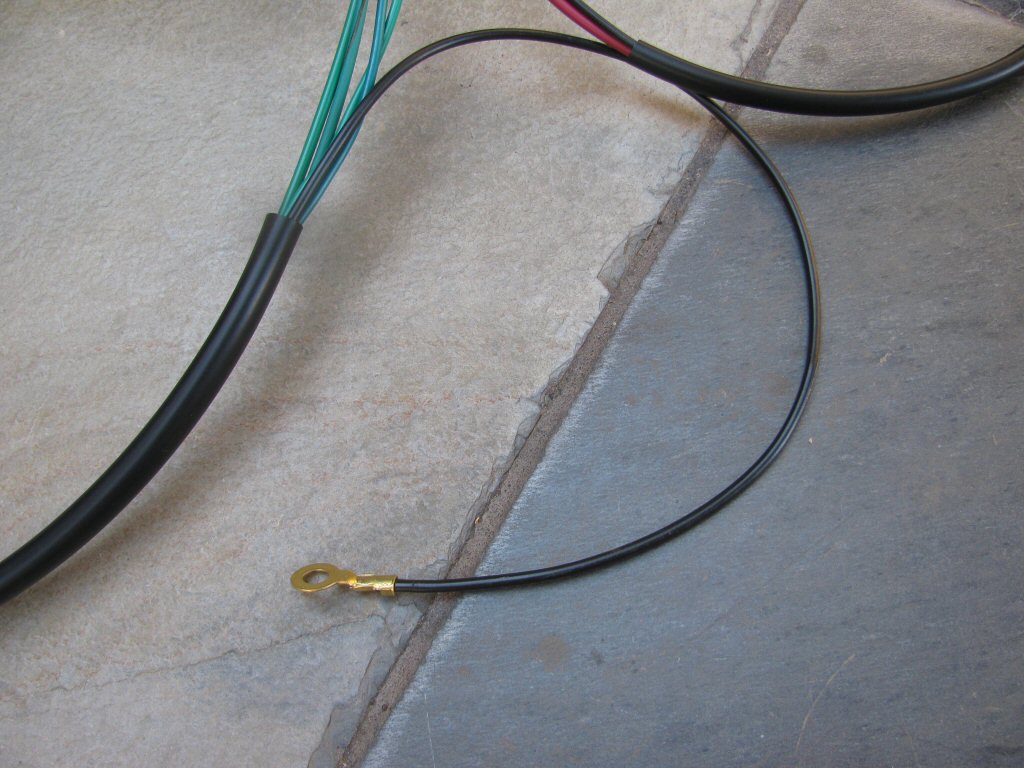
Photo courtesy of Gregory Bender.
- Connect the wires to the starter solenoid as original (see instructions).

Photo courtesy of Gregory Bender.
- Connect the brown wire from the main harness.
Newer instructions applicable to any relay solution purchased on or after
Connect the brown wire from the main harness into the 2 connection
I
splitter / quick connector.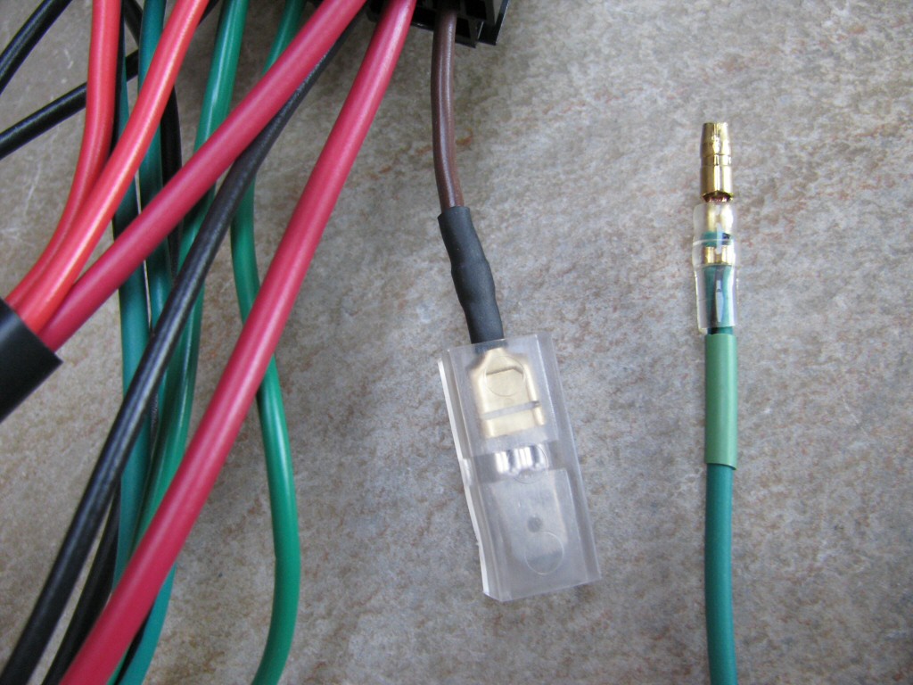
Photo courtesy of Gregory Bender.
Older instructions applicable to any relay solution purchased before
You will note that one of the relay sockets has a rubber band looped through it...
If you purchased your main harness from me at the same time that you purchased this relay harness, then your main harness will likewise have a rubber band wrapped around the end of a brown wire. These were intentionally left unassembled to make layout and routing of the wiring harnesses simpler and easier.
If you did not purchase a main harness and relay harness from me at the same time, then you will need to identify the brown wire in your existing main harness. This brown wire connects the starter button to the starter relay (or directly to the starter solenoid on some early models). Cut the terminal from the end of the brown wire and crimp on the new terminal included in the packaging I sent.
Once you have everything routed, you will need to remove the rubber bands and insert the terminal into the slot identified by the rubber band. The relay socket is
keyed
with a relief for the protruding prong on the brown wire terminal. Insert the brown wire terminal fully into the relay socket until you hear/feel it click in place. Please note: It is much easier to insert the terminal than it is to remove it later. Save yourself a headache and wait until the very end to insert it.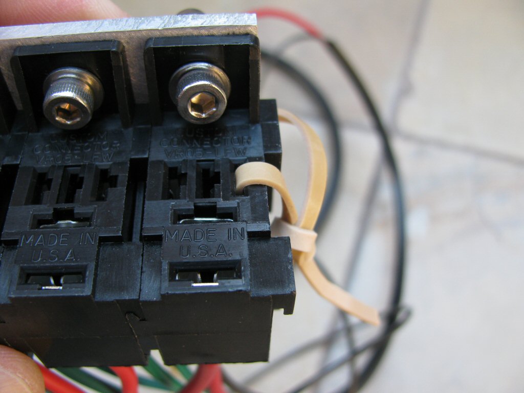
Photo courtesy of Gregory Bender.
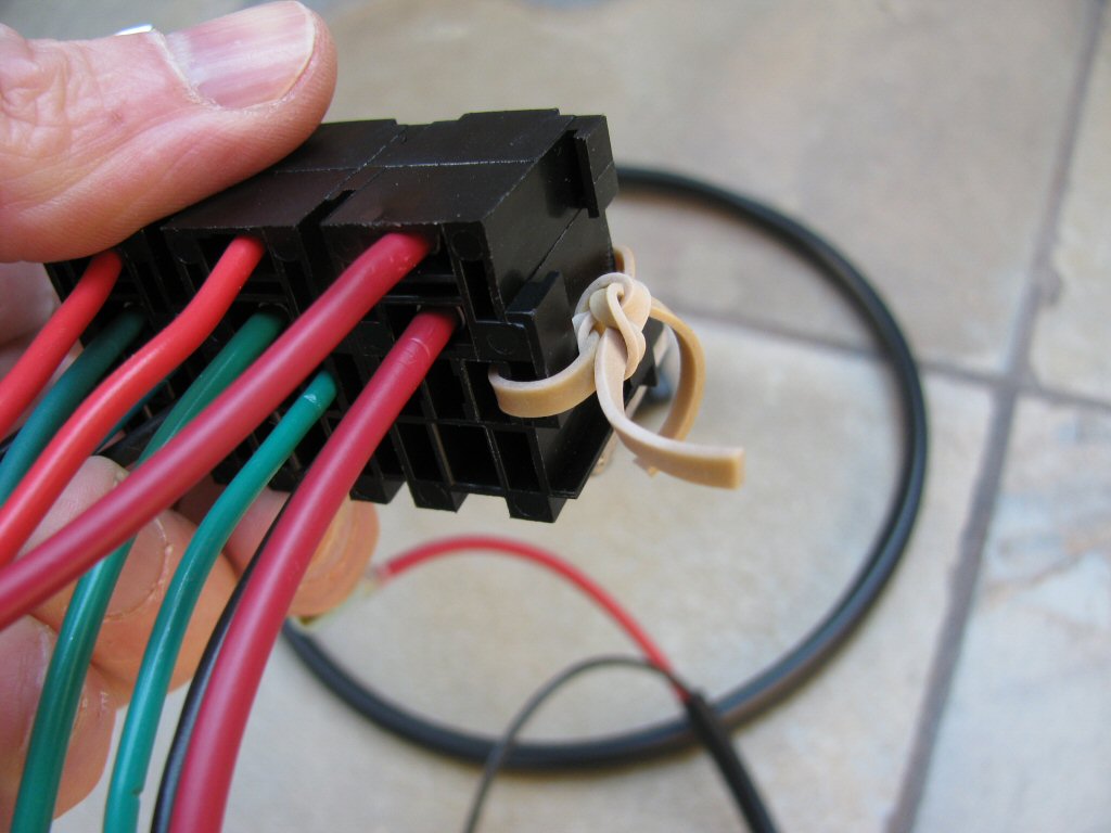
Photo courtesy of Gregory Bender.
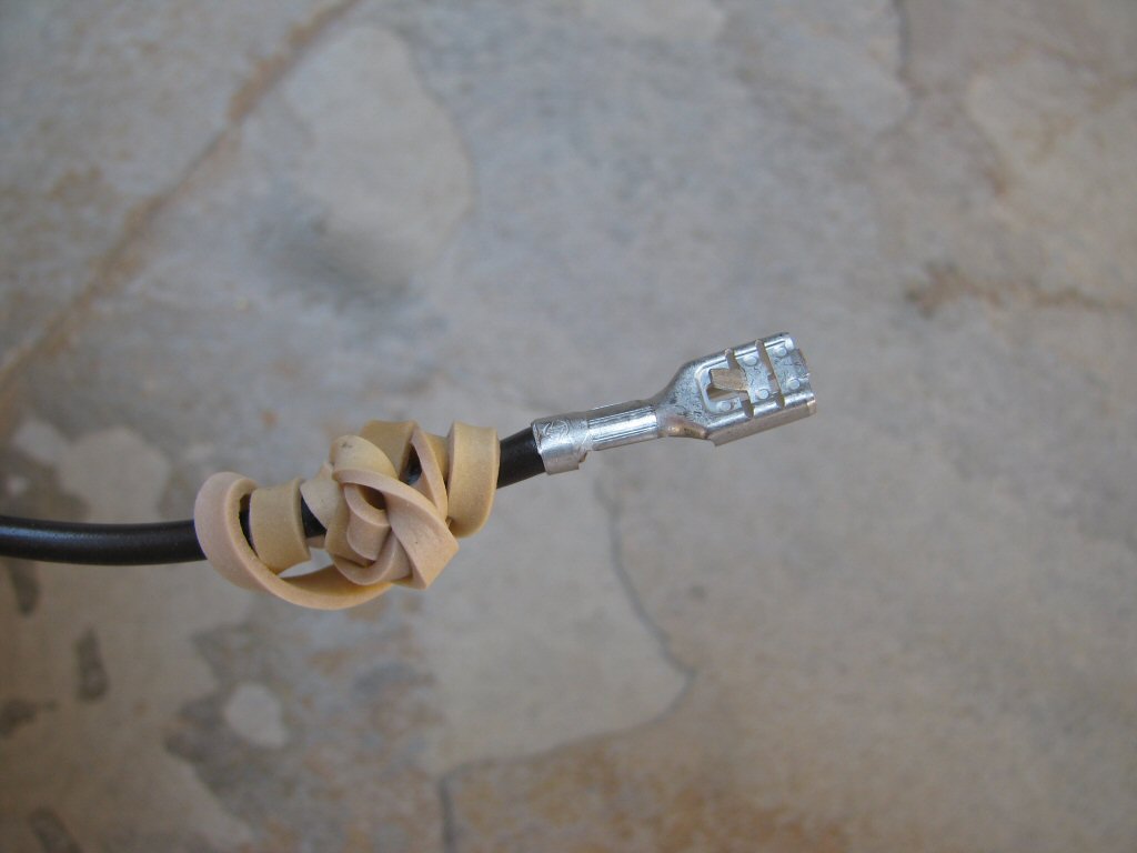
Photo courtesy of Gregory Bender.
- The only thing left to do is to plug a relay into each socket.