Turn signals (civilian)
Created:
Updated:
Turn signal sub-harness
Applicable to these part numbers:
Routing
- Route the turn signal harness such that it follows the main harness; continuing under the rear fender to the tail light.
- The 3 connection female spade connectors should be located under the fuel tank in the space provided by the frame.
- Route the gray/black wire up into the headlight bucket.
Inside the headlight bucket
- The gray/black wire with the 4 mm male bullet terminal is plugged into the bottom of the fuse block: into receptacle three (count from the left, as when facing the headlight bucket).
Under the fuel tank
- The white/black wire with the 6.3 mm female spade terminal is connected to the 3 connection female spade connector distributing current to the right turn signal circuit.
- The yellow/black wire with the 6.3 mm female spade terminal is connected to the 3 connection female spade connector distributing current to the left turn signal circuit.
- The purple wire with the 4 mm female bullet terminal is connected to the purple wire with the 4 mm male bullet terminal from the right handlebar switch.
At the battery tray
- The gray/black wire with the 6.3 mm female spade terminal is connected to the positive terminal (
X
or+
) on the flasher. - The purple wire with the 6.3 mm female spade terminal is connected to the load terminal (
L
) on the flasher.
At the tail light
- The white/black wire with the 4 mm male bullet terminal is connected to the right rear turn signal.
- The yellow/black wire with the 4 mm male bullet terminal is connected to the left rear turn signal.
Right handlebar switch
Applicable to these part numbers:
Warning:
It is very easy to destroy original or aftermarket switches when using a conventional soldering iron. Even if you know exactly what you are doing and are very experienced with soldering procedures, the switches can very easily be rendered useless. Rather than using solder, I strongly recommend the following:
- Use a conductive epoxy to secure the wires to the switch. Most epoxies, including JB Weld, do not conduct electricity. MG Chemicals makes a conductive epoxy that I've used with excellent results (part number 8331D). Atom Adehesives AA-PROD 123 is a less expensive epoxy that Charlie Mullendore of Antietam Classic Cycle reports works well. Nick Rossi contacted Atom Adhesives directly and found that AA-Duct 902 is the
most conductive epoxy
and that AA-Duct 916 ismore suitable for motorcycle applications as it is flexible once cured and will be more resistant to vibration
. Nick prefers the AA-Duct 916 (available from Amazon).
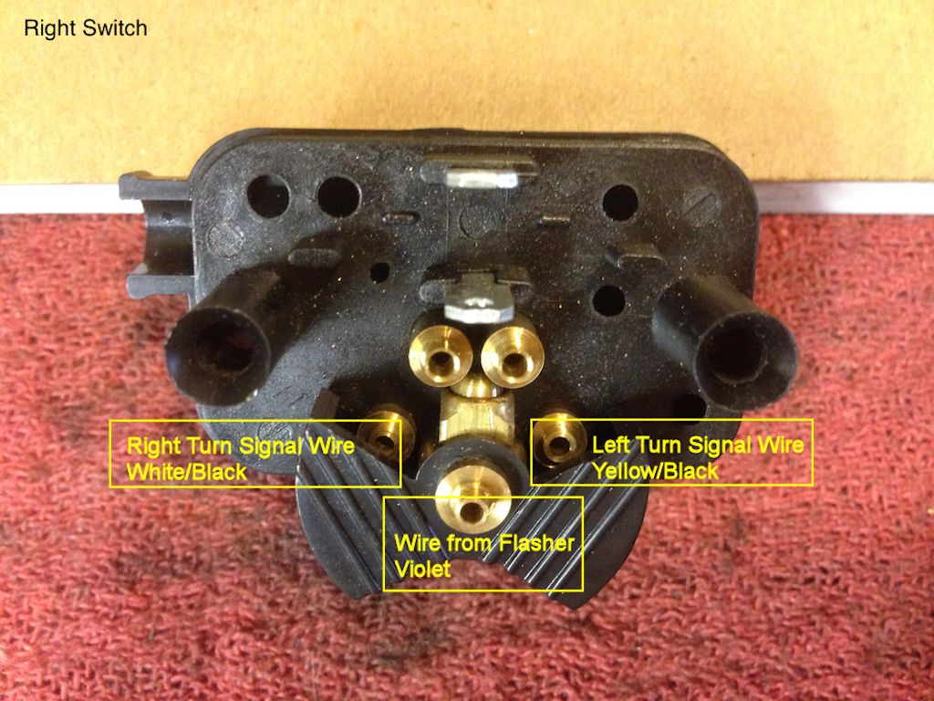
Photo courtesy of Stephen Gonzales.
The wires from the right handlebar switch (purple, white/black, yellow/black) are routed along the handlebar, down past the right side of the steering neck, to under the fuel tank in the space provided by the frame.
- The white/black wire with the 6.3 mm female spade terminal is connected to the 3 connection female spade connector distributing current to the right turn signal circuit.
- The yellow/black wire with the 6.3 mm female spade terminal is connected to the 3 connection female spade connector distributing current to the left turn signal circuit.
- The purple wire with the 4 mm male bullet terminal is connected to the purple wire with the 4 mm female bullet terminal from the turn signal sub-harness.