2010 June 19: Engine assembly
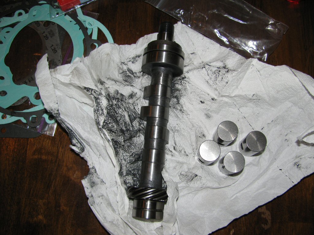
Reground cam and resurfaced tappets.
Photo courtesy of Gregory Bender.
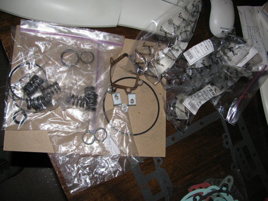
Bunch of new parts, etc.
Photo courtesy of Gregory Bender.
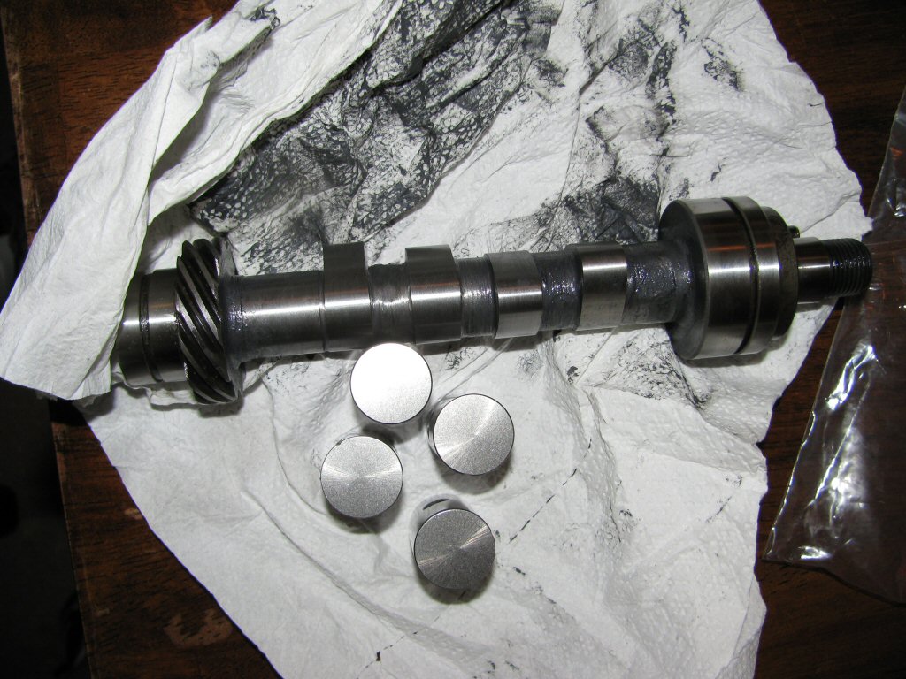
Another shot of the cam and tappets.
Photo courtesy of Gregory Bender.
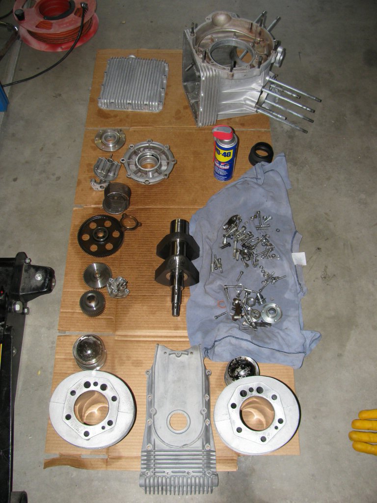
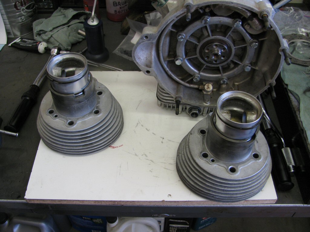
Cleaned parts ready for assembly (pistons will be further cleaned).
Photo courtesy of Gregory Bender.
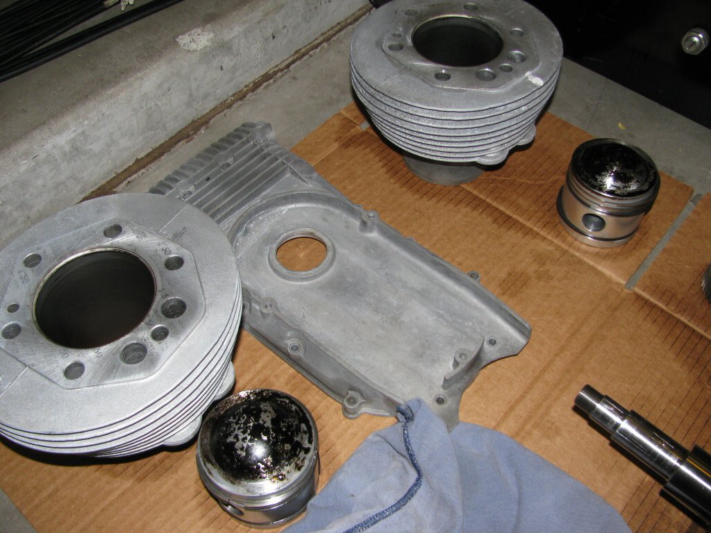
Closer shot of cleaned parts.
Photo courtesy of Gregory Bender.
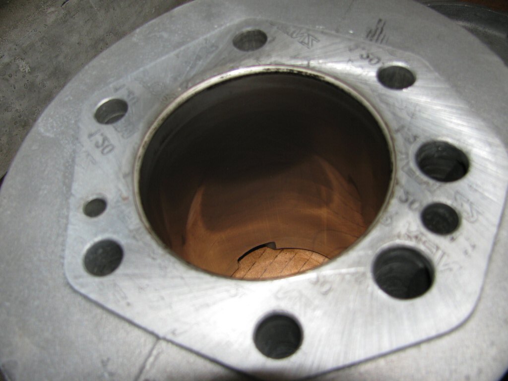
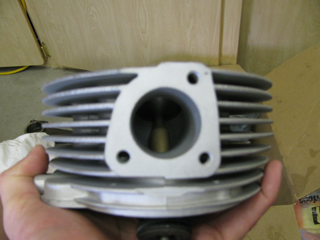
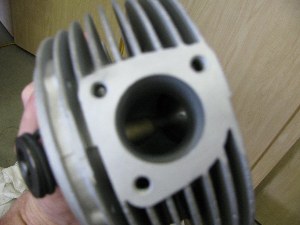
Cylinder.
Photo courtesy of Gregory Bender.
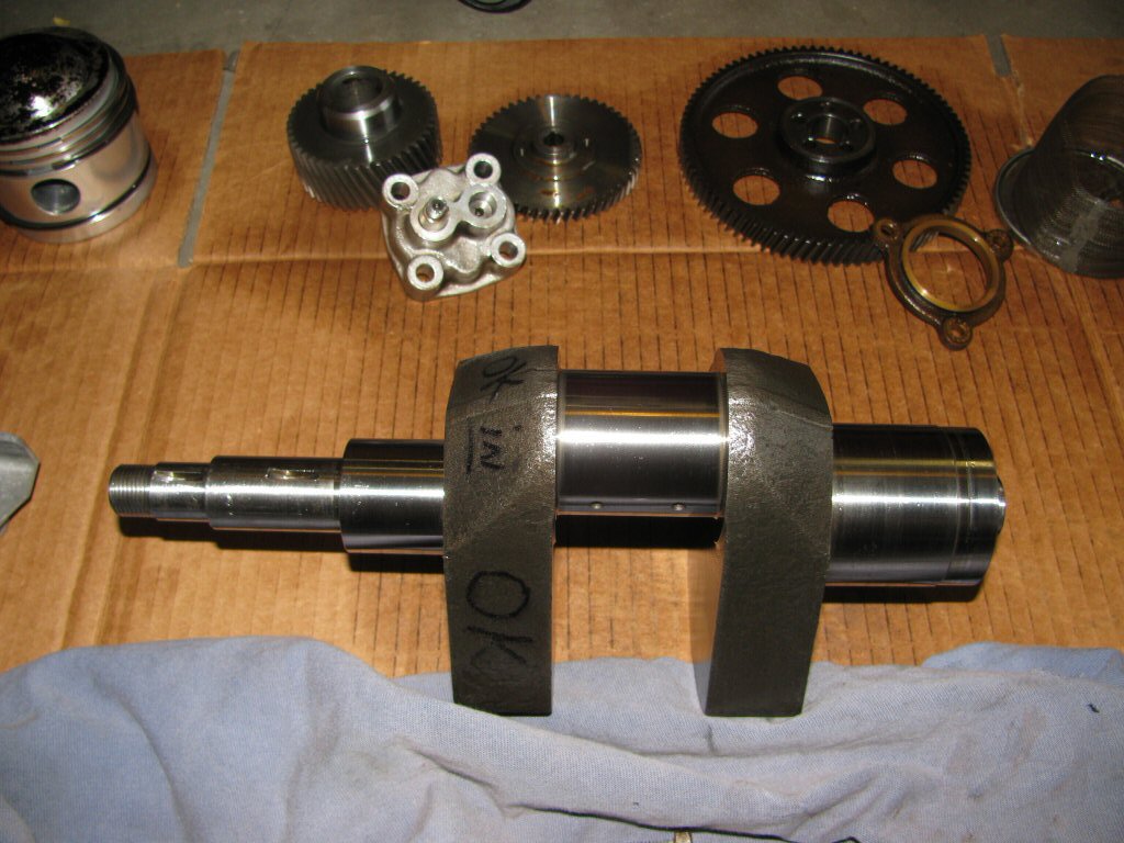
Crankshaft.
Photo courtesy of Gregory Bender.
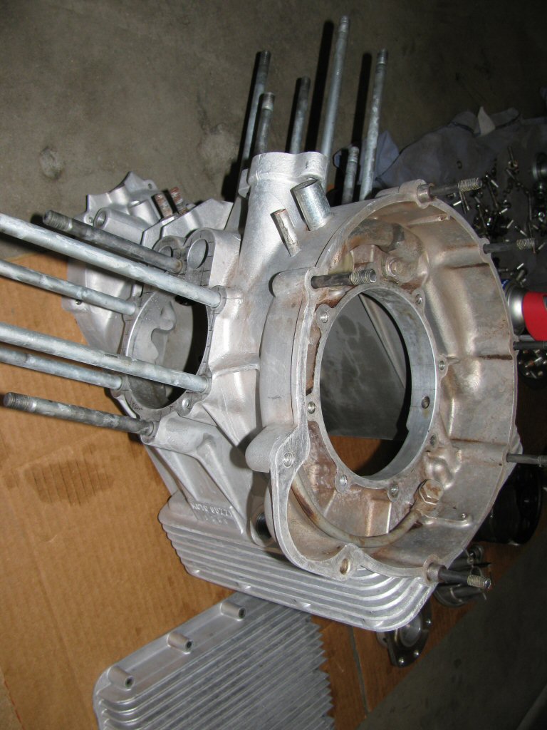
Engine case.
Photo courtesy of Gregory Bender.
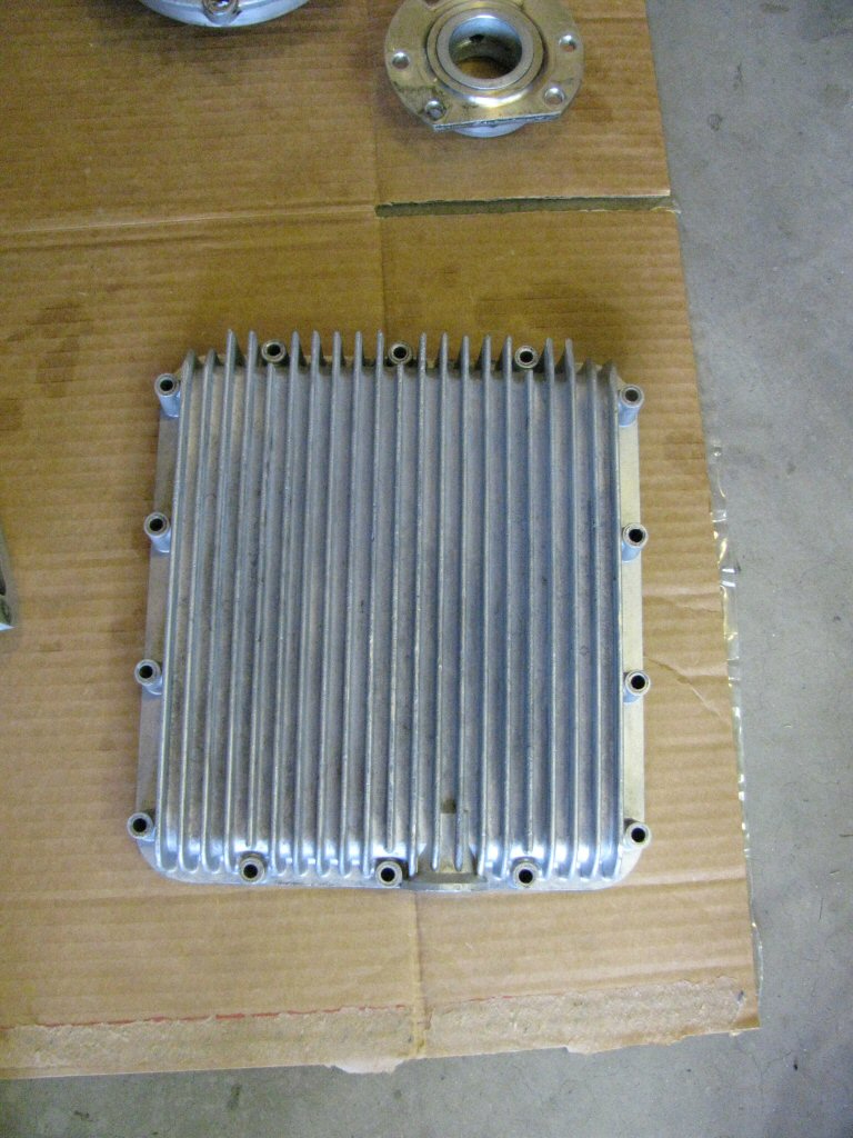
Oil pan.
Photo courtesy of Gregory Bender.
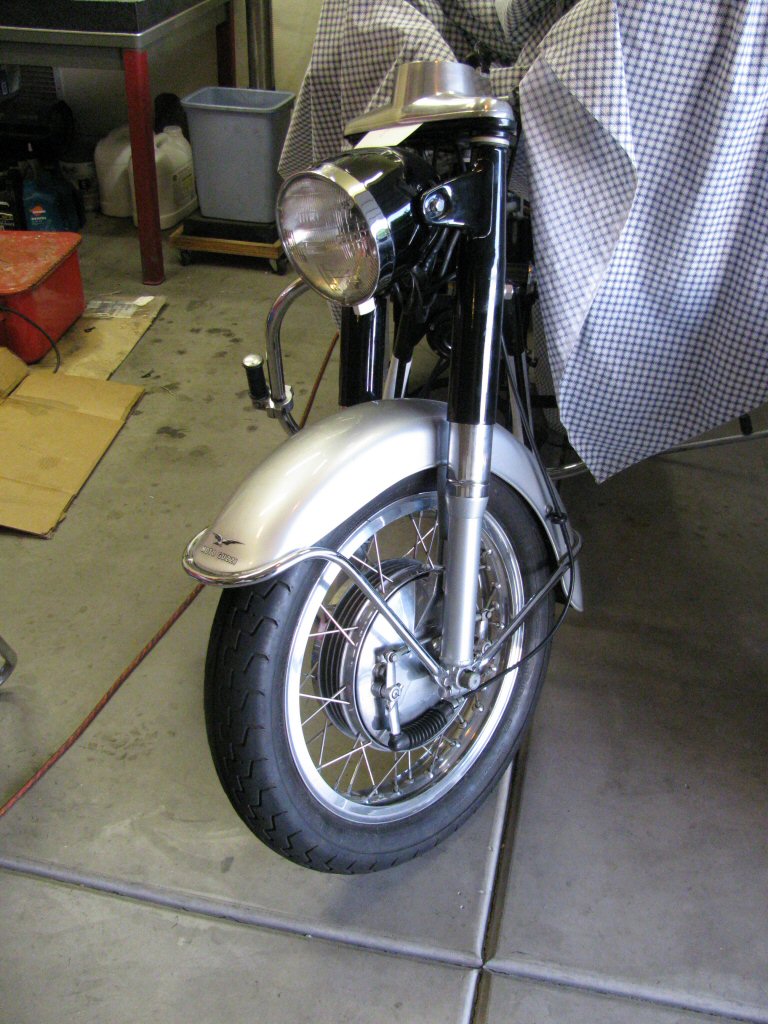
Front forks.
Photo courtesy of Gregory Bender.
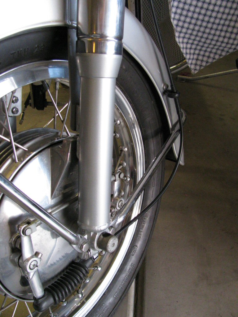
Front forks.
Photo courtesy of Gregory Bender.
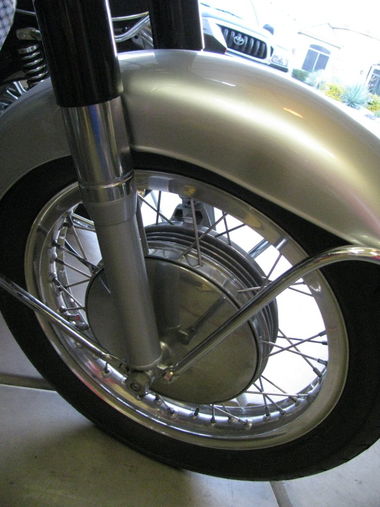
Front forks.
Photo courtesy of Gregory Bender.
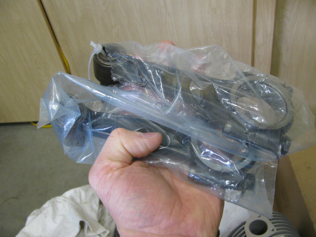
Connecting rods fresh from the machinist.
Photo courtesy of Gregory Bender.
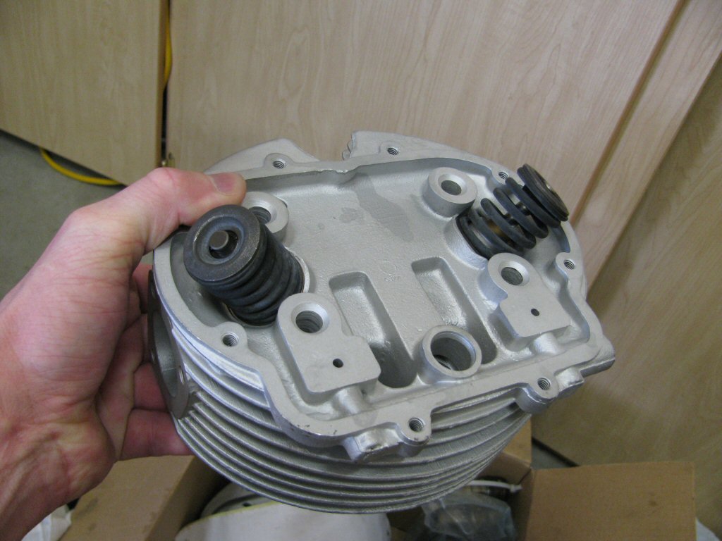
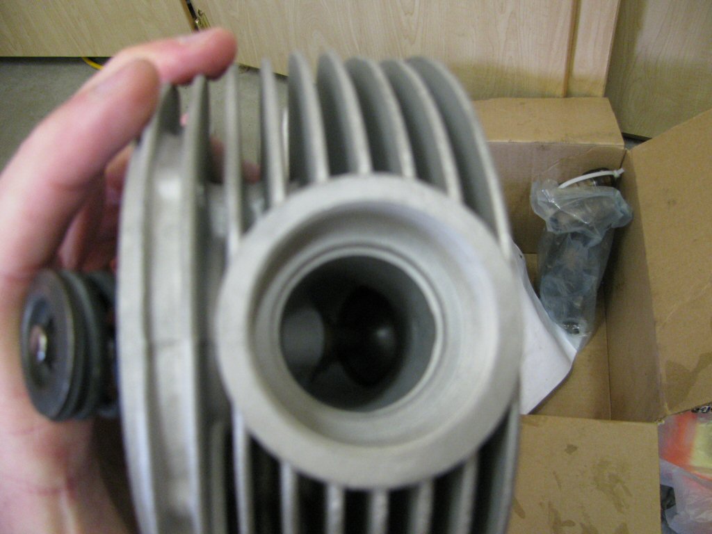
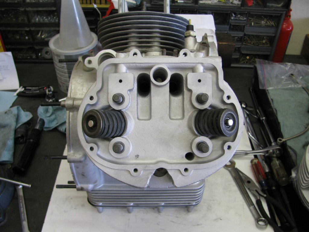
Cylinder heads fresh from the machinist.
Photo courtesy of Gregory Bender.
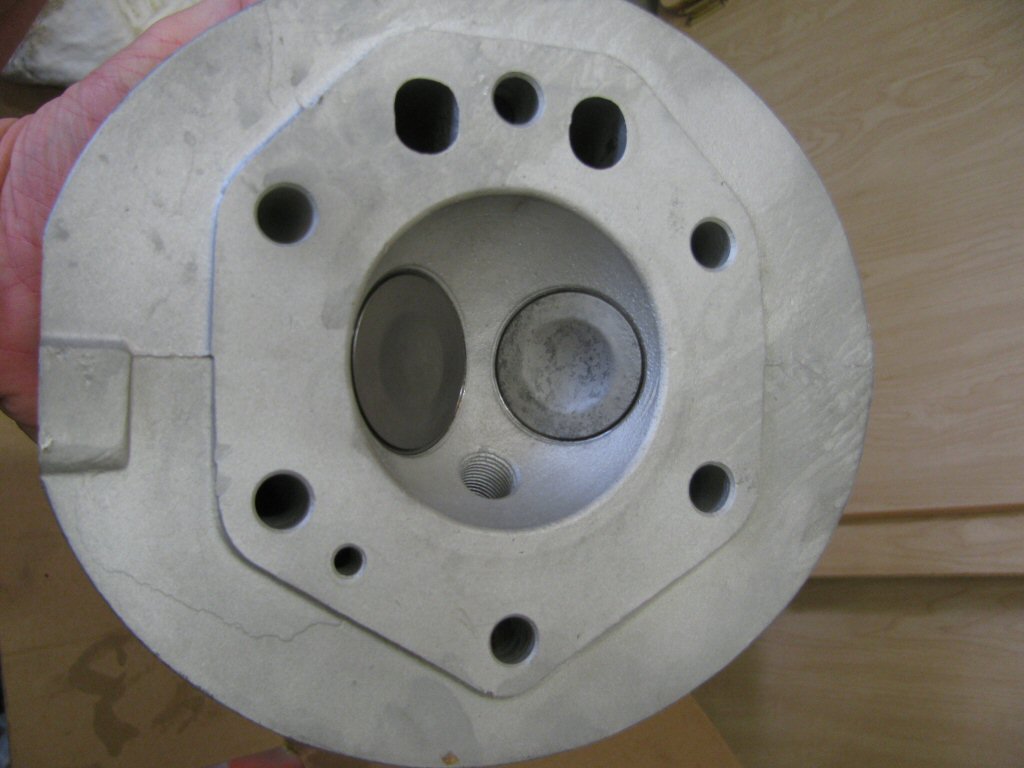
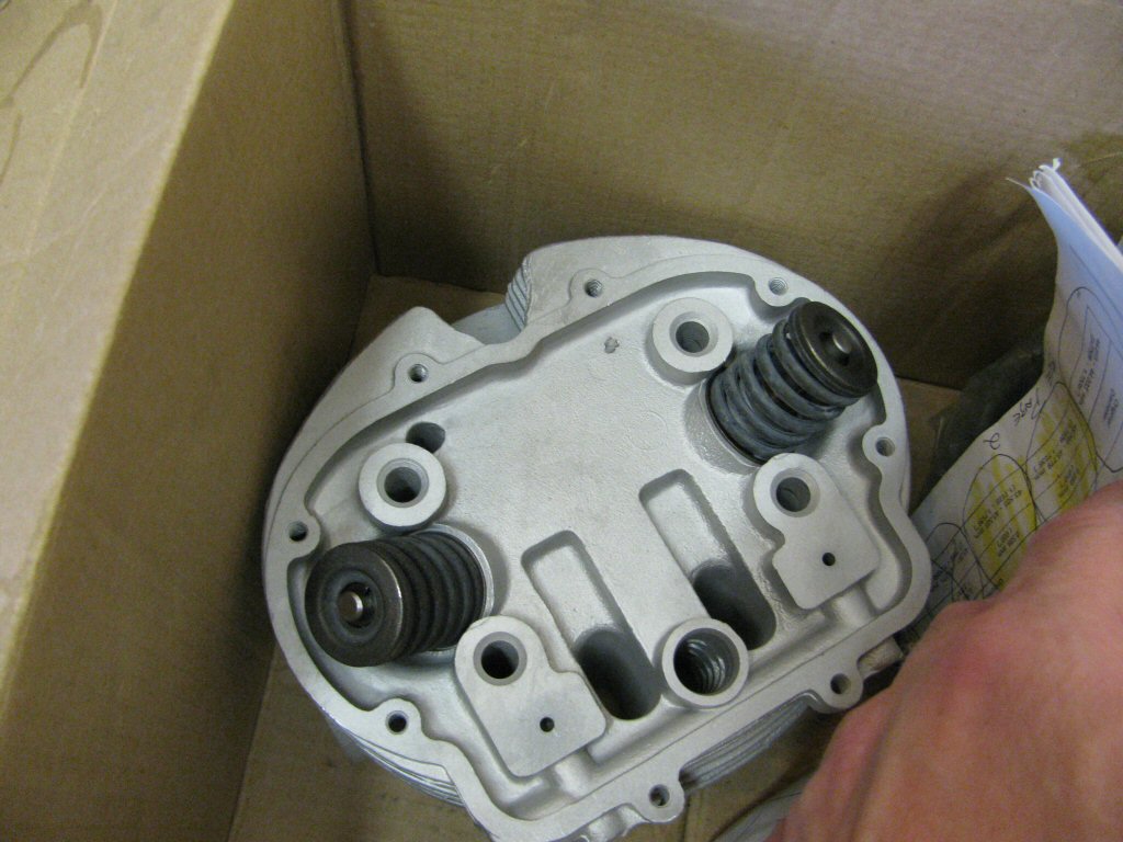
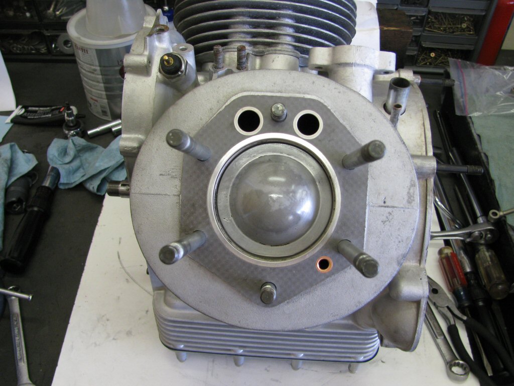
Cylinder heads fresh from the machinist.
Photo courtesy of Gregory Bender.
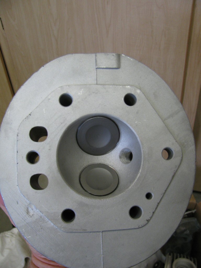
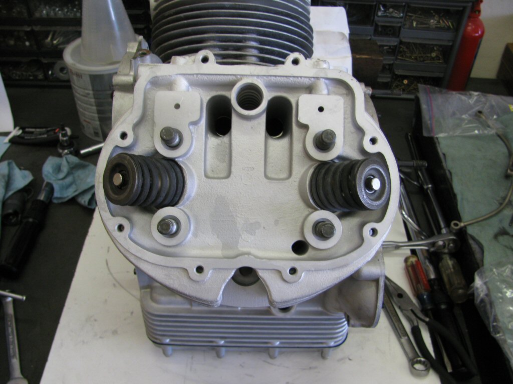
Cylinder heads fresh from the machinist.
Photo courtesy of Gregory Bender.
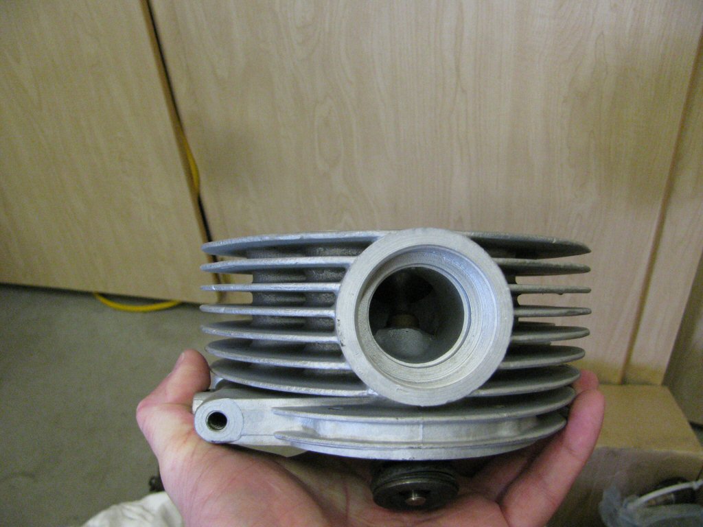
Cylinder heads fresh from the machinist.
Photo courtesy of Gregory Bender.
Cylinder heads fresh from the machinist.
Photo courtesy of Gregory Bender.
Cylinder heads fresh from the machinist.
Photo courtesy of Gregory Bender.
Cylinder heads fresh from the machinist.
Photo courtesy of Gregory Bender.
Cylinder heads fresh from the machinist.
Photo courtesy of Gregory Bender.
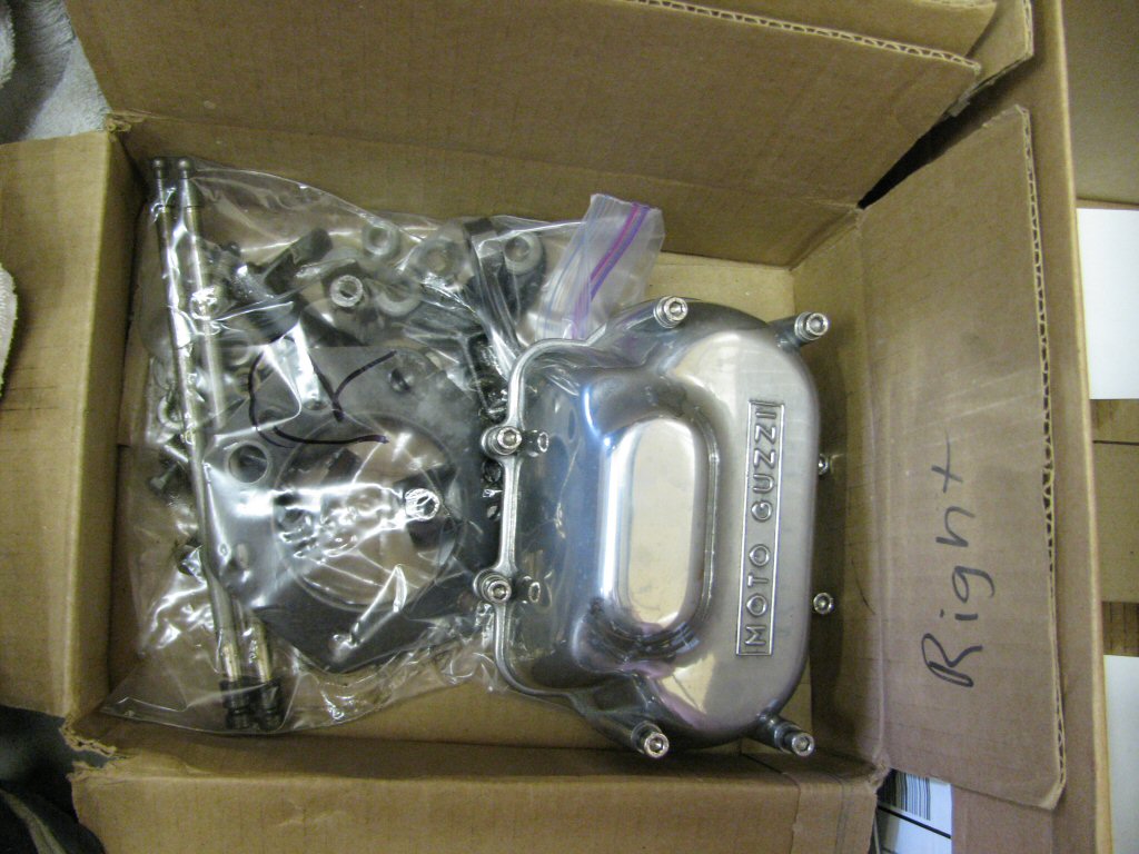
Top end components.
Photo courtesy of Gregory Bender.
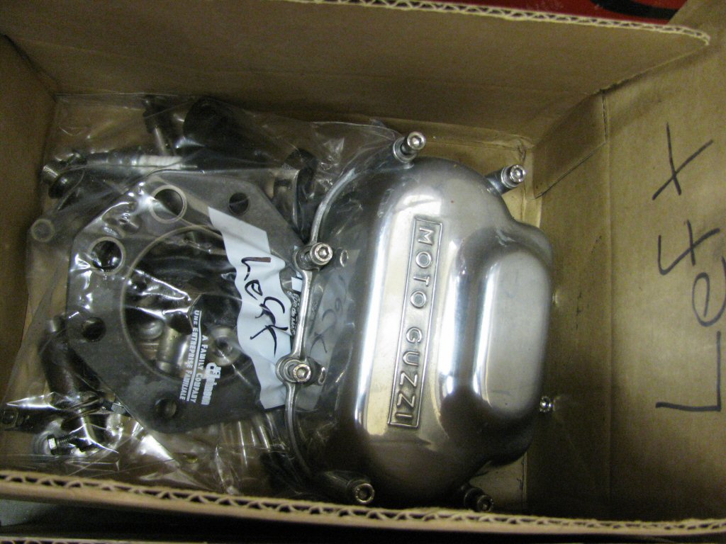
Top end components.
Photo courtesy of Gregory Bender.
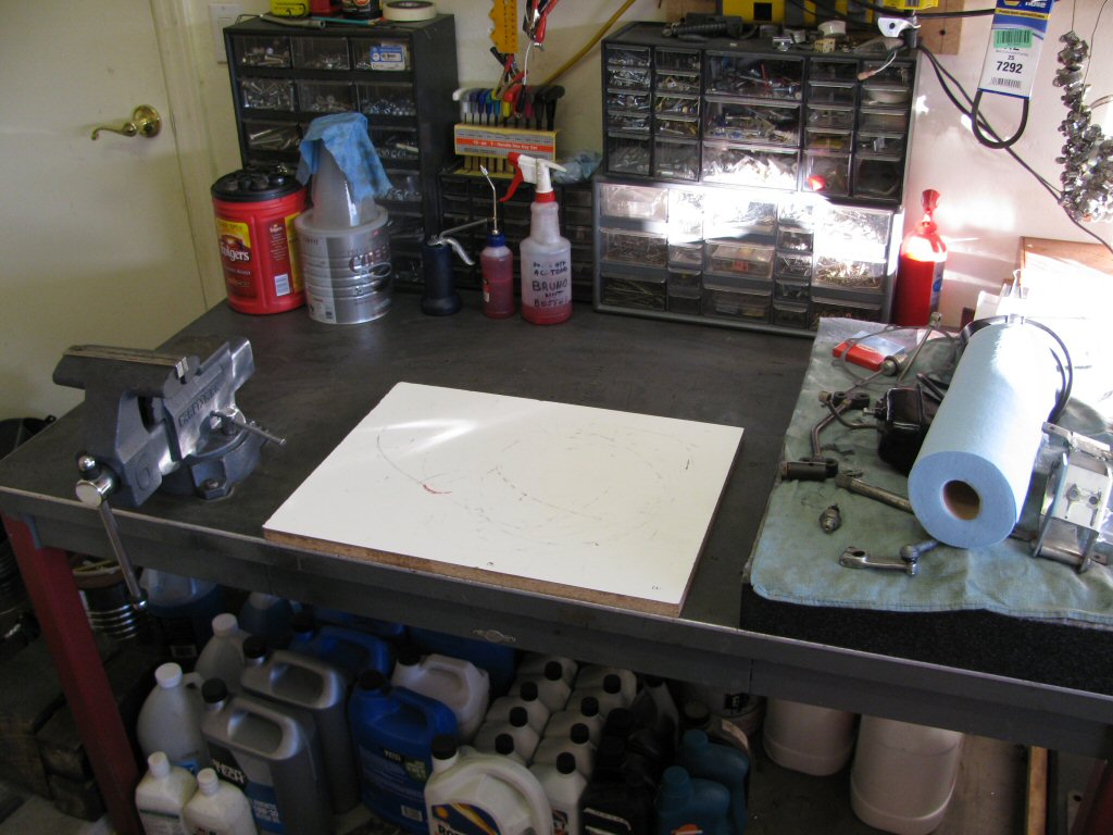
Work bench cleaned and ready to start.
Photo courtesy of Gregory Bender.
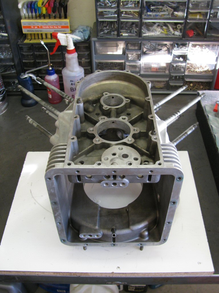
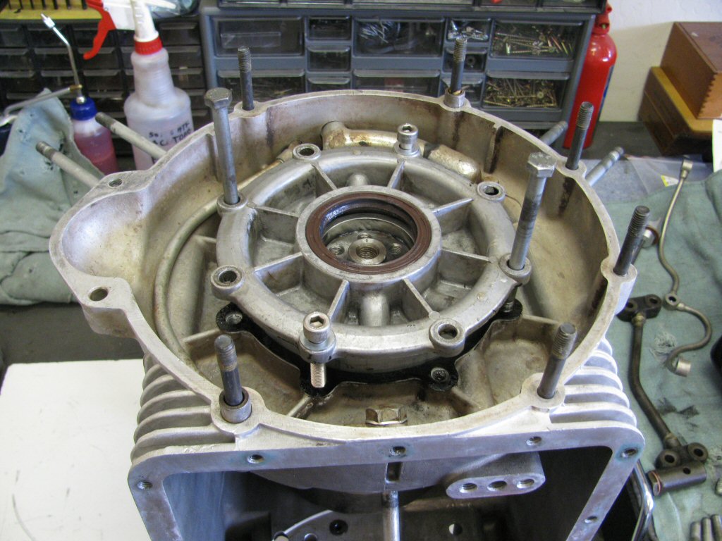
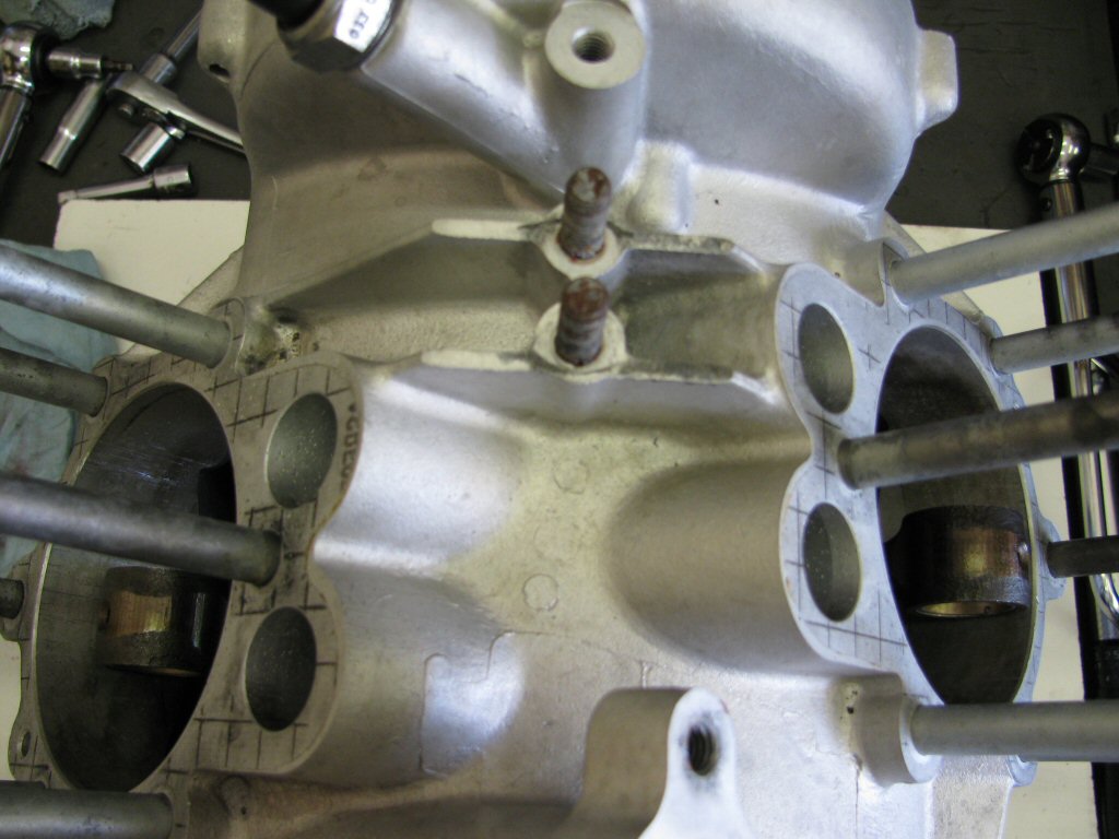
The bare case.
Photo courtesy of Gregory Bender.
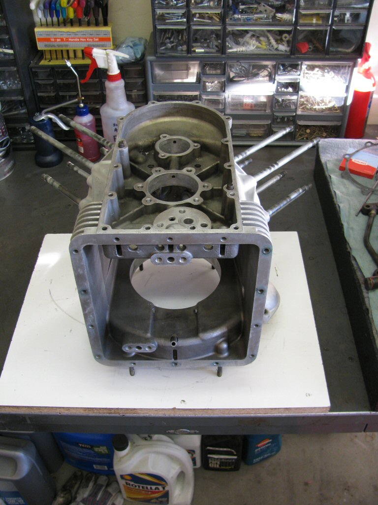
The bare case.
Photo courtesy of Gregory Bender.
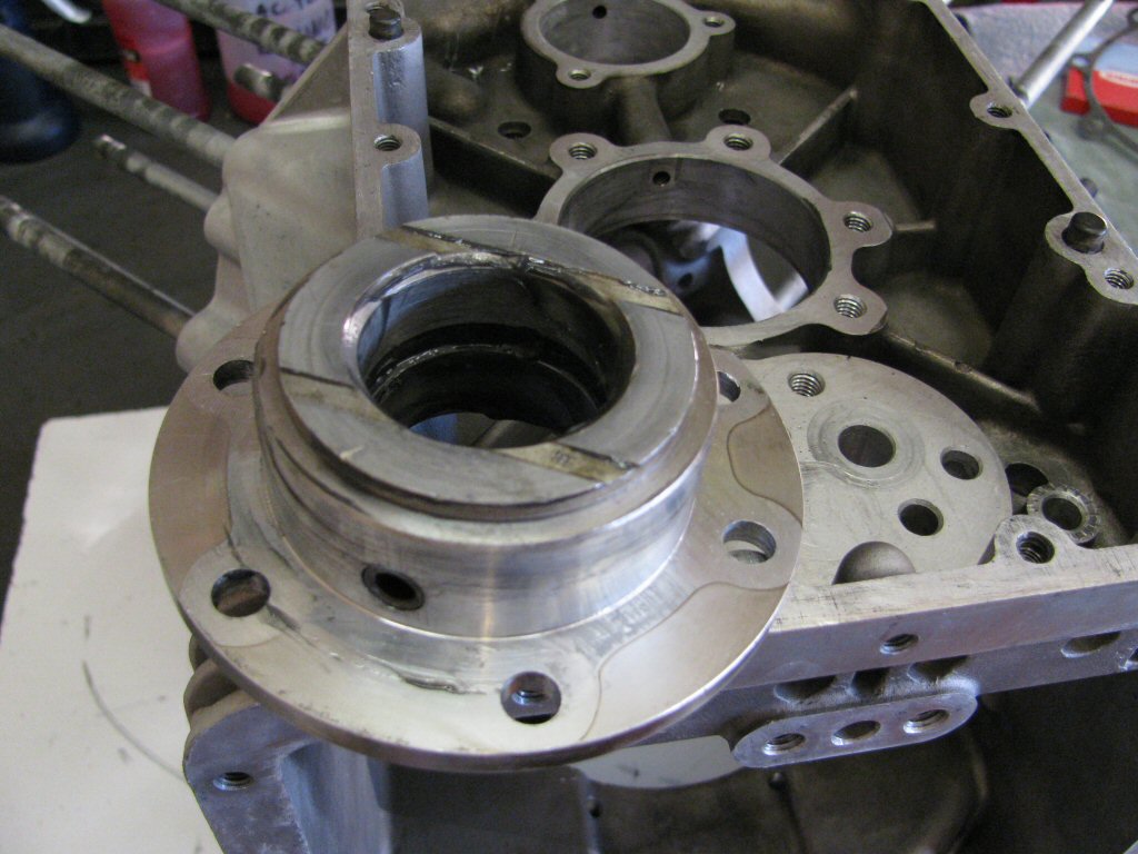
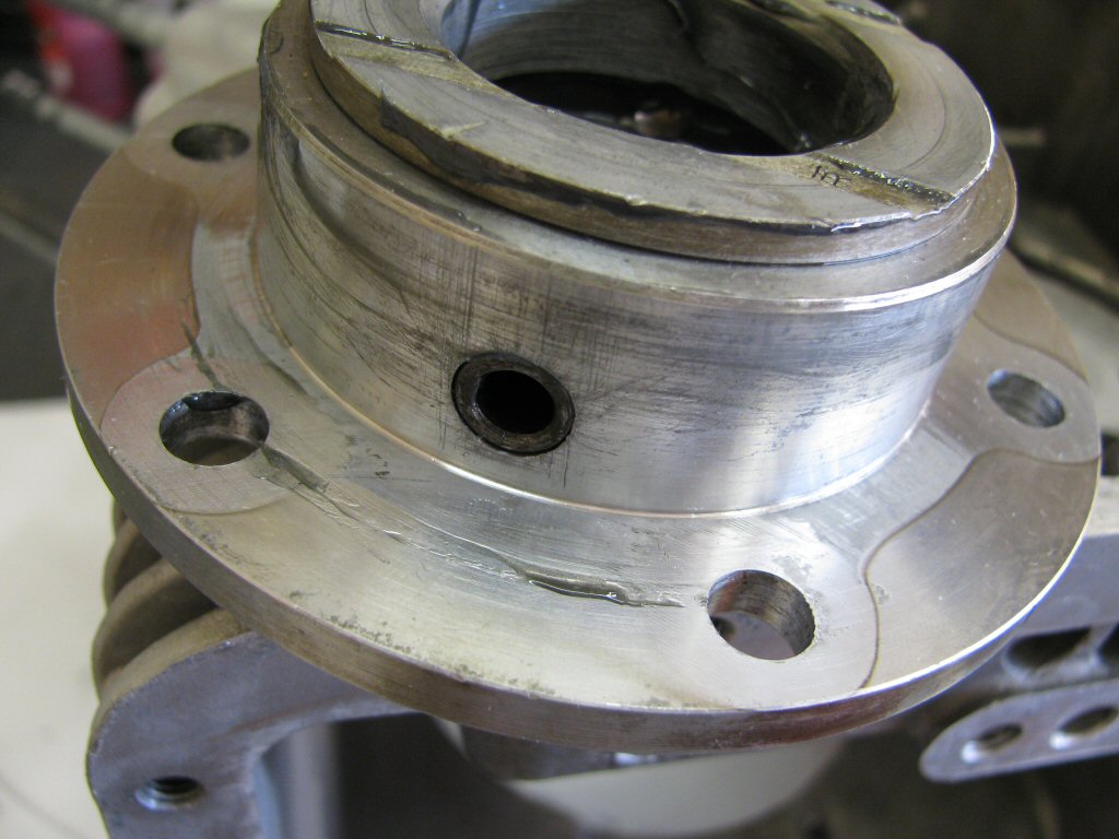
Assembly lube on front main bearing.
Photo courtesy of Gregory Bender.
Hollow oil passage in place.
Photo courtesy of Gregory Bender.
In place with new fasteners. I like to use the Schnorr washers on top of flat washers so that the Schnorr washers do not embed themselves into the soft aluminum.
Note: I no longer use Schnorr washers in this situation. I've learned that they are not the best solution for this application. Instead, I use Moto Guzzi's thick wave washer that they specify for use on the newest models.
Photo courtesy of Gregory Bender.
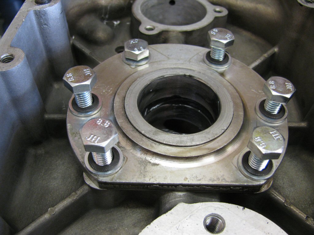
In place and torqued.
Photo courtesy of Gregory Bender.
Another shot of the same.
Photo courtesy of Gregory Bender.
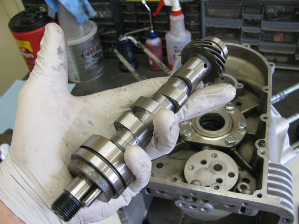
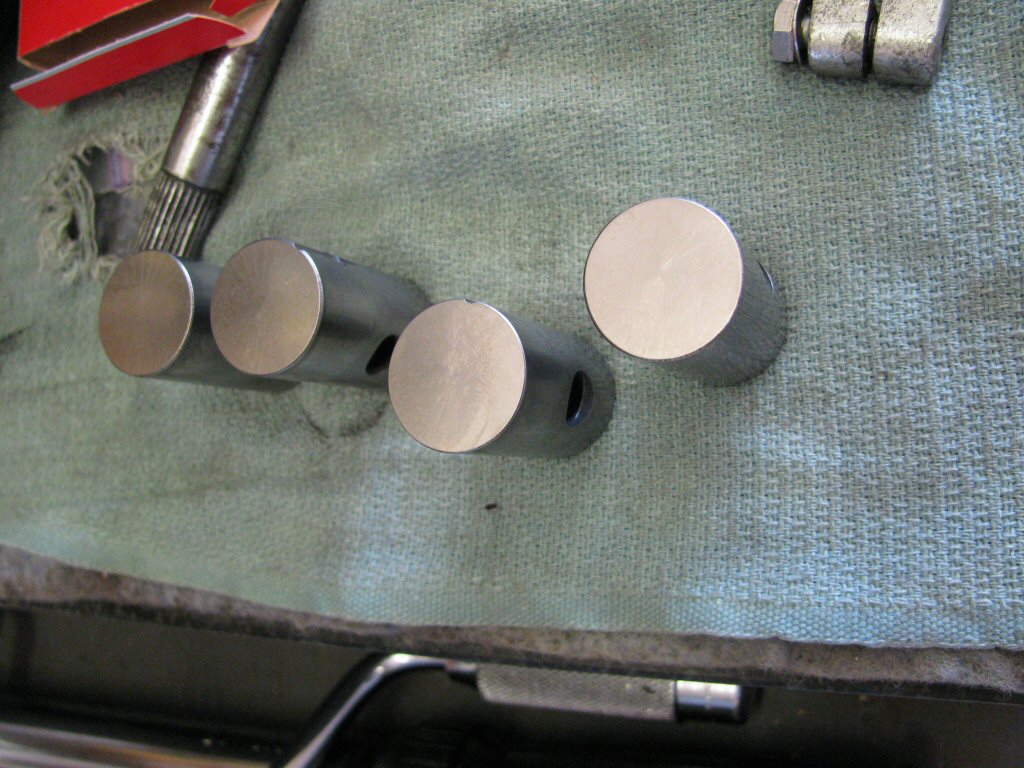
Cam cleaned and ready for install.
Photo courtesy of Gregory Bender.
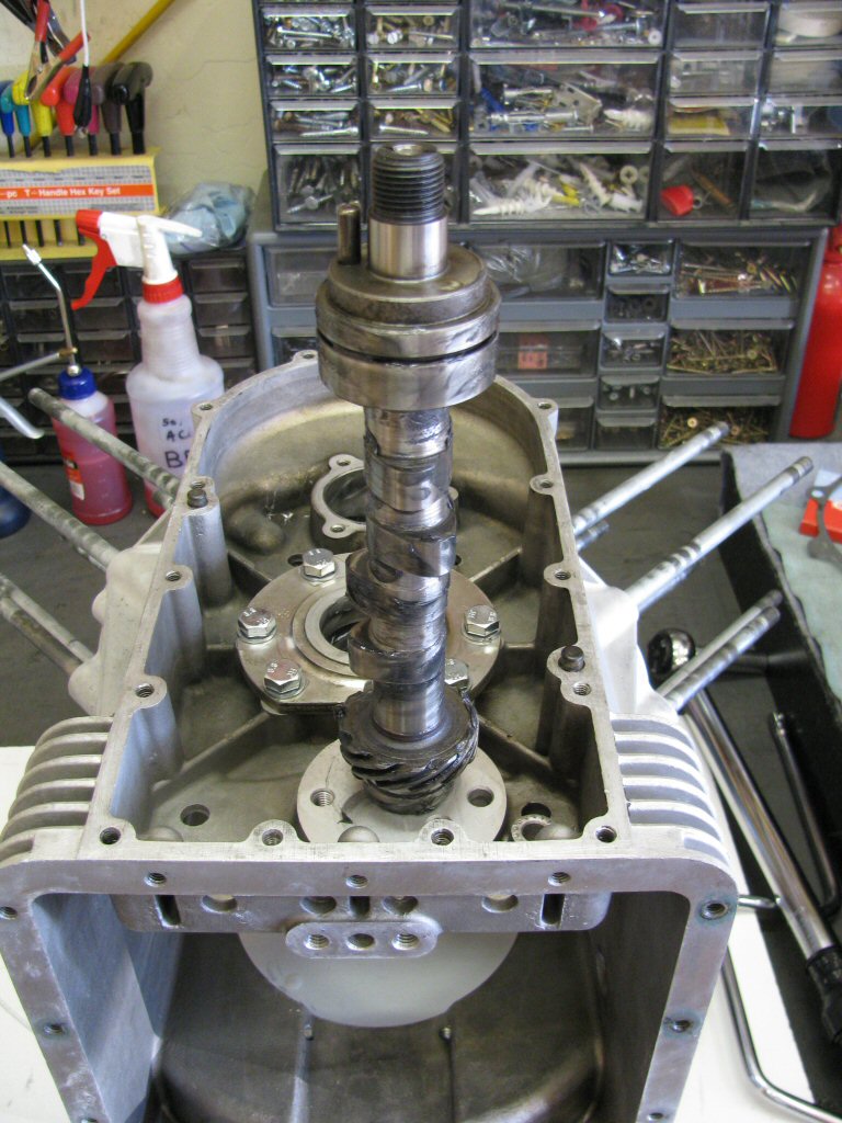
Fully slathered with assembly lube.
Photo courtesy of Gregory Bender.
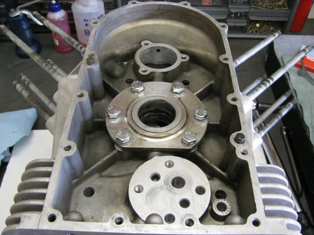
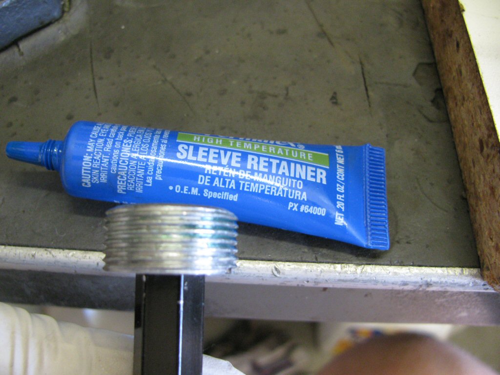
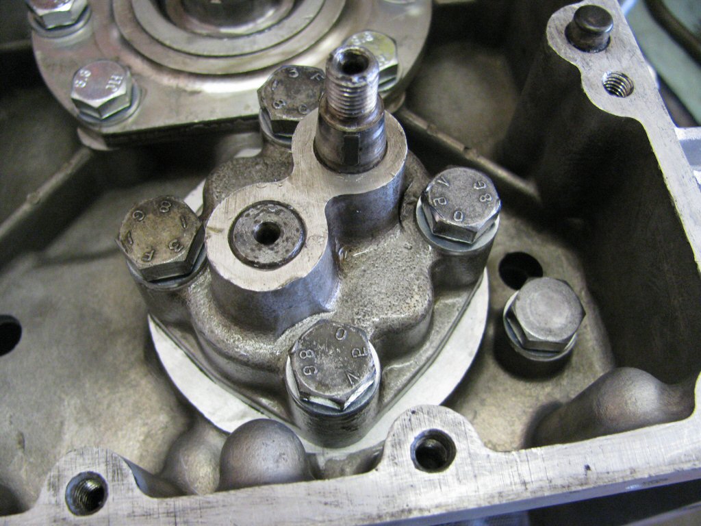
Installed with retainer torqued in place.
Photo courtesy of Gregory Bender.
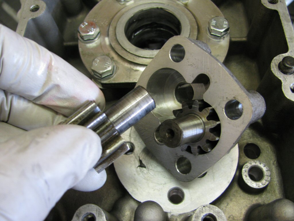
Oil pump looks pretty good.
Photo courtesy of Gregory Bender.
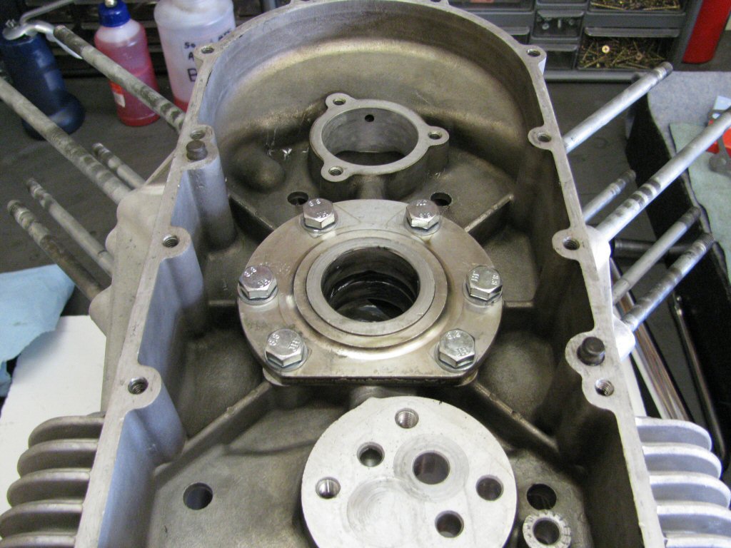
Lightly held in place for now.
Note: I no longer use Schnorr washers in this situation. I've learned that they are not the best solution for this application. Instead, I use Moto Guzzi's thick wave washer that they specify for use on the newest models.
Photo courtesy of Gregory Bender.
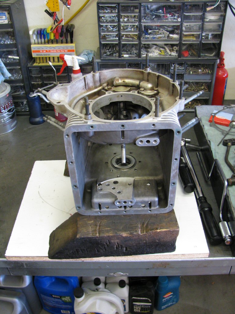
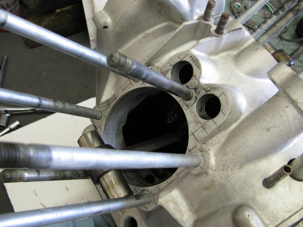
Flip the case over.
Photo courtesy of Gregory Bender.
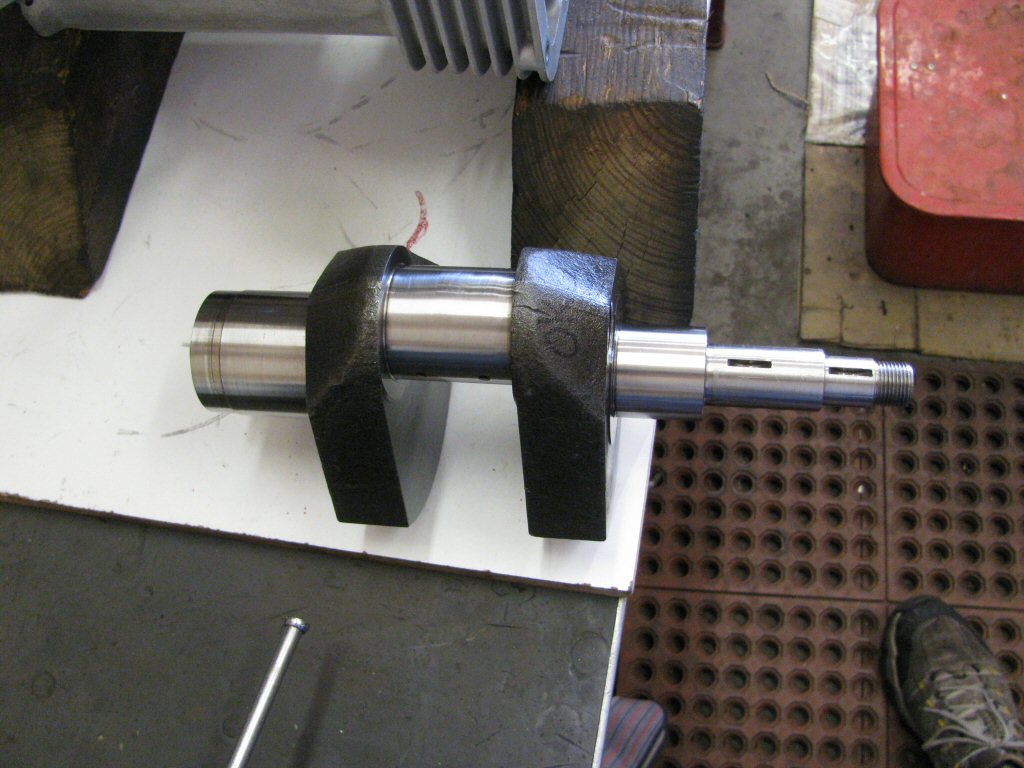
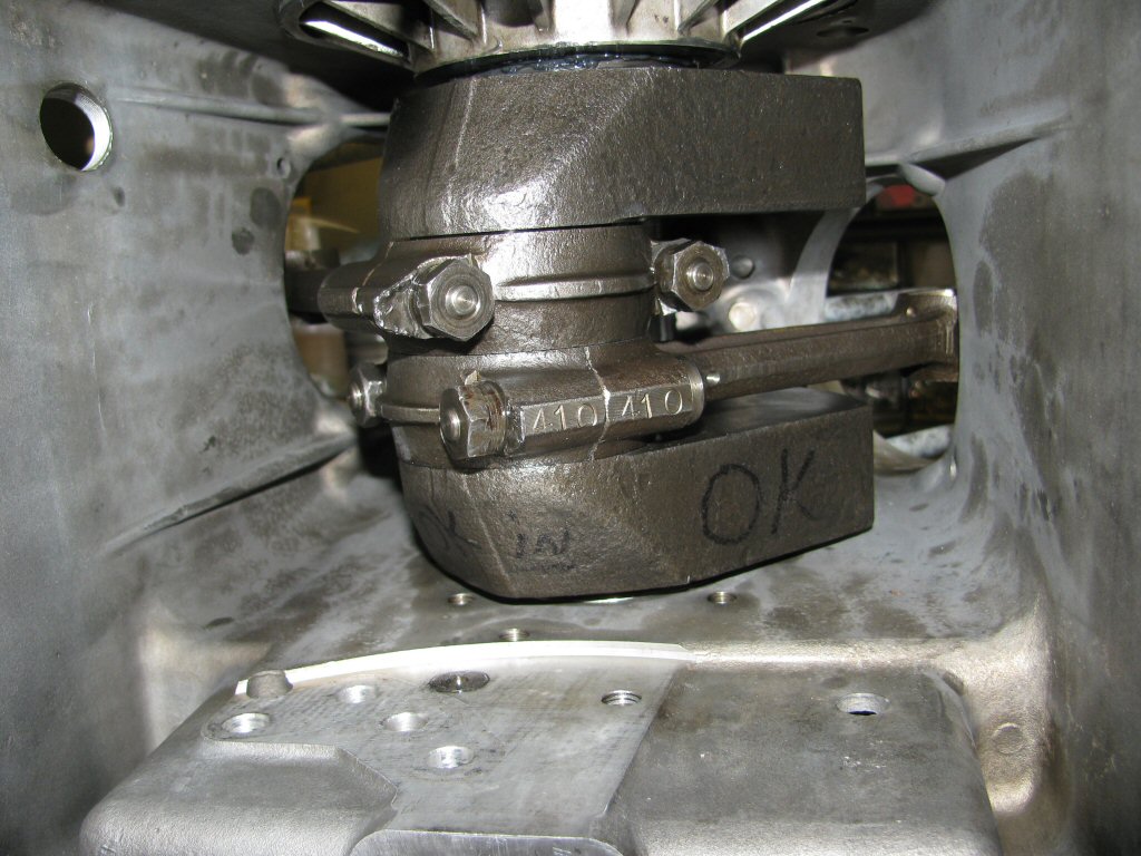
Crankshaft.
Photo courtesy of Gregory Bender.
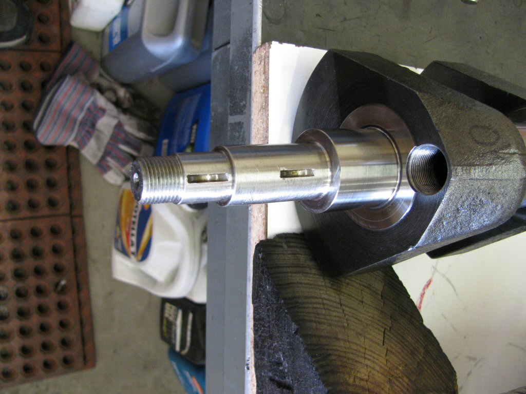
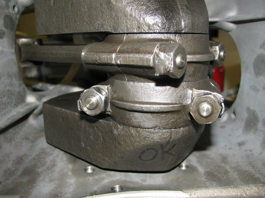
Crankshaft.
Photo courtesy of Gregory Bender.
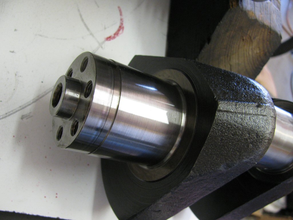
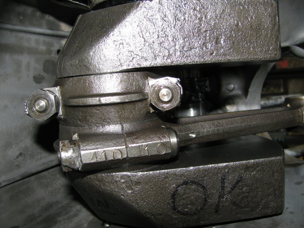
Crankshaft.
Photo courtesy of Gregory Bender.
A bit of Loctite on the sludge trap plug.
Photo courtesy of Gregory Bender.
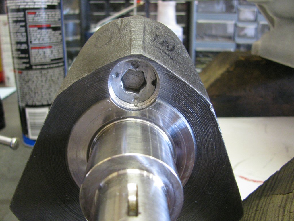
Plug in place and punched.
Photo courtesy of Gregory Bender.
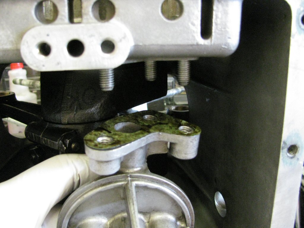
Hollow oil passage in place.
Photo courtesy of Gregory Bender.
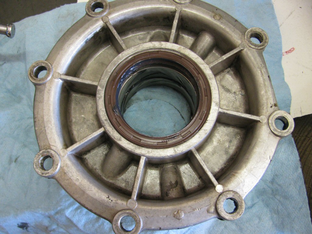
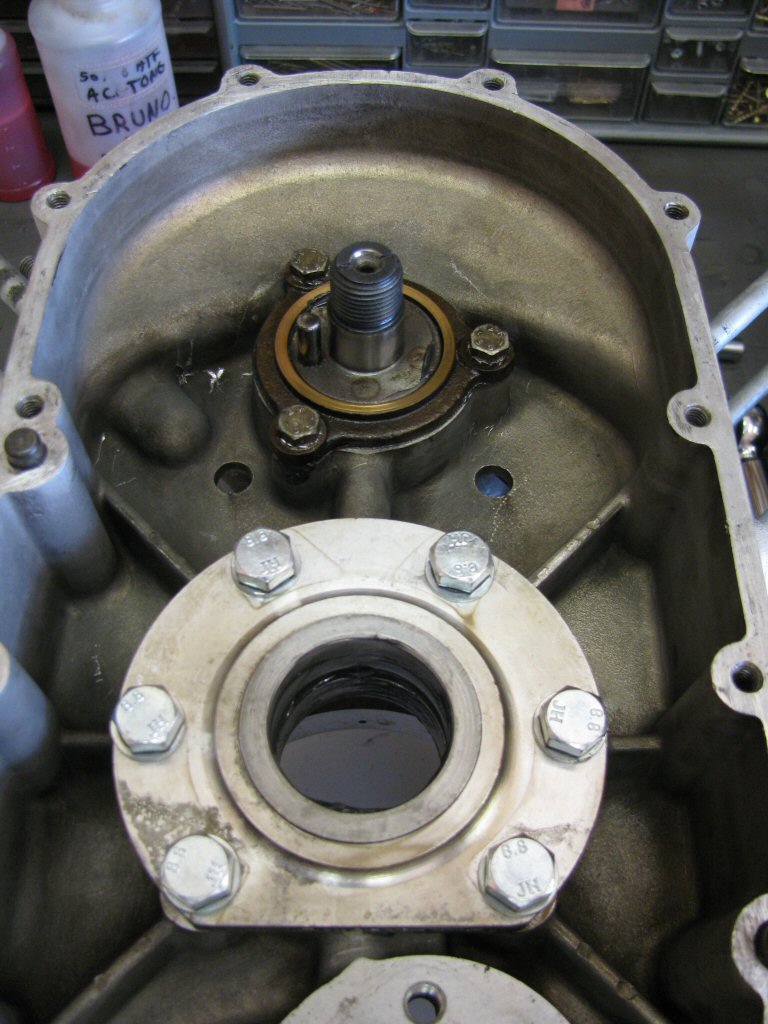
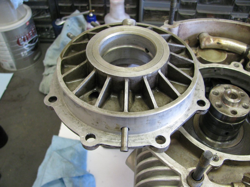
New seal installed and lubed.
Photo courtesy of Gregory Bender.
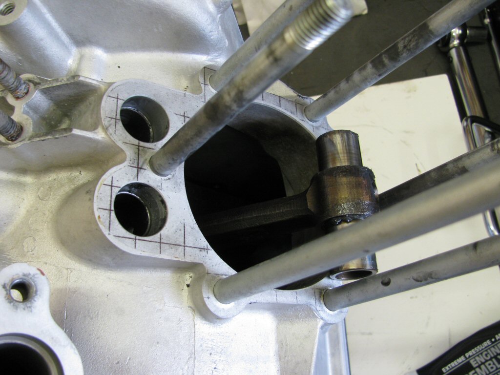
Crankshaft in place, installing rear main bearing.
Photo courtesy of Gregory Bender.
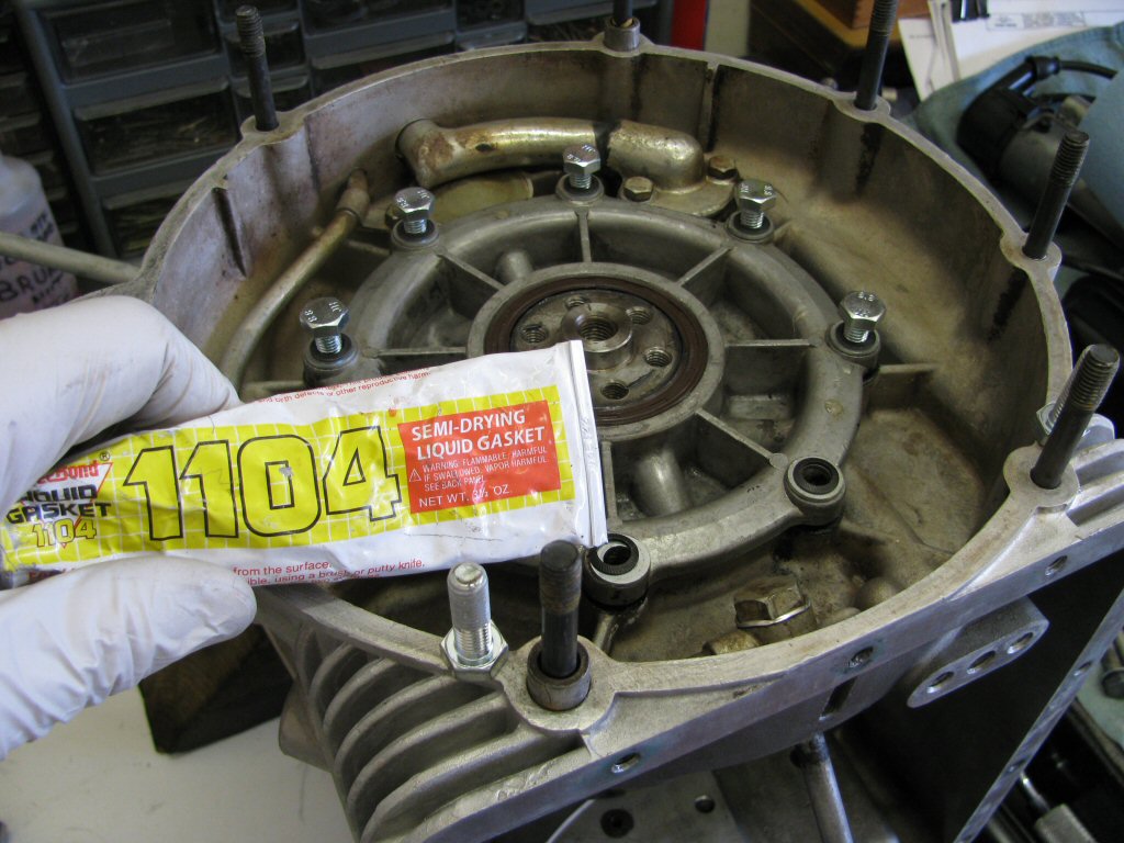
Bottom two bolts get sealant to prevent leaks.
Note: I no longer use Schnorr washers in this situation. I've learned that they are not the best solution for this application. Instead, I use Moto Guzzi's thick wave washer that they specify for use on the newest models.
Photo courtesy of Gregory Bender.
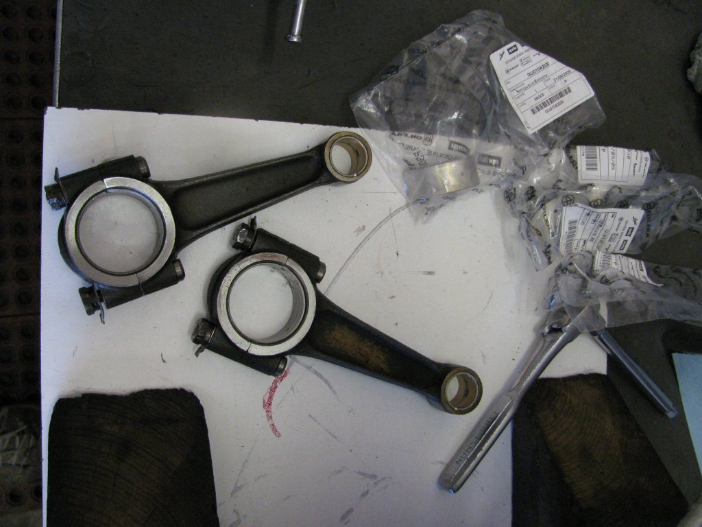
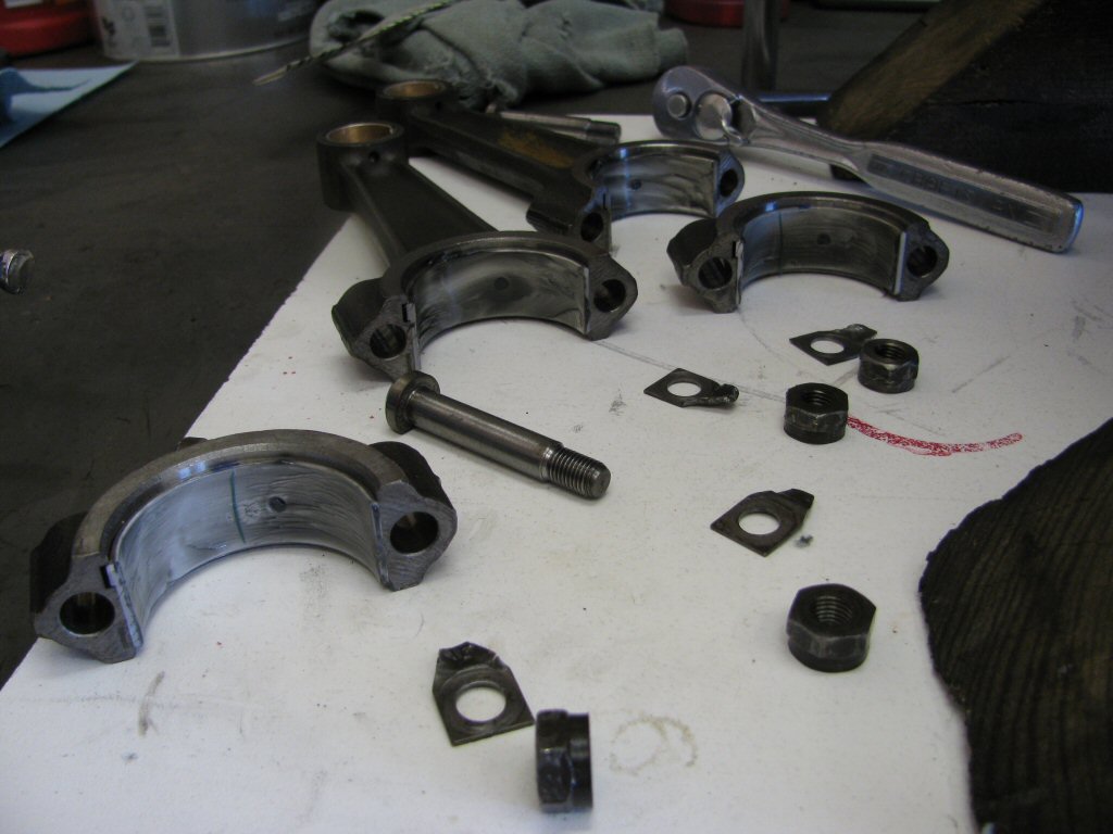
Connecting rods and plastic bags containing the new shells.
Photo courtesy of Gregory Bender.
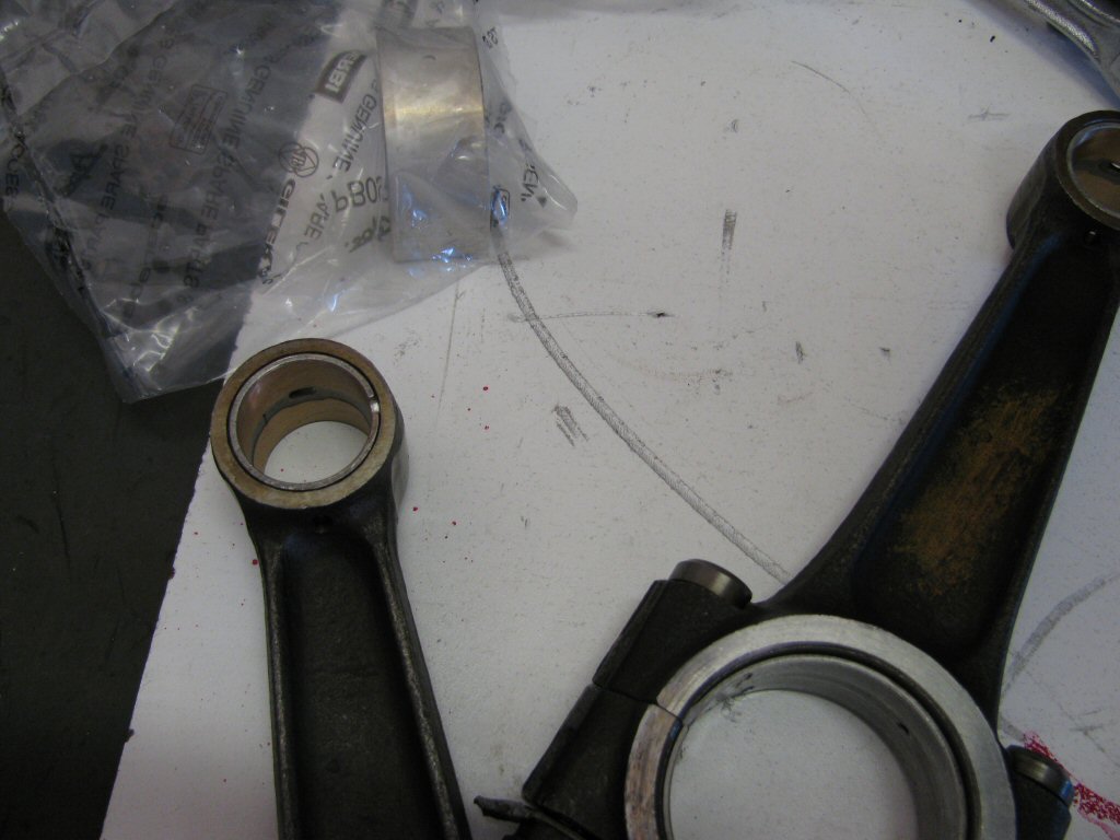
New small end bushes.
Photo courtesy of Gregory Bender.
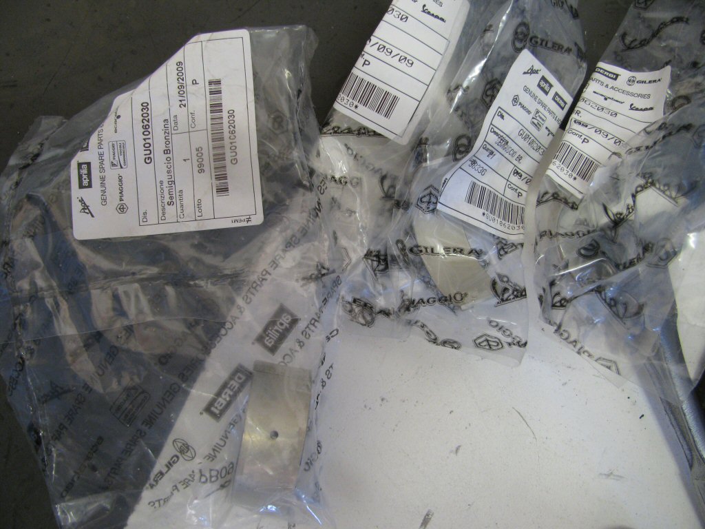
New shells.
Photo courtesy of Gregory Bender.
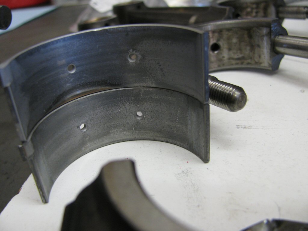
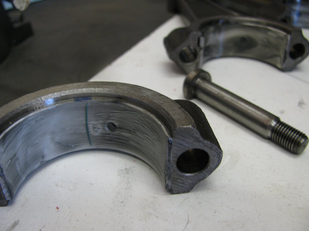
Old shells...these two weren't so bad.
Photo courtesy of Gregory Bender.
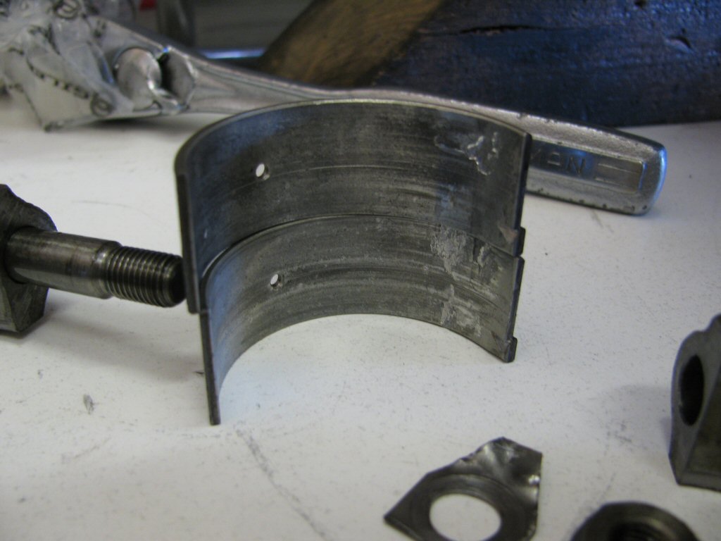
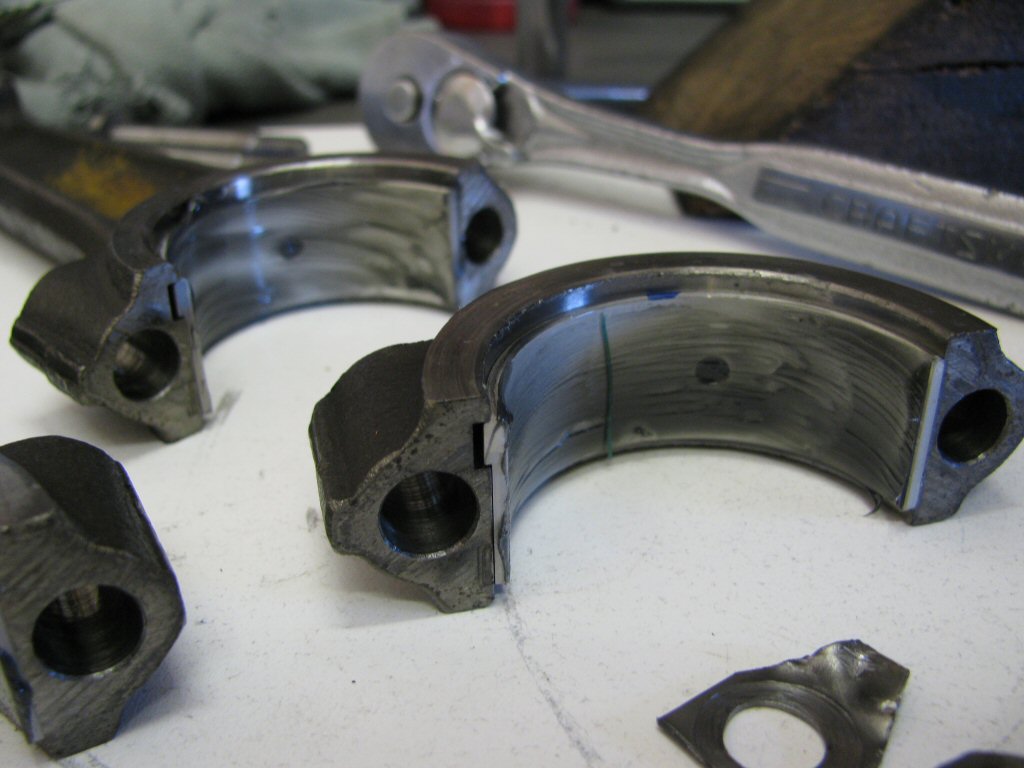
Old shells...these two are clearly shot.
Photo courtesy of Gregory Bender.
Assembly lube with plastigauge in place.
Photo courtesy of Gregory Bender.
Close up of new shells with plastigauge.
Photo courtesy of Gregory Bender.
Close up of new shells with plastigauge.
Photo courtesy of Gregory Bender.
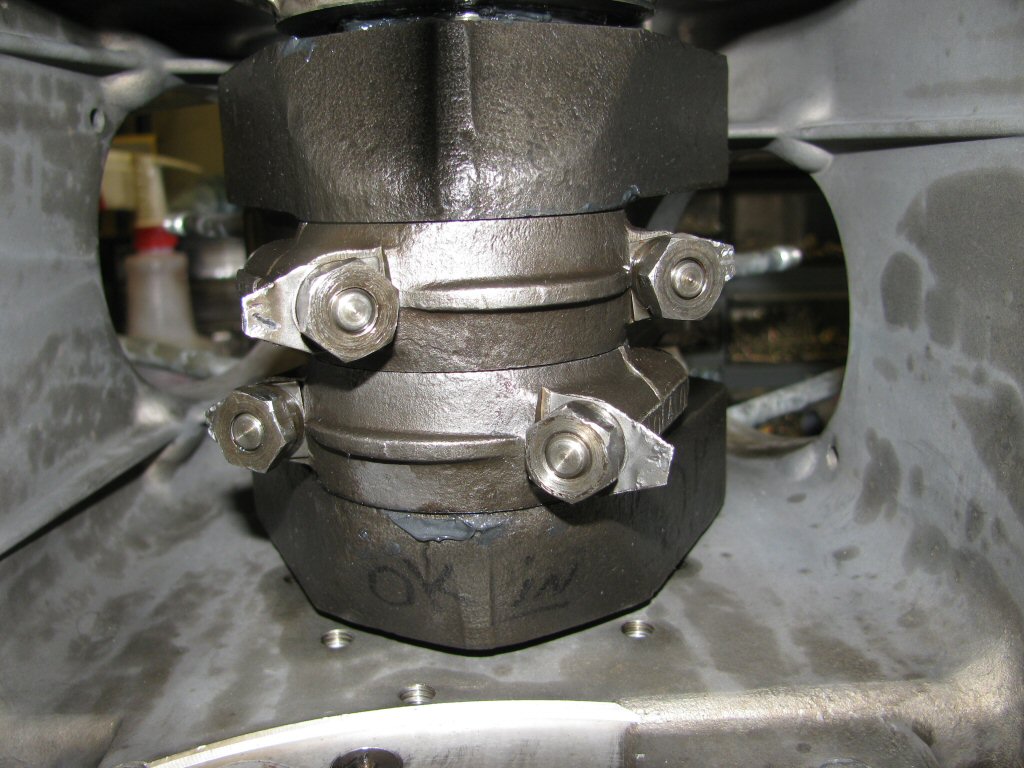
Connecting rods in place...checking clearances with plastigauge.
Photo courtesy of Gregory Bender.
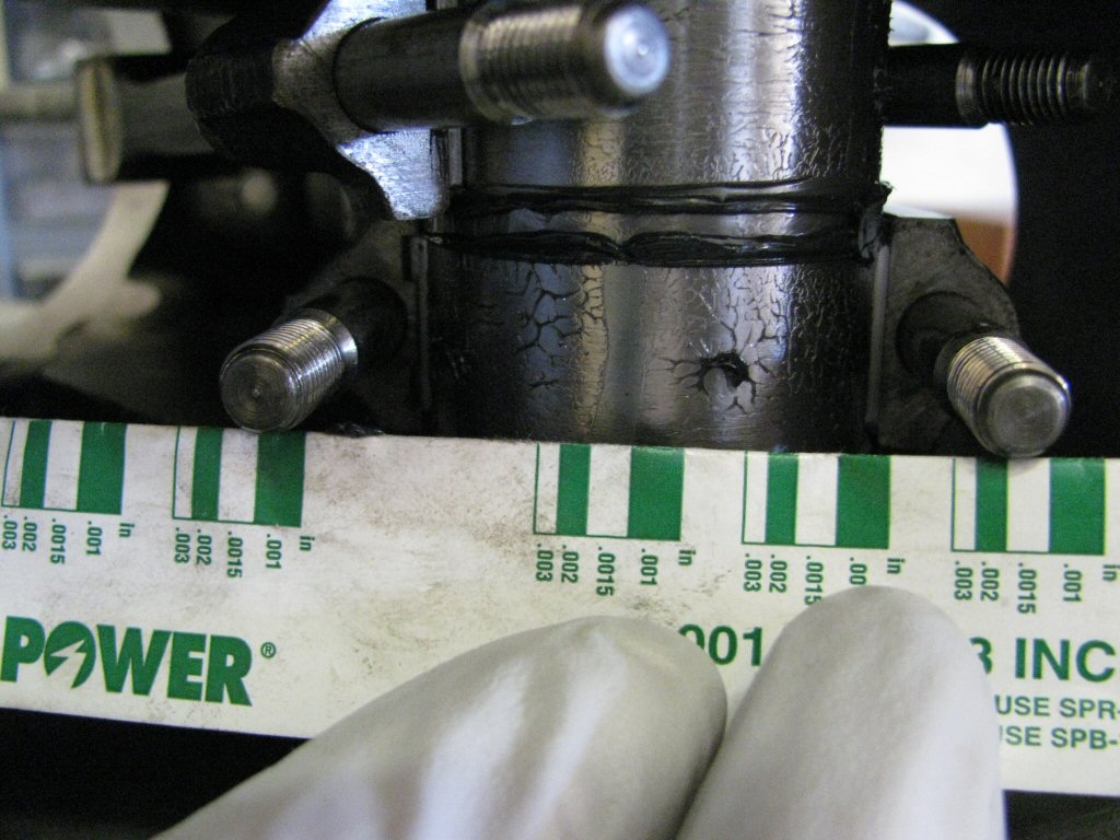
Right connecting rod measures out at 0.0015 inch. Nice.
Photo courtesy of Gregory Bender.

Left connecting rod measures out at 0.0015 inch, too. Good.
Photo courtesy of Gregory Bender.
Platigauge cleaned off, shells relubed torqued in place.
Photo courtesy of Gregory Bender.
Bendy tabs in place.
Photo courtesy of Gregory Bender.
Bendy tabs in place.
Photo courtesy of Gregory Bender.
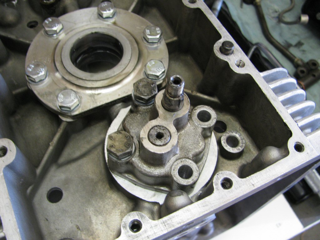
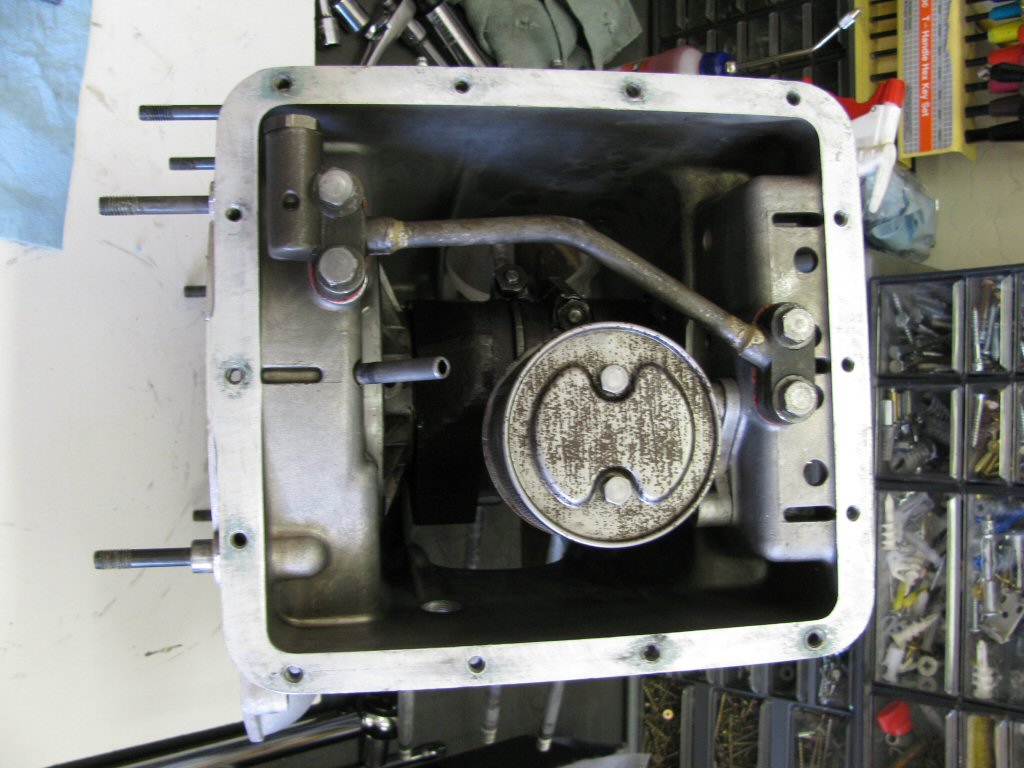
Oil pick up being installed.
Photo courtesy of Gregory Bender.
Oil pump torqued in place.
Photo courtesy of Gregory Bender.
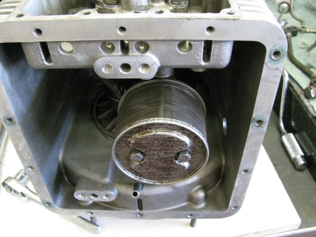
Oil screen secured in place.
Photo courtesy of Gregory Bender.
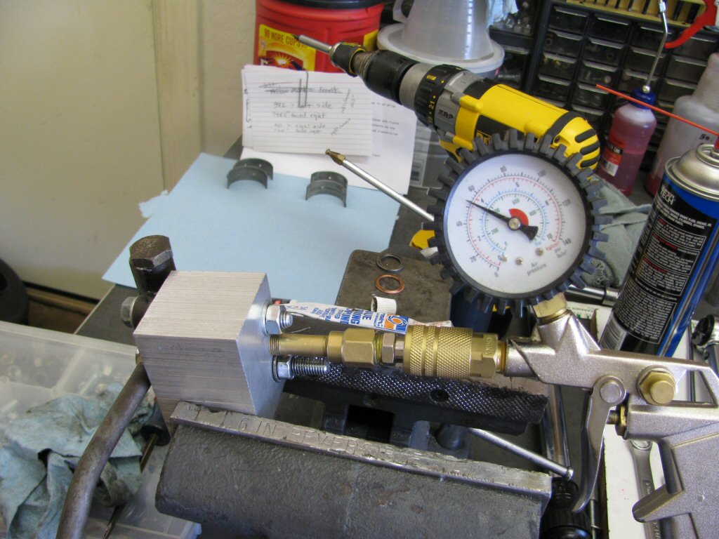
Tested and ground the oil pressure relief valve. It now holds pressure up to 54 PSI without bleed off. Amazing. I've never gotten another one to be so good. Blows off at 60 PSI or just a pound or two over). Exactly where we want it to be.
Photo courtesy of Gregory Bender.
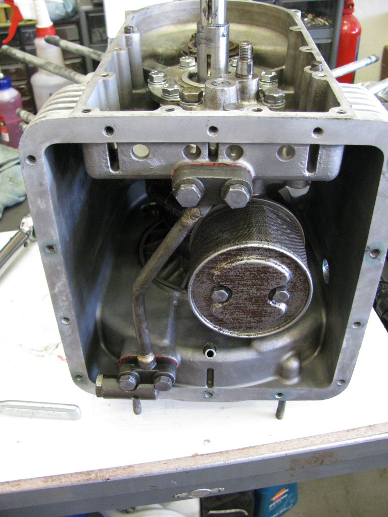
Oil line secured in place.
Photo courtesy of Gregory Bender.
Engine case tipped up to aid installation of oil pan.
Photo courtesy of Gregory Bender.
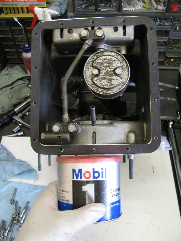
Gasket lubed with grease and put in place.
Photo courtesy of Gregory Bender.
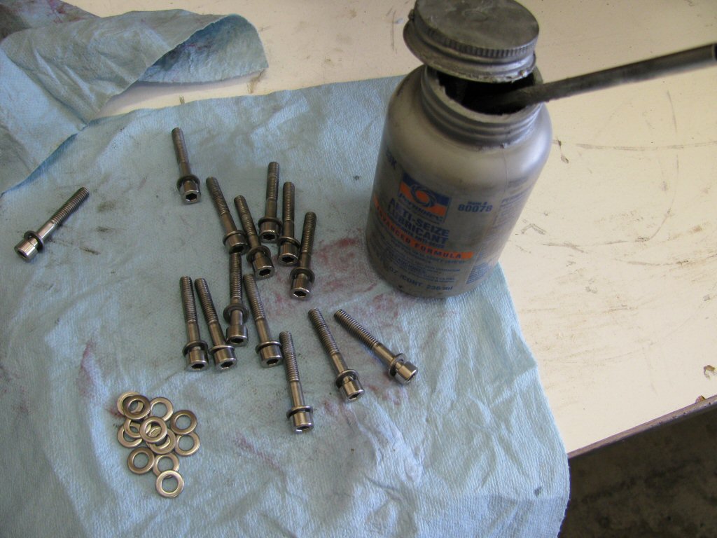
Stainless fasteners coated with anti-seize.
Photo courtesy of Gregory Bender.
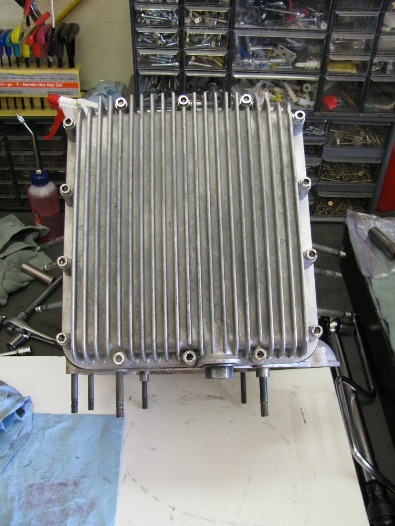
The oil pan secured in place.
Photo courtesy of Gregory Bender.
Time for the tappets.
Photo courtesy of Gregory Bender.
They look so pretty!
Photo courtesy of Gregory Bender.
Lubed and inserted.
Photo courtesy of Gregory Bender.
Lubed and inserted.
Photo courtesy of Gregory Bender.
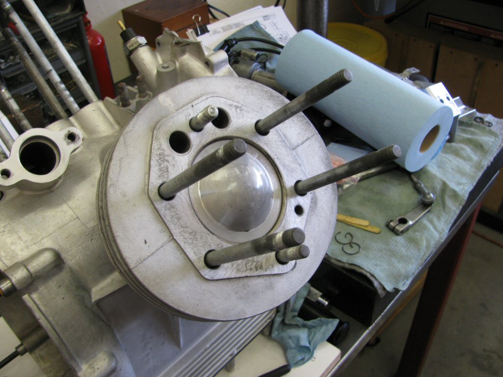
Base gasket in place with cylinder stud O-rings.
Photo courtesy of Gregory Bender.
Base gasket in place with cylinder stud O-rings.
Photo courtesy of Gregory Bender.
Installing piston into cylinder.
Photo courtesy of Gregory Bender.
Installing piston into cylinder.
Photo courtesy of Gregory Bender.
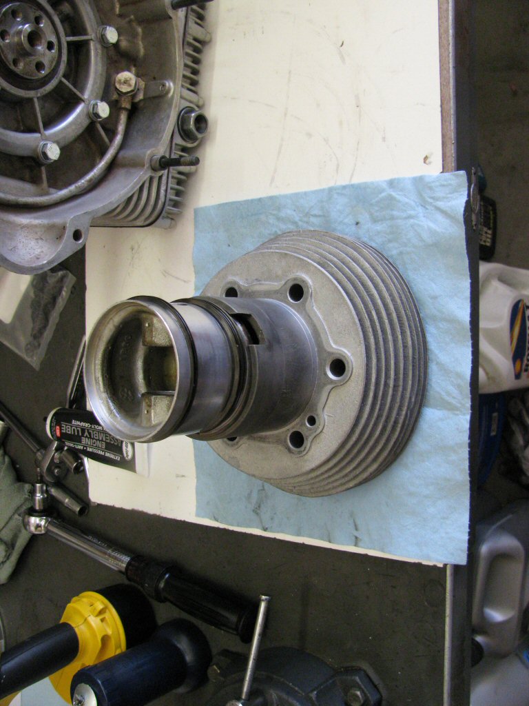
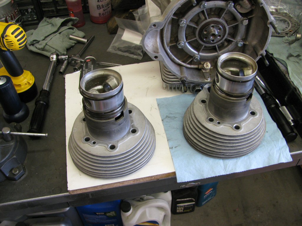
Pistons in place, ready to put on the connecting rods.
Photo courtesy of Gregory Bender.
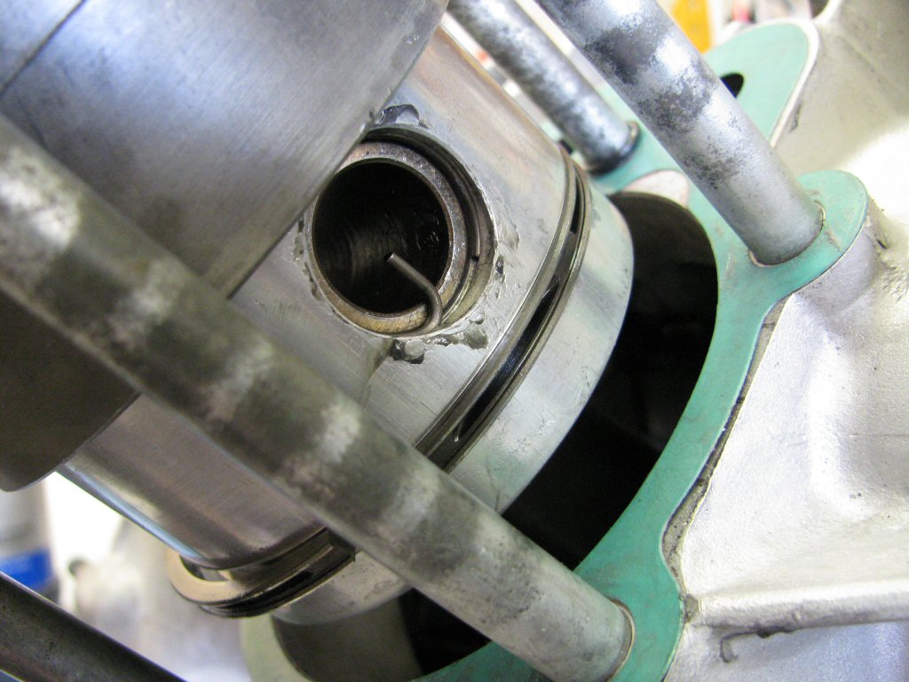
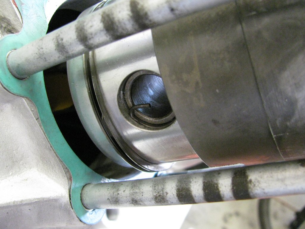
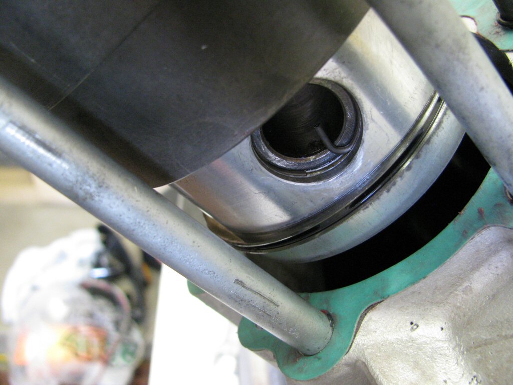
Installed with circlip in place.
Photo courtesy of Gregory Bender.
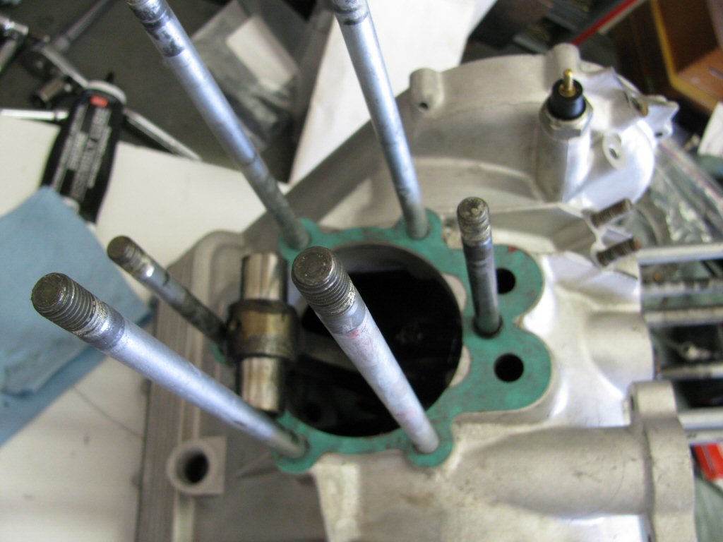
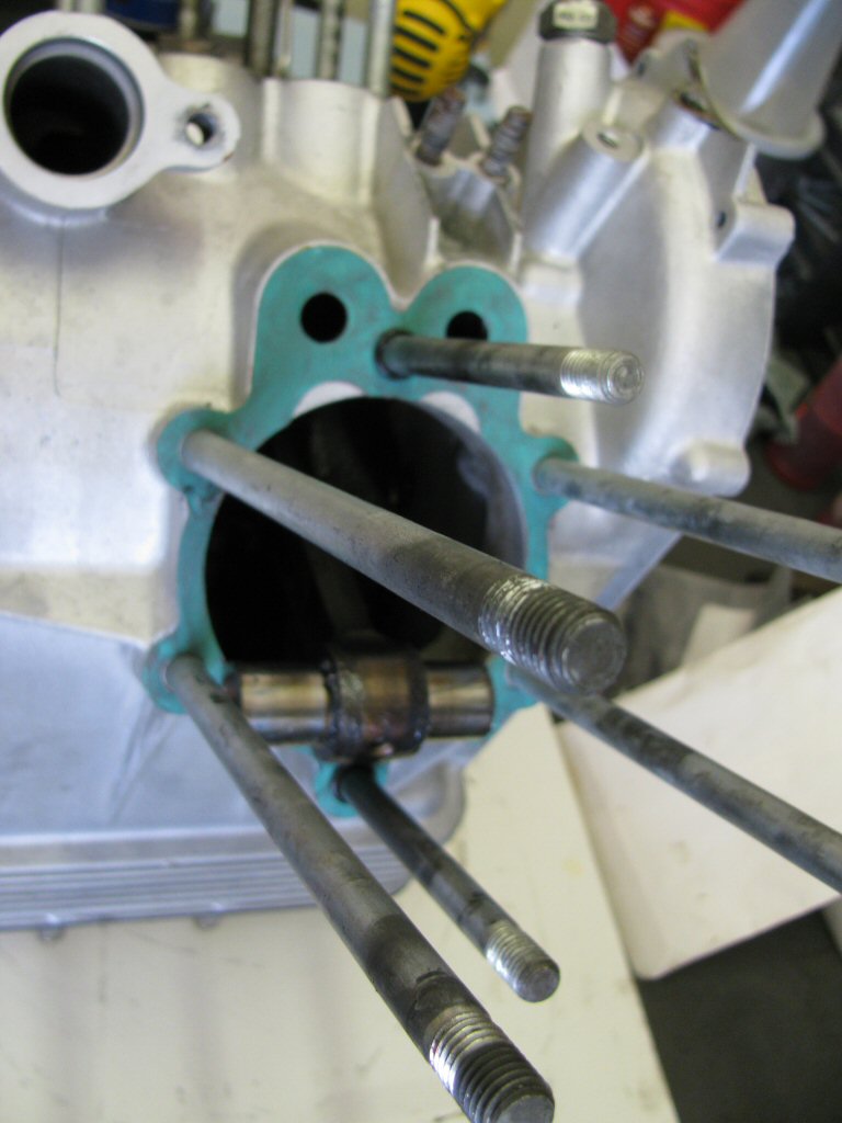
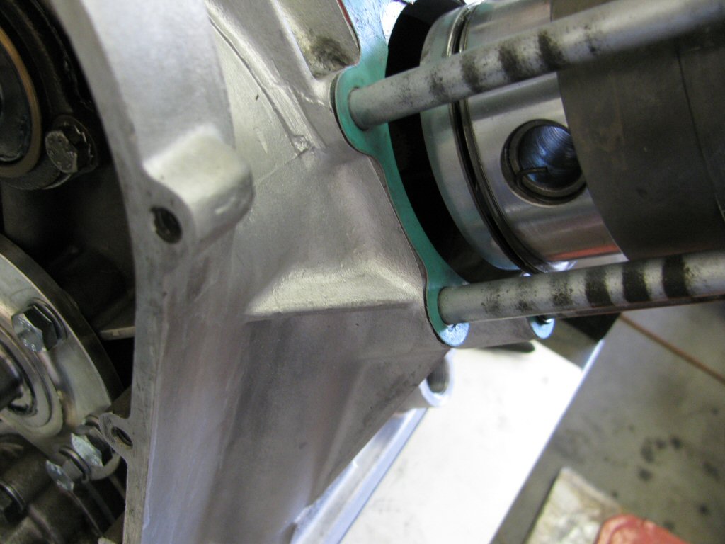
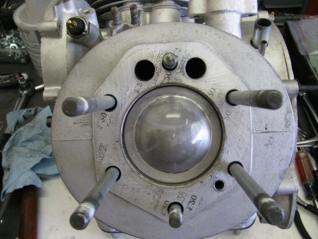
Cylinder pushed down in place.
Photo courtesy of Gregory Bender.
Installed with circlip in place.
Photo courtesy of Gregory Bender.
Installed with circlip in place.
Photo courtesy of Gregory Bender.
Installed with circlip in place.
Photo courtesy of Gregory Bender.
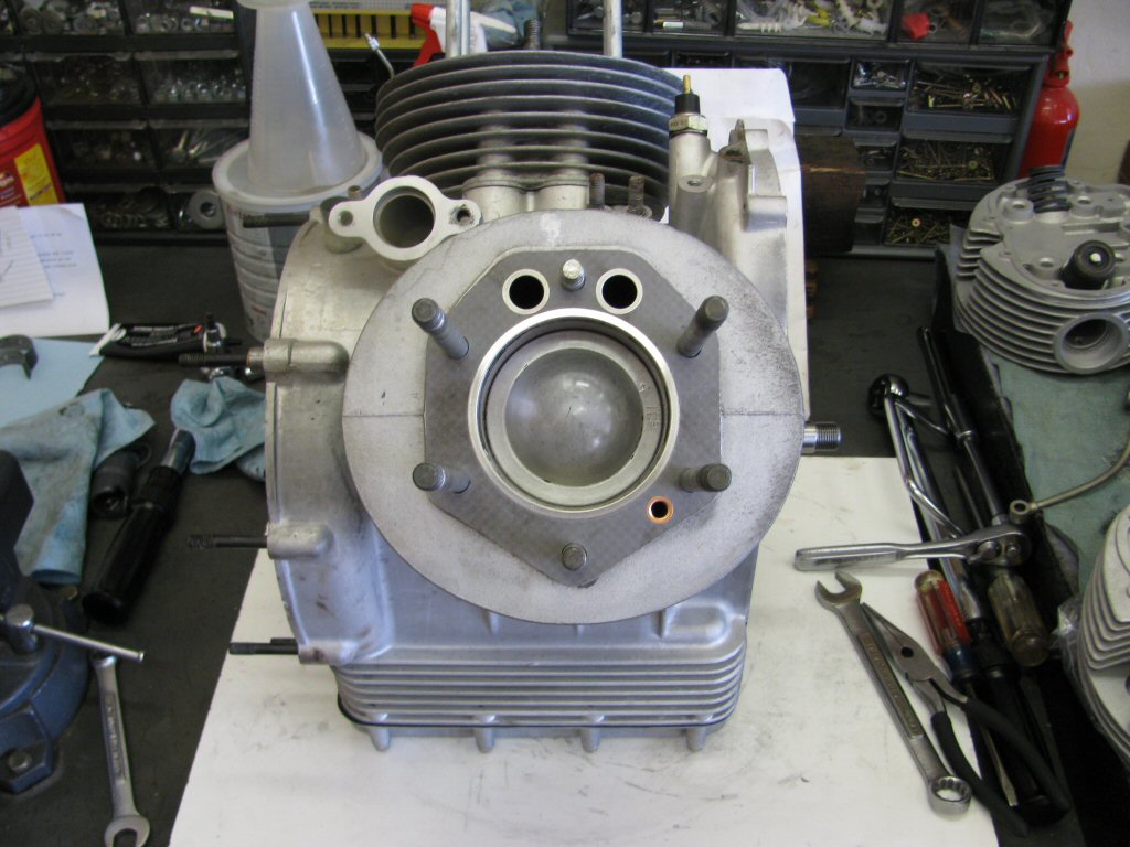
Cylinder pushed down in place.
Photo courtesy of Gregory Bender.
New head gasket in place.
Photo courtesy of Gregory Bender.
Cylinder head installed.
Photo courtesy of Gregory Bender.
New head gasket in place.
Photo courtesy of Gregory Bender.
Cylinder head installed.
Photo courtesy of Gregory Bender.
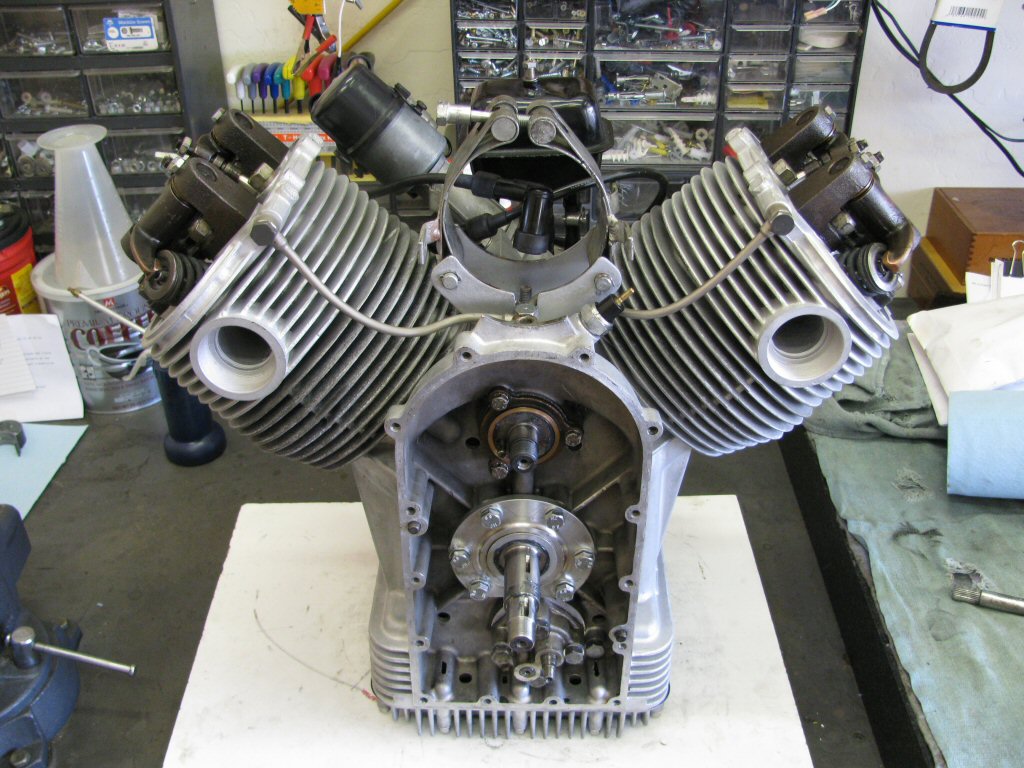
Top end components installed, oil line installed, generator bracket installed, distributor installed, breather box installed.
Photo courtesy of Gregory Bender.
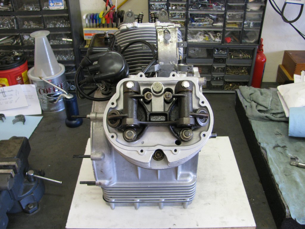
Top end components installed, oil line installed, generator bracket installed, distributor installed, breather box installed.
Photo courtesy of Gregory Bender.
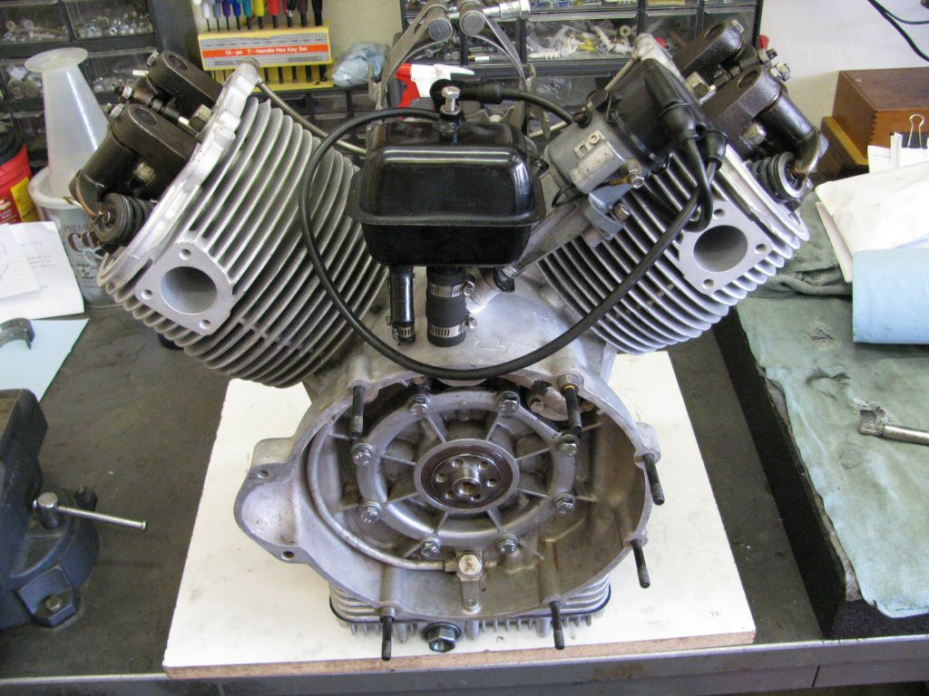
Top end components installed, oil line installed, generator bracket installed, distributor installed, breather box installed.
Photo courtesy of Gregory Bender.
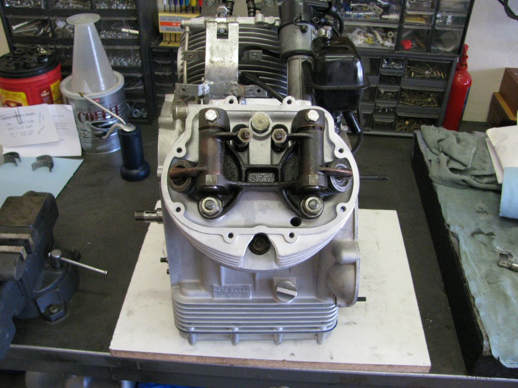
Top end components installed, oil line installed, generator bracket installed, distributor installed, breather box installed.
Photo courtesy of Gregory Bender.
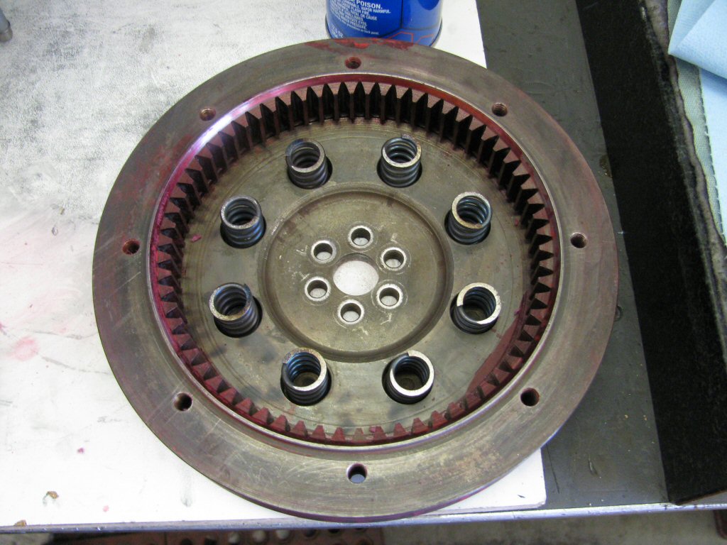
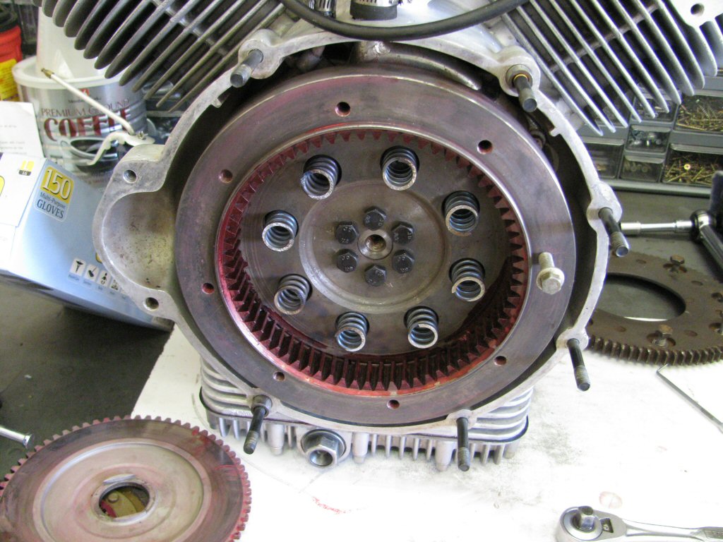
Flywheel with new springs. Red color is from layout dye that was used when diagnosing engine/transmission misalignment.
Photo courtesy of Gregory Bender.
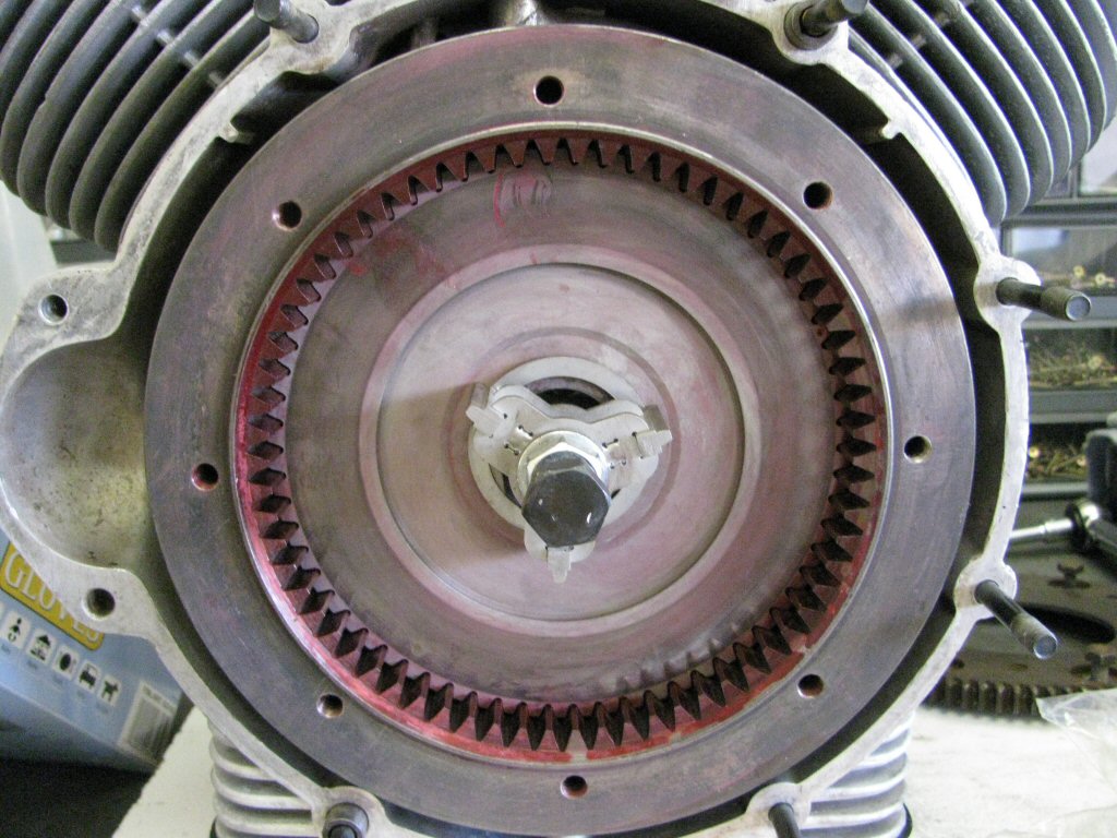
Flywheel torqued in place, hardened bolts with blue Loctite.
Photo courtesy of Gregory Bender.
Pressure plate installed and compressed with special tool.
Photo courtesy of Gregory Bender.
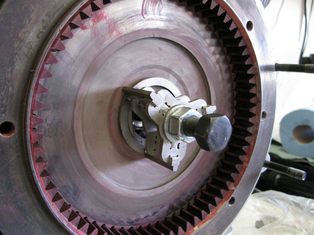
Pressure plate installed and compressed with special tool.
Photo courtesy of Gregory Bender.