Karburator - tegninger, skema, og en how-to guide.
Author: Jens Lyck
Det er såmænd ikke så svært - og så aligevel. De fleste kan forstå den grundlæggende funktion af karburatoren, men der er et temmelig stort stykke vej før man også bliver god til at indstille den.
Hvis din cykel er nogenlunde standard går du ikke helt galt i byen ved at starte med fabriksindstillingen som du kan finde herunder. Herfra kan du så efter lyst og evne eksperimentere med dyser og nåle. Det er ganske billigt på Dell Orto'erne.
Bemærk at alle de grundlæggende ting som tænding, ventiler, og synkronisering af de to karburatorer skal være i orden før du begynder at lege med dyserne, ellers spilder du din tid.
Hvis du ikke har mod på at bruge en masse tid og kræfter på at lære det, foreslår jeg at du betaler nogen for at gøre arbejdet, og så holder dig til at tømme svømmerhusene og synkronisere en gang imellem.
Dell Orto karburatorer er meget nemme at gå til. De nødvendige informationer kan du finde på disse sider, men husk: DU SKRUER PÅ EGET ANSVAR !
Table of contents
Fabriksindstillinger
Synkronisering af Dellorto PHM og PHF karburatorer uden brug af vacuummeter
Eksplosionstegning
Numrering af dyser og nåle
Jetting guide
Fabriksindstillinger
Her kan du se hvilke dyser fabrikken satte i dine karburatorer.
| MC | Karburator | Tomgangsdyse | Hoveddyse | Gasnål | Clip pos (Fra top) | Nåledyse | Spjæld |
|---|---|---|---|---|---|---|---|
| V7 Sport, 750S, S3, 850T | VHB 30 | 50 | 142 | V-9 | 2 | 265 | 40 |
| T3, T4 | VHB 30 | 50 | 120 | V-9 | 2 | 265 | 40 |
| Le Mans 1 | PHF 36 | 60 | 135 | K-5 | 2 | 265 | 60/1 |
| Le Mans 2 | PHF 36 | 60 | 140 | K-5 | 2 | 265 | 60/1 |
| Le Mans 3 | PHF 36 | 50 | 115 | K-18 | 3 | 268 | 60/3 |
| Le Mans 4 | PHM 40 | 57 | 145 | K-19 | 3 | 268 | 60/5 |
| Le Mans 5, Big valve California 3 | PHM 40 | 57 | 145 | K-19 | 3 | 268 | 60/5 |
| California 2, SP2 | VHB 30 | 50 | 125 | V-9 | 2 | 265 | 40 |
| T5, CX100, 1000SP, Convert, G5 | VHB 30 | 50 | 130 | V-9 | 2 | 265 | 40 |
| California 2, SP2, T5, CX100, 1000SP, Convert, G5 | PHF 30 | 50 | 125 | K-23 | 3 | 264 | 50/3 |
| California 3, Mille GT | PHF 30 | 50 | 130 | K-23 | 3 | 264 | 50/3 |
| 1000S | PHM 40 | 57 | 145 | K-19 | 3 | 266 | 60/5 |
| Strada 1000, 1000S, SP3, California 3 | PHF 36 | 50 | 130 | K-18 | 3 | 268 | 60/3 |
| California 1100 | PHF 36 | 50 | 130 | K-18 | 2 | 266 | 60/3 |
| Sport 1100 | PHM 40 | 57 | 152 | K-18 | 3 | 266 | 60/5 |
Bemærk at LM3 kører med en special udgave af PHF36'eren med et særligt forstøversystem der gør at den kan køre med mindre hoveddyse.
Synkronisering af Dellorto PHM og PHF karburatorer uden brug af vacuummeter
Hvad nu hvis du er nødt til at synkronisere ude i bushen eller når et vacuummeter ikke er tilgængeligt? Jeg bruger en enkel fremgangsmåde som andre måske også kan drage nytte af (med fare for at dem, der virkelig har styr på mekaniske ting, synes dette er banalt og en selvfølge!!!). Jeg har flere gange brugt denne fremgangsmåde og derefter efterprøvet ved hjælp af et vacuummeter, og resultatet er overraskende godt! Det er meget sjældent at jeg har været nødt til at foretage nogen særlig efterjustering! (I instruktionsbogen til min cykel, en Le Mans III, beskrives en håbløs metode med at føle på eksostrykket bag på etc.... Glem den!).
- Forberedelse
- Det er vigtig ikke at springe over nogen af punkterne - A, B eller C - og at man følger dem i den rigtige rækkefølge. Alle operationerne foregår med motoren slukket, indtil du skal justere tomgangen i pkt. D. Det forudsættes at chokeren er rigtig justeret med en frihøjde på minimum 3 mm, så den ikke driller med justeringen af karburatorerne.
- Fjern luftfiltrene i tilfælde af at du har KN-filtre eller lignende. Hvis du har originale filtre så åben ved indsugningen til karburatorerne, nok til at du kan få en finger ind i indsugningen og let kan få fat i det store stempel (spjældet) som spærrer midt inde i karburatoren.
- Skru tomgangsskruerne (de store skruer med fjedre udenpå) på begge karburatorer næsten HELT UD, så de ikke længere løfter spjældet i karburatoren.
- Slæk begge gaskabler HELT. Nu skal spjældene inde i karburatorerne ligge helt mod bunden af karburatorerne - du kan høre at spjældene slår imod bunden (hvis spjældene i karburatorerne fortsat hænger i kablerne, så har du forkert type kabler, eller også er der noget andet i vejen med kabelsystemet, og dette skal laves før du går videre).
- Synkronisering af tomgangsskruerne
- Stik en finger ind i indsugningen på den ene karburator og lad fingerspidsen ligge mod spjældet i karburatoren på en sådan måde at du på samme tid kan mærke BÅDE spjældet og væggen i karburatoren. En følsom fingerspids er det vigtigste værktøj her! Skru tomgangsskruen på denne karburator indad (med uret) til du føler med fingeren at spjældet begynder at bevæge sig opad. Skru tomgangsskruen lidt frem og tilbage indtil du finder det EKSAKTE punkt hvor skruen begynder at tage fat, dvs. løfte spjældet.
- Gør det samme med den anden karburator.
- Skru nu tomgangsskruerne indad (med uret) på BEGGE karburatorerne med SAMME ANTAL OMDREJNINGER (for eksempel 2 omdrejninger). Dette er for at finde et synkront startpunkt for tomgangsjusteringen senere. Vær lidt nøje med dette, dvs. læg mærke til vinklen på kærven i tomgangsskruen før du begynder at skrue, og skru med en halv omdrejning ad gangen, og tæl!
- Synkronisering af gaskablerne
- Stram begge gaskabler til du har cirka samme slip i begge to. Det er meget vigtig at du ikke strammer så meget at spjældene hænger i kablerne! På dette punkt må du gerne ha en anelse MERE slip i gassen end du ka li!
- Stik en finger ind i hver karburator PÅ SAMME TID, som beskrevet i pkt. 5, og lad en hjælper dreje lidt på gashåndtaget (min datter på 8 klarer jobbet fint!). Det vil sige: Vrid gentagne gange fra nul gas til meget lidt gas. Du vil nu kunne mærke med fingrene om det ene kabel BEGYNDER at ta fat tidligere end det andet. Juster gaskablerne indtil du har tilpasset dødgang på gassen efter smag, og begge kablerne BEGYNDER at løfte spjældet i hver sin karburator på SAMME TID!
- Tjek at gashåndtaget virkelig kan løfte spjældene i karburatorerne helt op. (Det kan være at nogen har monteret et gashåndtag som egentlig ikke kan gi fuld gas!). Dette gøres ved at gi fuld gas (uden at motoren går!) og mærke efter med fingeren i indsugningen at spjældet er kommet helt i top i karburatoren. Det vil sige at underkant af spjældet flugter med karburatorhuset oppe i indsugningskanalen.
- Tjek at spjældene i karburatorerne ikke trækkes UD af karburatorhuset ved fuld gas. Hvis dette ikke er i orden så mærkes det når du kører på fuld gas og du mærker at cyklen faktisk øger farten hvis du letter en smule på gassen fra fuld gas. Dette tjekkes ved at gi fuld gas (uden at motoren går!) og mærke efter med fingeren i indsugningen at underkanten af spjældet IKKE er kommet ud af indsugningskanalen. Hvis dette sker bør du justere stoppemekanismen på gashåndtaget.
- Justering af tomgang
- Monter luftfiltrene, start cyklen og kør motoren varm.
- Juster tomgangen tilpas ved at skrue tomgangsskruerne efter behov på BEGGE karburatorer med SAMME ANTAL OMDREJNINGER. Vær lidt nøje med dette, dvs. læg mærke til vinklen på kærven i tomgangsskruen før du begynder at skrue, og skru med en kvart omgang ad gangen, og tæl!. Det vil sige, at hvis du for eksempel ønsker højere tomgang så skru indad (med uret) en kvart omgang på BEGGE karburatorer, og hvis yderligere øgning er nødvendig så skru endnu en kvart omgang på BEGGE sider. Etc... etc...etc...
- Justering af blanding
- Skru blandingsskruen (den lille der næsten er undersænket på karburatoren) helt ind (ikke hårdt!). Skru den derefter 2 omgange ud igen på begge karburatorer.
- Med varm motor gående i tomgang, skrues blandingsskruen ind eller ud indtil den hurtigste tomgang opnås. Gør dette med een karburator ad gangen. På dette punkt tror jeg(?) ikke det er nogen pointe i at blandingsskruerne har nøjagtig samme antal omdrejninger fra bunden af begge karburatorer, så længe højest muligt omdrejningstal i tomgang er opnået. Men det skulle være mærkeligt hvis det er vældig stor forskel på dem?
- Hvis det ender med at blandingsskruen er mere end 3 omdrejninger fra bunden så er det sandsynligt at du har for lille tomgangsdyse. Hvis det ender med at blandingsskruen er mindre end en halv omdrejning fra bunden så er det sandsynlig at du har for stor tomgangsdyse.
- Hvis det er nødvendig, så efterjuster tomgangen ved at følge pkt. D (NB: synkront med samme antal omdrejninger på tomgangsskruen på begge sider!).
(Hvis du har adgang til et vacuummeter så kan du for sjov skyld koble det på, og finde ud af hvor dygtig du har været! )
Go fornøjelse.
Eksplosionstegning
Med reservedelsnumre.
| Diag No. | Part No. | Description | Sizes/options available |
|---|---|---|---|
| 1 | 8639 | Slide | 401,501,503,505,601,603 & 605 |
| 2 | 8530 | Needle | K1 to K95 |
| 3 | 8540 | Atomizer AB | 258,60,62,64,65,66,68,70,72,75,78,80,90 & 300 |
| 3 | 12599 | Atomizer DR | 266,268,270 & 272. |
| 4 | 9980 | Idle emulsion tube | Not fitted to all models |
| 5 | 6413 | Main Jet | 56 to 330, in steps of 1,2 & 3. Please ask. |
| 6 | 1486 | Idle jet (short) | 30 to 198, in steps of 1,2 & 3. Please ask |
| 7 | 7746 | Choke jet | 45,50,55,60,65,70,75,80,85 & 90 |
| 8 | 7851 | Pump jet | 30,33,35,38,40,42,45,48,50,55,60,65,70,75,90,150 |
| 9 | 10375 | Float needle valve | 150, 170, 200, 225 |
| 9 | 8649 | Float needle valve | 250, 270, 300, 350, 400 |
| 10 | 7450 | Float | .1, .2 & .3 |
| 11 | 6429 | Top cover screw | |
| 12 | 1581 | Spring washer | |
| 13 | 8826 | Top paper gasket | |
| 14 | 8542 | Screw | |
| 15 | 11779 | Slide rod | |
| 16 | 11798 | Top casting | |
| 17 | 8726 | Spindle seal | |
| 18 | 8727 | Spindle seal cover | |
| 19 | 8535 | Pump arm pin | Metal top |
| 19 | 10924 | Pump arm pin | Plastic top |
| 20 | 9383 | Spring | |
| 21 | 11777 | Slide rod | |
| 22 | 10451 | circlip | |
| 23 | 8941 | Throttle lever | |
| 24 | 11773 | Needle washer | |
| 25 | 9596 | Needle circlip | |
| 26 | 8633 | Top cover O ring | |
| 27 | 3718 | Washer | |
| 28 | 11776 | Slide rod | |
| 29 | 11774 | Spring guide | |
| 30 | 11786 | External return spring | |
| 31 | 11775 | Spring guide | |
| 32 | 11787 | Throttle cable support | |
| 33 | 6435 | Screw | |
| 34 | 4957 | Spring washer | |
| 35 | 11788 | Left hand throttle support | |
| 36 | 8825 | Dome top cover | |
| 37 | 9042 | Allen screw | |
| 38 | 5011 | Spring washer | |
| 39 | 8830 | Cable arm | |
| 40 | 8725 | Spindle seal | |
| 41 | 10069 | Slide rod guide | |
| 42 | 7415 | Pump arm spring | |
| 43 | 8426 | Pump arm | |
| 44 | 3698 | 90 Degree cable elbow | |
| 44 | 3600 | 70 Degree cable elbow | |
| 44 | 9330 | 40 Degree cable elbow | |
| 45 | 1692 | Adjuster locknut (for 1481) | |
| 46 | 1481 | Cable adjuster | |
| 47 | 1476 | Rubber cable cap | |
| 48 | 1104 | Cable adjuster | |
| 49 | 1691 | Adjuster locknut (for 1104) | |
| 50 | 3128 | Choke support | |
| 51 | 3133 | Choke return spring | |
| 52 | 3238 | Choke piston | |
| 53 | 11650 | Long choke body screw | |
| 54 | 8711 | Choke body screw | |
| 55 | 8887 | Choke housing | |
| 56 | 8888 | Choke housing gasket | |
| 57 | 11651 | Choke housing spacer (LM) | |
| 57 | 7749 | Mixture screw standard |
|
| 58 | 11084 | Mixture screw Guzzi |
|
| 59 | 9336 | Mixture screw spring | |
| 60 | 8260 | Mixture screw washer | |
| 61 | 8678 | Mixture screw O ring | |
| 62 | 10747 | Pump jet holder | |
| 63 | 6426 | Pump jet holder fibre washer | |
| 64 | 6173 | Pump jet O ring | |
| 65 | 7673 | Throttle stop screw | |
| 66 | 4670 | Throttle stop screw spring | |
| 67 | 4650 | Washer | |
| 68 | 7540 | O ring | |
| 69 | 10800 | Pump non return valve | |
| 70 | 8556 | Pump cover | |
| 71 | 8598 | Adjuster screw O ring | |
| 72 | 8599 | Pump adjuster locknut | |
| 73 | 8539 | Pump adjustment screw | |
| 74 | 8428 | Screw | |
| 75 | 7626 | Diaphagm spring | |
| 76 | 8555 | Pump diaphragm | |
| 77 | 9278 | Diaphragm gasket | |
| 78 | 8885 | Main jet holder | |
| 79 | 11785 | Operating lever, RH | |
| 80 | 11799 | Top casting | |
| 81 | 6109 | Fuel banjo filter | |
| 82 | 9250 | Plastic fuel union | |
| 82 | 6273 | Metal fuel union | |
| 82 | 7890 | Double fuel union | |
| 83 | 4568 | Fuel union bolt | |
| 84 | 8557 | Non return valve | |
| 85 | 6288 | Needle valve fibre washer | |
| 86 | 7451 | Float bowl O ring | |
| 87 | 7346 | Float pivot pin | |
| 88 | 10557 | Float bowl | |
| 89 | 4057 | Float bowl nut seal | |
| 90 | 10238 | Float bowl nut | |
| 91 | 52560 | PHM N, cranked top | |
| 91 | 52520 | PHM A,B,N,V gasket set | |
| 91 | 52544 | PHM..H,L,M,P,R,T,S,Z gasket set | |
| 91 | 52545 | PHM A,B,N,V gasket set | |
| 92 | 4052 | Fuel union seal | |
| 93 | 9573 | Short plastic trumpet | |
| 94 | 8673 | Long trumpet with wire gauze | |
| 95 | 8128 | Clamp nut | |
| 96 | 8127 | Clamp bolt | |
| 97 | 8528 | Clamp | |
| 98 | 8596 | PHM38 R90S mounting sleeve | |
| 99 | 10923 | Plastic top | |
| 100 | 8550 | Slide spring 0.7kg/70mm | |
| 100 | 8532 | Slide spring 1.1kg/70mm | |
| 100 | 9389 | Slide spring 1.4kg/70mm | |
| 101 | 8525 | Needle clip |
Numrering af dyser og nåle
Mon der findes en højere mening med det hele ?
Dyser
det er ganske enkelt - målet på dysen opgives efter størrelsen på hullet i 100-dele mm. Altså har en 60-dyse et hul på 0,6mm og en 268 dyse er 2,68mm. Bemærk at gevindet og den udvendige størrelse på dysen afhænger af hvor den er placeret i karburatoren. Så når du bestiller dyser skal du fortælle om du vil have hoveddyse, tomgangsdyse etc. OG størrelsen på dysen.
Gasnål
Her er det mere tricky. Der er så mange betydende mål på en gasnål at det ikke giver nogen logisk mening at numrere efter et enkelt af dem. Derfor har de fået tilsyneladende tilfældige numre, og for at gennemskue hvad de dækker over er det nødvendigt at bruge nedenstående tegning og skema.
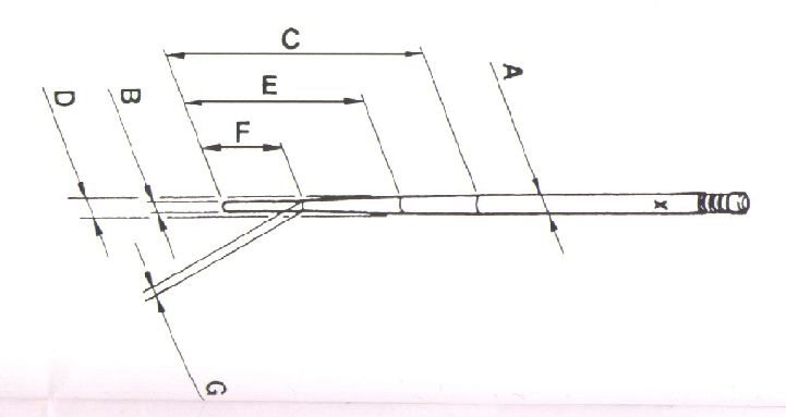
| Type | Ø-A | Ø-B | C | Ø-D | E | F | G |
|---|---|---|---|---|---|---|---|
| K-1 | 2,45 | 1,75 | 37 | - | - | - | - |
| K-2 | 2,45 | 1,75 | 42 | - | - | - | - |
| K-3 | 2,50 | 1,5 | 39 | - | - | - | - |
| K-4 | 2,45 | 1,5 | 39 | - | - | - | - |
| K-5 | 2,45 | 1,5 | 37 | - | - | - | - |
| K-6 | 2,45 | 1,75 | 39 | - | - | - | - |
| K-7 | 2,45 | 1,25 | 39 | - | - | - | - |
| K-8 | 2,50 | 1,5 | 37 | - | - | - | - |
| K-9 | 2,45 | 1,5 | 42 | - | - | - | - |
| K-11 | 2,50 | 1,25 | 39 | - | - | - | - |
| K-12 | 2,48 | 1,75 | 32 | - | - | - | - |
| K-13 | 2,45 | 1,25 | 38 | - | - | - | - |
| K-14 | 2,48 | 1,75 | 33 | - | - | - | - |
| K-15 | 2,50 | 0,6 | 26 | - | - | - | - |
| K-16 | 2,50 | 1,75 | 39 | - | - | - | - |
| K-17 | 2,42 | 1,75 | 40 | - | - | - | - |
| K-18 | 2,50 | 1,4 | 38 | - | - | - | - |
| K-19 | 2,50 | 1,4 | 40 | - | - | - | - |
| K-20 | 2,50 | 1,4 | 42 | - | - | - | - |
| K-21 | 2,50 | 1,8 | 38 | - | - | - | - |
| K-22 | 2,50 | 1,8 | 40 | - | - | - | - |
| K-23 | 2,50 | 1,8 | 42 | - | - | - | - |
| K-24 | 2,50 | 1,2 | 38 | 2,13 | 18 | - | - |
| K-25 | 2,50 | 1 | 36 | 2,15 | 18 | - | - |
| K-27 | 2,50 | 1,8 | 44 | - | - | - | - |
| K-28 | 2,50 | 1,8 | 41 | - | - | - | - |
| K-29 | 2,45 | 1,25 | 42 | - | - | - | - |
| K-30 | 2,50 | 1,4 | 36 | 2,15 | 18 | - | - |
| K-32 | 2,48 | 1,7 | 44 | - | - | - | - |
| K-33 | 2,50 | 1,8 | 44 | - | - | - | - |
| K-34 | 2,50 | 1,4 | 40 | 2,11 | 18 | - | - |
| K-35 | 2,50 | 1,4 | 43 | - | - | - | - |
| K-36 | 2,50 | 1,4 | 38 | 2,17 | 20 | - | - |
| K-37 | 2,50 | 1,4 | 39 | 2,12 | 18 | - | - |
| K-38 | 2,50 | 1,4 | 38 | 2,13 | 18 | - | - |
| K-39 | 2,48 | 1,45 | 36 | 2,28 | 26 | - | - |
| K-40 | 2,50 | 1,4 | 40 | 2,18 | 22 | - | - |
| K-41 | 2,50 | 1,4 | 40 | 2,14 | 22 | - | - |
| K-42 | 2,50 | 1,4 | 38 | 2,16 | 22 | - | - |
| K-43 | 2,50 | 1,4 | 42 | 2,16 | 26 | - | - |
| K-44 | 2,50 | 1,4 | 39 | 2,06 | 20 | - | - |
| K-45 | 2,48 | 1,3 | 36 | 2,28 | 26 | - | - |
| K-46 | 2,50 | 1,4 | 40 | 2,15 | 20 | - | - |
| K-48 | 2,48 | 1,6 | 36 | 2,25 | 25 | 11 | 1,60 |
| K-49 | 2,50 | 1,4 | 39 | 2,20 | 26 | - | - |
| K-50 | 2,50 | 1,4 | 39 | 2,27 | 26 | - | - |
| K-52 | 2,50 | 1,6 | 36 | 2,25 | 25 | 11 | 1,60 |
| K-53 | 2,52 | 1,6 | 36 | 2,25 | 25 | 11 | 1,60 |
| K-54 | 2,48 | 1,5 | 40 | 2,108 | 18 | - | - |
Jetting guide
Denne guide er egentlig skrevet til japanske karburatorer, men principperne er de samme. På groveste vis sakset fra nettet og i øvrigt på engelsk.
Quick Jetting Guide for Mikuni and Keihin CV (carburetors with movable jet needles)
The following tips and insights are for your information only. These will not make you an expert tuner. We recommend that if you are a novice, you consult a professional mechanic or technician for your specific needs. The author cannot be responsible for your interpretation and usage of this information.
- IDLE: Set idle speed to proper r.p.m. by adjusting the IDLE SPEED SCREW. Turn the AIR SCREW to achieve the highest speed and best response. After adjustment has been made reset the IDLE SPEED SCREW to the proper r.p.m.
- OFF IDLE to 1/4 THROTTLE: The SLOW JET and AIR SCREW are most effective in this range When you want a richer mixture use a larger SLOW JET or turn the AIR SCREW in. The opposite holds true for a leaner mixture
- 1/4 to 3/4 THROTTLE: The JET NEEDLE is the most effective component in this range. Raising the needle by lowering the chip position at the top of the needle will richen the mixture. Lowering the needle will lean the mixture.
- WIDE OPEN THROTTLE: Changing the MAIN JET affects this range. Select the size which offers the best wide open throttle. performance, then install one size larger MAIN JET for ideal engine durability.
JETTING RANGE EFFECTIVENESS CHART
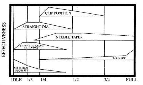
THROTTLE OPENING
Jetting Your Carb Circuits
To visualize how the various circuits overlap, please refer to the jetting chart. Always remember to change one carburetor component at a time and keep a record of your changes.
ZERO THROTTLE OPERATION (IDLE CIRCUIT)
IDLE SCREW:
Depending on your type of riding, adjust the minimum idle speed to desired RPM making sure the engine is up to operating temperature. If you do not desire any idle, make sure you turn in the adjusting screw just enough so the engine will not idle. This is especially important on Keihin PJ Series carbs in that the idle adjust knob (#4 in illustration) cannot be completely closed. Such an adjustment will result in a sluggish response off idle.
AIR/FUEL ADJUSTMENT SCREW:
The carburetor pictured in the exploded view uses an air adjustment screw (#5 in illustration) that is located upstream
of the throttle valve (slide) and meters air. Turning the air screw counter-clockwise leans the mixture off idle. Some carburetors have this screw located downstream
of the throttle valve, in which case, the screw meters fuel and opening the screw (counter-clockwise) results in a richer mixture. The idle screw usually has a range of one to two turns out from fully closed. If you need to adjust above or below this range, then the fuel jet will probably need to be replaced with a richer/leaner jet as required. Consult your owner's manual for the standard setting.
1/8 TO 1/4 THROTTLE
SLOW JET AND THROTTLE VALVE CUTAWAY:
Note - keep in mind that the idle adjust screw (air/fuel screw) gives a good indication of a properly sized slow jet (#6 in illustration). The slow jet calibrates the mixture from both the idle bypass and the idle orifice in the jet block. If the idle screw is properly adjusted, but the engine does not have good response when the throttle is wicked open, it is usually a sign of a lean mixture and the slow jet will need to be replaced with one size larger (richer) and the air/fuel screw re-adjusted. Consequently, if the throttle is only partially opened, such as in a trailing throttle situation, and the bike tends to load up, emitting a deep tone when the throttle is returned to full open, it is usually a sign of a rich slow jet. If the slow jet does not clean up this part of the circuit, the slide can be substituted for one with a different cutaway. The higher the number, the larger the cutaway will be, allowing more air to the jet block/nozzle screen leaning the mixture and, conversely, a smaller cutaway will richen the mixture with a greater effect up to 1/4 throttle.
1/4 TO 3/4 THROTTLE
JET NEEDLE:
The jet needle (#2 in illustration) is comprised of five major elements.
- Straight diameter section - In Keihin carburetors, either the last two digits or last letter denotes the diameter of the needle. The higher the last two digits, the leaner the needle and the lower the letter, the richer the needle. By going to a thinner needle, there is a larger area between the jet needle and the needle jet supplying a richer mixture.
- Length of the straight section - This determines at which point the needle taper will start relative to the clip position. If you have to run a needle in the highest clip position, a needle with a longer straight section should be used.
- Needle Clip Position - This works in conjunction with the length of the straight section. If the engine is too rich above 1/4 throttle, raising the needle clip (#1 in illustration) will lean the mixture.
- Needle Taper - A larger taper will result in a leaner mixture in the first half of the taper and a richer mixture in the last half of the needle. For example, a 1.34 taper will be richer in the first half and leaner in the second half of the taper than a 1.45 taper needle.
- Number of tapers - The needle can have one or more tapers; the number of tapers is not usually changed.
NEEDLE JET:
The needle jet/nozzle controls the fuel/air mixture up to 3/4 throttle. How it overlaps with the jet needle depends on the jet orifice inner diameter, air bleed holes and type of nozzle screen. Most modern Japanese carburetors use a fixed needle jet/nozzle assembly which cannot be removed. It your carburetor has a removable needle jet/nozzle, please contact the manufacturer in order to decipher the nozzle code. It is advisable not to calculate how rich/lean the needle jet is by using exclusively the nozzle inside diameter to needle outside diameter discharge area.
WIDE OPEN THROTTLE
MAIN JET:
The best track side method to determine the size of the main jet (#7 in illustration) is to fully load the engine on a long straightaway or hill. At the end of the stretch, chop the throttle and hit the kill button simultaneously. Now pull the spark plug. The parts of the plug you should be looking at are the positive electrode and last 1/4 of the ceramic insulator. Best power will usually result in a very light tan colored insulator tip and dark colored ring around the tip of the electrode. The electrode itself should have fairly sharp edges. For example, if the ceramic insulator has a nice tan coloring but the electrode has a white ring around the tip and the plug is of the correct heat range, then you can easily run a size larger on the main jet.
When jetting your main jet, try to remember to jet for the best power in a specific situation. As you gain experience and knowledge, you will be able to use other methods to determine your jetting. A good tuner can feel
most of the circuits by slowly reving a parked bike, or just by looking at the color of the unpainted pipe and silencer.