Site: Danish | English
Technical : The complex stuff - exciting but heavy reading, take your time.
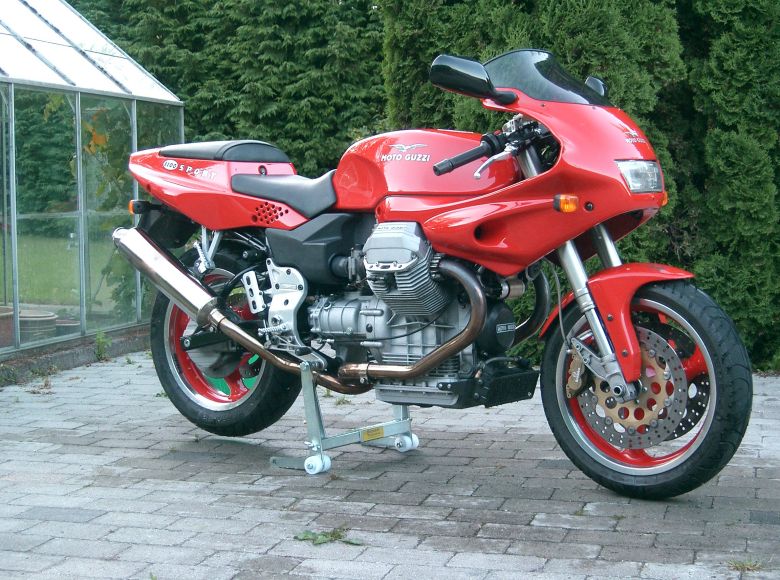
Jens Sport 1100i
Pictures from Nordic Guzzi meeting 2005
Please contact Gregory Bender with any questions, corrections, or suggestions for improvement.
Gallery
Jens Sport 1100i
Table of contents
- Have a look - my "new" Sport 1100i.
- Modifications (2005 - 2007) Gearbox.
- Modifications (2005 - 2007) MY16M ECU
- Modifications (2005 - 2007) Bevel box.
- Modifications (2005 - 2007) Roper Sloppage sheet
- Modifications (2005 - 2007) Luggage.
- Modifications (2005 - 2007) Brackets for Givi luggage rack.
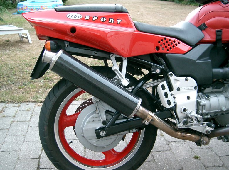
- Modifications (2005 - 2007) Carbon fiber cans.
- Modifications (2005 - 2007) Brembo PSC16 Master cylinder
- Modifications (2005 - 2007) Hydraulic Clutch
- Modifications (2005 - 2007) Pazzo Levers
- Modifications (2005 - 2007) Mirrors
- Modifications (2005 - 2007) LED turn signals
- Modifications (2005 - 2007) Throttle lock
- Modifications (2005 - 2007) Decoration
- Modifications (2005 - 2007) Oil filter tool
- Modifications (2005 - 2007) GPS
- Modifications (2005 - 2007) Immobilizer
- Modifications (2005 - 2007) Misc. small mods
- Modifications (2008) TomTom Rider 2 GPS
- Modifications (2008) My16M Mk3 ECU
- Modifications (2008) Carbon fibre valve covers
- Modifications (2008) Choke lever
- Modifications (2008) LED rear light
- Modifications (2008) HID Bi-Xenon head light
- Modifications (2008) Inside coating of gas tank
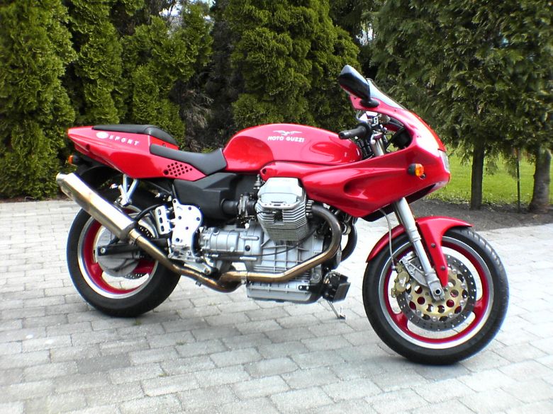
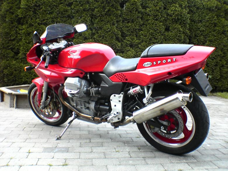
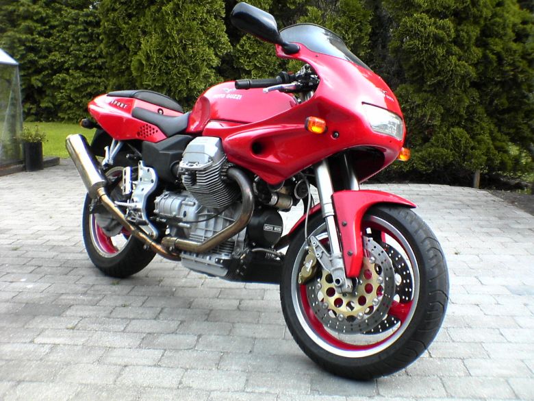
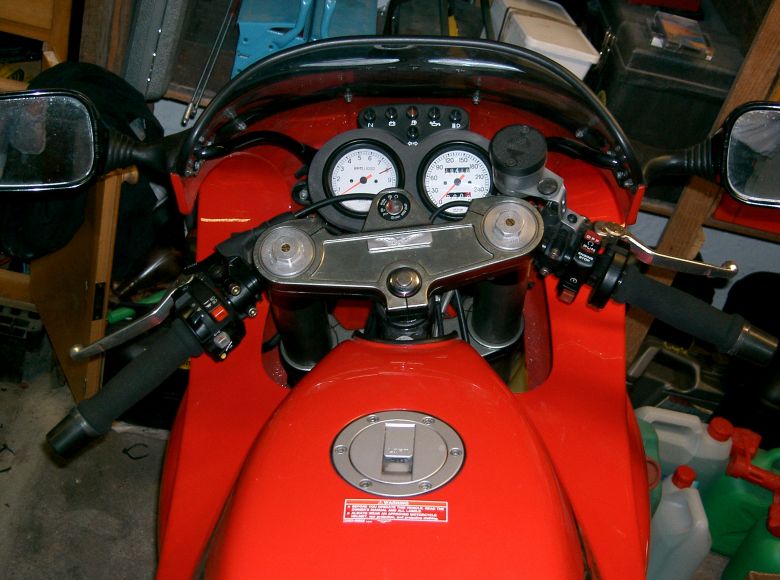
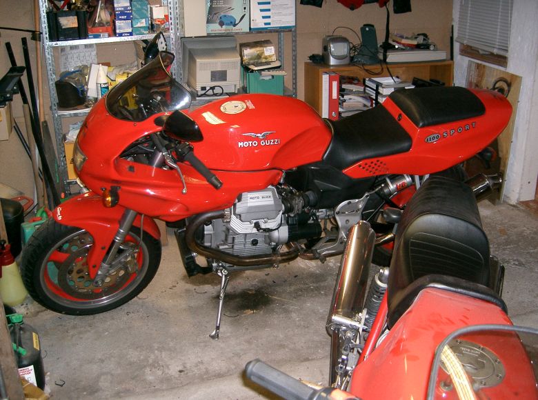
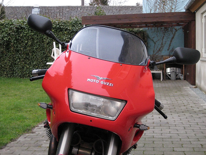
Have a look - my "new" Sport 1100i.
I've wanted one of these since they first arrived on the market during 1995/96. It took 8 years before it was within realistic economical reach, and even though I was extremely pleased with my Le Mans I decided to change.
I found my new bike in Germany with less than 20.000 kms on it, and two previous owners (both above 40 years of age). All original except for a Stucchi cross-over.
It looked very nice, a little dusty as it had been stored in the show room for 6 months, but obviously a virgin: Engine had never been taken apart, and no one had tampered with it. This means that you don't have to correct other peoples errors, that means apart from the errors made by the factory!!!
For even though its a 20 years newer construction, it still have the Italian heritage: The owner still have to finish a number of details to make the bike what it should have been from the factory. Details about this in the box below.
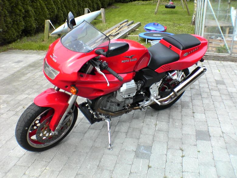
What's it like, then ?
Absolutely amazing is not a very detailed answer, so I'll try to be more specific in the following:
- Riding position - more sporty (stretched) than on the Le Mans. A lot of weight on your hands in city traffic, but nicely balanced from 100 kmh and upwards.
- Fairing - covering you nicely, wind pressure on your helmet, but no turbulence.
- Steering - quicker than the Le Mans, but just as stable. An easy ride, and as soon as its rolling you dont feel the weight.
- Suspension - Worlds apart, this one actually works. You're an easy victim when your previous bike was a 20 years old Le Mans whish is hard as a rock, but still: Its obvious that this one is a modern construction (suspension vise) and that quality components has been used. Very nice on the bumpy back roads.
- Brakes - top note! 320mm Discs and four pot Brembo Calipers are state-of-the-art equipment for Italian sports bikes.
- Engine - not that different from my modified Le Mans. It pulls more willingly between 6 and 8 thousand RPM, but feels otherwise more or less the same. The travel of the throttle is only approx. 60% compared to bikes with 40 mm Dell Orto's. This means that you are going really fast when you wind on the throttle as you are used to. A significant psychological effect, really.
- Gearbox - business as usual. This one has a somewhat higer gearing, which meant that I had to change my gear changing pattern, but after a couple of days I had the hang of it.
- Fun factor - the most important measurement: That's how happy you are after a ride. The scoring here is Five stars plus bells and whistles......
/Jens
Modifications (2005 - 2007) Gearbox.
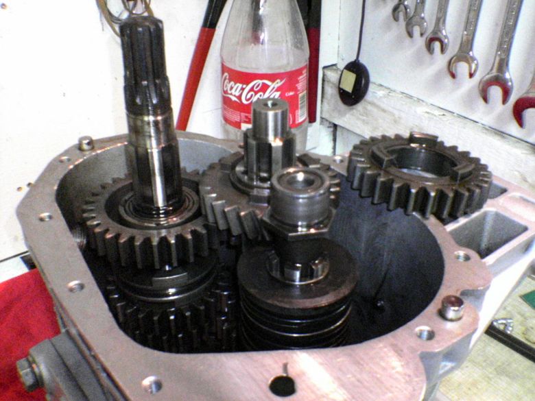
As mentioned earlier, you'll probably not be a happy Guzzi owner before you have sorted the bike properly, and owning a 1100 Sport is no exception here: Most 1100 Sport are made with straight cut gearwheels and other owners experiences have shown that the 5. gear is not strong enough for the power available. Its a bomb waiting to blow!! In most of these bikes the fifth gear loses the surface hardening of teeth's before the bike has done 50.000 kms. You'll note it by the increased amount of metal parts on the magnet in the drain plug, and the horrible whining from the gearbox in 5 gear. This makes a quick repair necessary if you want to avoid a complete blow up of the box (you definitely do).
Mine was whining and had plenty of metallic crud
Luckily the last of the Sport 1100i's had helical cut gear wheels, so in theory you just order a set of helical cut 5 gear wheels and build them into your gearbox (First to fourth gear will usually be OK, its just the 5. gear that self destroys). Italian spare parts logistics doesn't help you here: Helical cut gear wheels was not available from the factory, and no one knew when a new batch was being made. So I made a (large) number of phone calls to European Guzzi dealers, and finally I tracked down a set of gear wheels at Agostini in Mandello Del Lario - right next to the factory !
Modifications (2005 - 2007) MY16M ECU
When you're not satisfied with the performance of the Weber Marelli 16M ECU, you have a number of opportunities:
- Adjust TPS, low range mixture pot-meter, bypass valves, and balance till you drop.
- Install an extra black box (Power Commander or equivalent) to alter the injection signal, and maybe the ignition timing.

I tried the adjustment fix, but I was never quite satisfied with the result, it still had the occasional misfire at 3500-4000 RPM, and the idle was never as stable as on my old Le Mans with 40mm Dell Orto's.
Another EPROM is a quick and cheap thing to try, but you simply don't know what you get. You have to be very naive to think that just because the little black bug is named (High Speed Tuning Chip) it'll solve all your problems. And even if it does work to your satisfaction, its no good any more if you install the loud carbon cans, or throw in another cam, or..... The EPROM way didn't seem to be the solution to me.
The Power Commander was actually considered as its a well known product, doing a lot of good for a lot of bikes. The only negative side is that installing a Power Commander, gives you an extra black box that's hard to diagnose if your bike is acting up, and absolutely impossible to repair on your own. This is an important issue to me as I was having several considerations about buying a F.I. bike - I do not fancy black boxes, I like to be able to fix my bike my self. (Yep, I'm a stubborn, old fashioned fundamentalist)
As for third party ECU's (Only Weber Marelli 16M), I already knew about two suppliers (Moto Spezial, and HT Moto. Both German). Unfortuneatly both were very expensive and absolutely out of financial range. Period.
Hang on, I'm getting to the point now!! On one of the Moto Guzzi forums, I learned about the My16M ECU, developed in Australia by Cliff Jefferies (check out his web-site).
Now, this was interesting - every one was praising the My16M, and it had a very comprehensive set of features:
- It will fit into an original WM16M box (providing you remove the original PCboard) - this means that you don't have to alter the original wiring, and you can keep the original WM box as a spare if you prefer.
- You can buy it assembled or as a kit - hardware is open, allowing you to fix it yourself if it breaks.
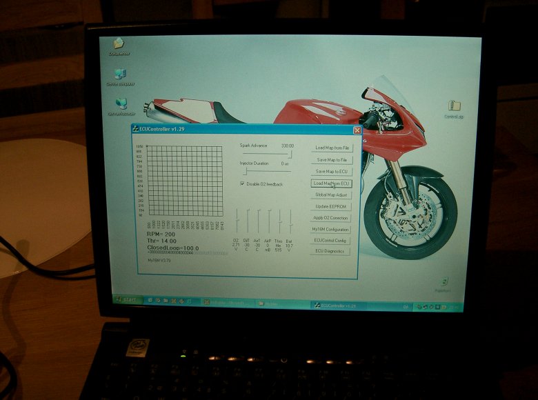
- All parameters can be changed with a PC program and a standard RJ45 network cable. Maps are stored as files on the PC and can be loaded into the ECU quickly.
- You can even change maps while riding using the optional Optimizer box.
- Diagnostics tool allows you to check the input of all sensors.
- Install an O2 sensor (Narrow or wide band), and let the ECU go closed loop. (Automatic change of mixture depending on feed back from O2 sensor)
OK, you guessed it, I bought the kit + optimizer + a dead WM16M ECU from eBay.
Depending on your electronic skills, building a kit like this may be easy to you, but to me it was a real challenge. I have a technical education that included some electronic knowledge, but I haven't done any soldering the last 15 years.
I'm aware that most failures in electronic equipment is due to mechanical stress, so I used very much time to make everything fit properly into the boxes.
I had a few problems building the kit, mainly due to the information on Cliffs web site not showing the latest version, but Cliff provided excellent and fast support on all my questions.
After finishing the My16M and optimiser kit, I had the bike started a few times, and everything seemed to work. But it was still winter in Denmark, and I had to show a little patience for a couple of month, before I could start testing/tuning.
From narrow band to wide band sensor.
I finished the assembly of the bike, had a friend of mine welding a stainless bung for the O2 Sensor into the right header pipe, and installed the O2 sensor. After starting the bike a few more times, it was obvious that the cheap narrow band sensor was far too digital in behavior to be of any real use. So I decided to go wide-band and started the search for the right product. My choice was the LC-1 unit from Innovate motorsports (Europeans should buy from German LM-1.com for better prices and excellent support)
The narrow band sensor will connect directly to the My16M, but the wide band unit is a bit more complicated. It consists of the sensor, a programmable controller unit, and few external items (pushbutton, and LED for calibration and error codes).
I had to find a location for the controller, and found out that it would fit under the seat, but only if I angled and tilted it just right. An aluminum bracket was made and I managed to squeeze the controller in place. This may sound easy, but it took several hours to get the bracket right.
The controller had quite a few wires (power, three grounding wires, programming, calibration, and two outputs), so I made up a small distribution box for wires, buttons and the LED. To be sure that the wires was properly connected, I soldered all wires to a small PC board in the box.
The LC-1 powered up, and I programmed the two outputs with no trouble at all. I really like the LC-1 unit - it works as it's supposed to and easy to set up.
Tuning sessions.
Finally, spring arrived in Denmark. I took the bike out started it, and synchronized the throttles. Ready to rock.
The bike was now smoother and much more pleasant in behavior than with the original WM box. That is, above 2000 RPM. It was really weird at idle: Sometimes it was fine, at other times it could cough and puff, or simply just stall. After a few days of belly scratching I finally found out why - inlet rubber manifolds not tightened properly !!! (Do not mention this to me - ever ! I'm a bit touchy on this subject.....)
During the first days of testing I made a few unintended adjustments while playing with the Optimiser, but with a little experience, I got the hang of it. No problem now.
Now the idle was stable once obtained, but if I just snapped the throttle closed from speed, the bike would stall every time. In other words, I had to "guide" the engine down to idle. After a few experiments, I found out that leaning the bottom row of the map about 10% did the trick.
So all in all, the My16M-optimiser-LC1 combo reacts nicely and correct to my changes in mapping, the challenge for me is now to learn which parameter to change to get the desired effect, and finding the right O2 targets for closed loop operation (I already run closed loop, but I'm not positively sure my O2 targets are correct).
For the first test rides, I brought the original WM ECU in a tank bag - just in case. But the My16M has been 100% stable from day one, so the WM box remains in my workshop now.
I still have a lot of testing and fine tuning to do, but I'm very, very satisfied with the performance of the My16M. And the pose value of the Optimiser box is tremendous :-)
After 3 month.
I've done a number of small adjustments, and the result is even better now. With the original WM-ECU, I could go no lower than approx. 3500 RPM in top gear, now I can go all the way down to 2000 if I'm easy on the throttle. Not that I do this much, but it gives you an idea of the improvement in drivability.
I'm still playing around with settings, just for the fun of it, but my base map haven't changed mush the last couple of month. I haven't had any problems at all regarding stability or weird drop outs, so I'm still very very satisfied with the My16M + Optimiser + LC1 combo.
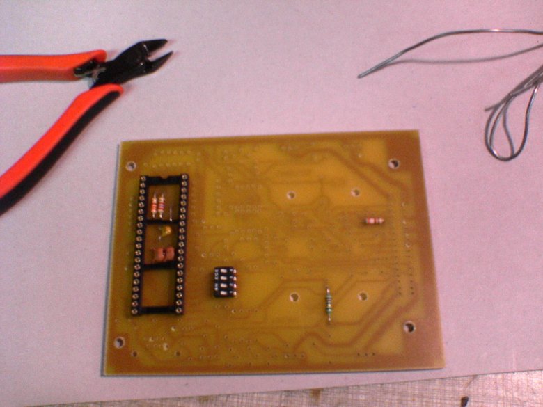
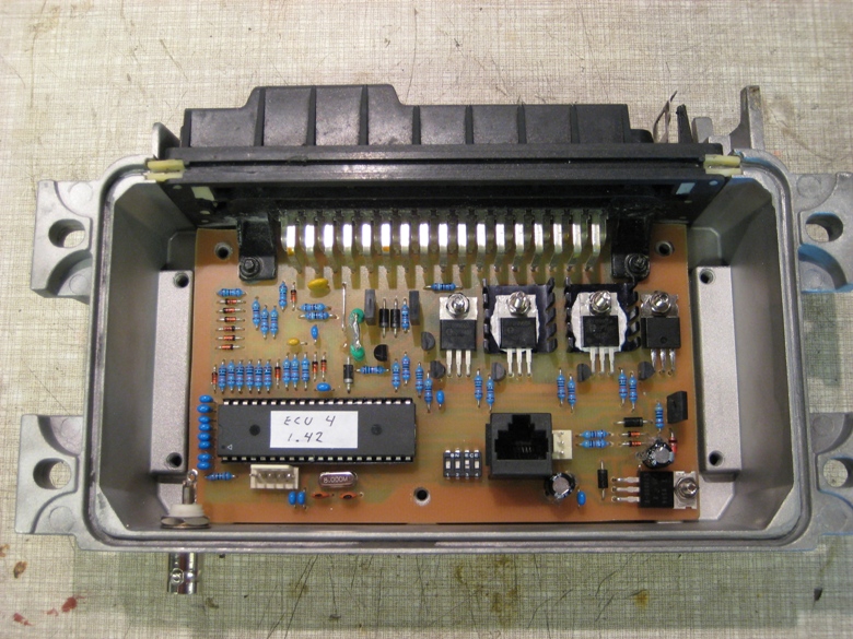
Building the My16M and accessories - the pics.
Pictures below will show the progress of building the My16M ECU, Optimizer, and LC-1 wideband sensor unit. Sorry for the quality of the pics, my cell phone camera is not that good for close-ups.
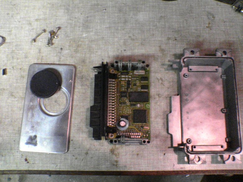
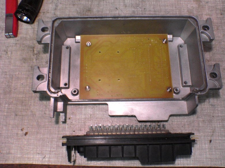
Dismantling dead Weber Marelli box (from a Ducati 916)
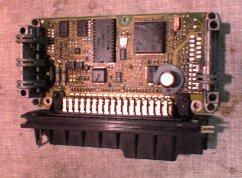
WM16M print
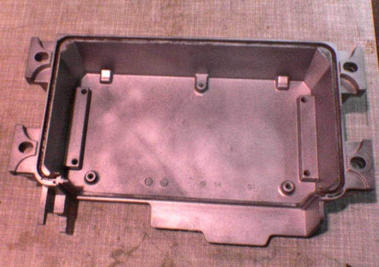
Bare box
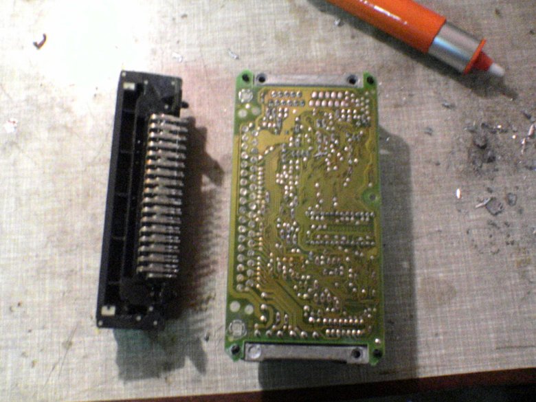
Print and connector separated - connector can not be bought separately.
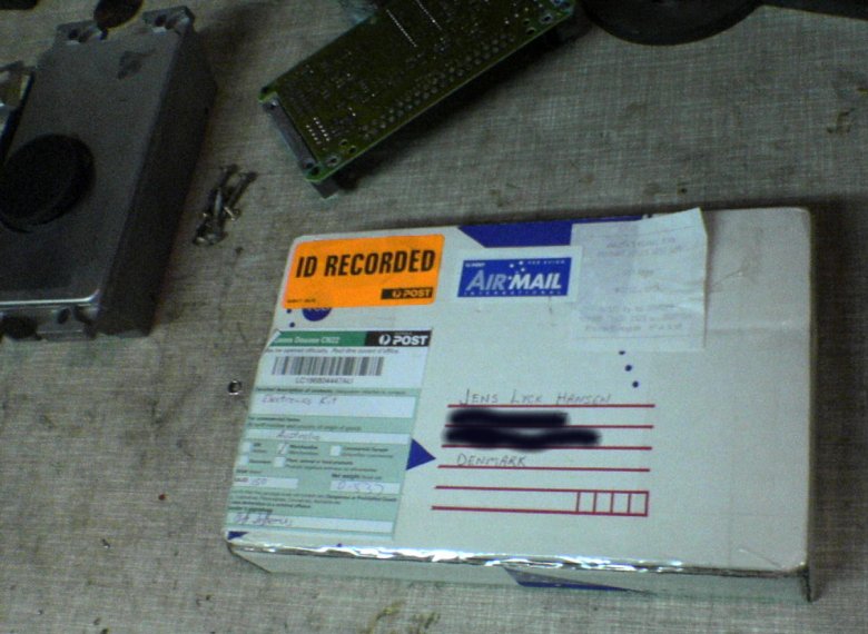
Kit arrives from Australia - Guess if I'm exited.
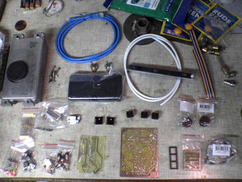
Content of package - having second thoughts on this project.
First fitting of PC-board to box.
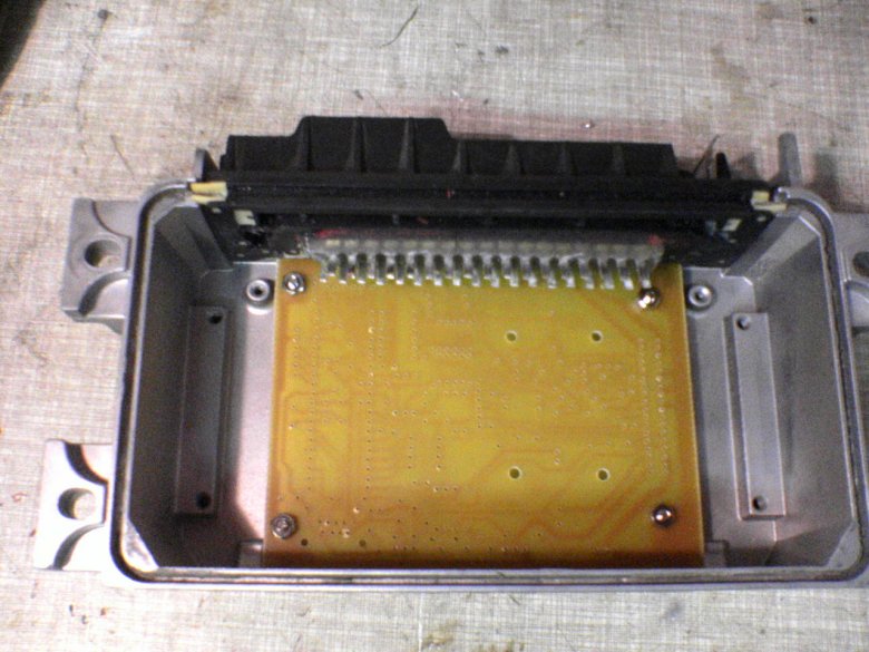
Check if there's still room for the connector - note connector pins cast into epoxy glue to avoid breaking.
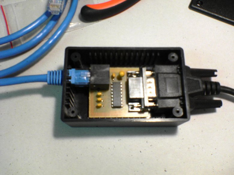
RS232 board for PC connection soldered and boxed.
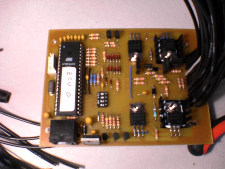
Soldering main PC board.
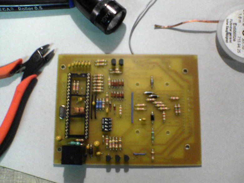
Still soldering.

Will the connector still fit when all components are installed ?
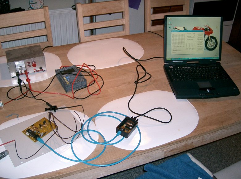
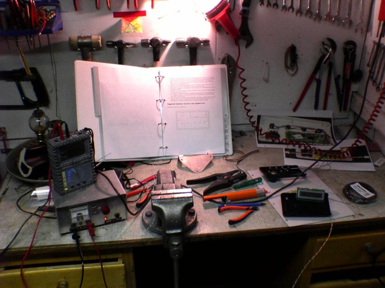
First communications test (Wife not at home).
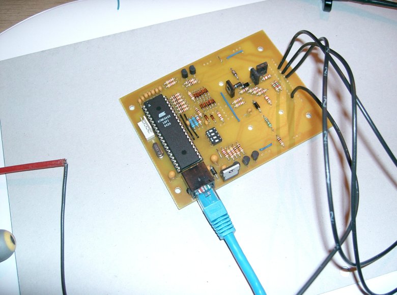
RJ45 cable and the necessary wires fitted ....
and we have communication :-)
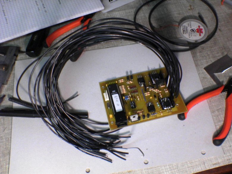
Lots of wires.
not much room.
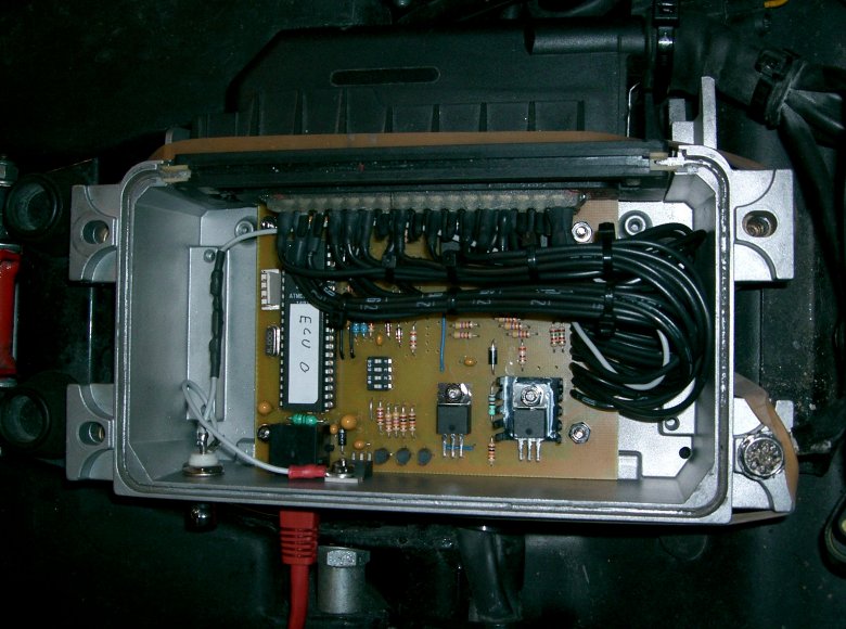
But with a little patience everything fits nicely into the box. Note BNC connector to the left for O2 Sensor.
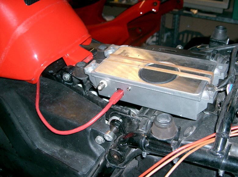
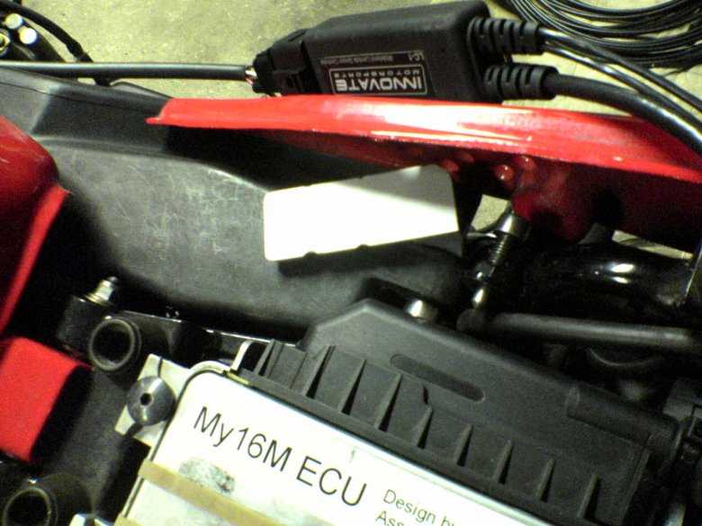
My16M installed to the bike, and it started right away..... This is actually a later picture with the RJ45 cable for the optimizer in place
Building the Optimizer.
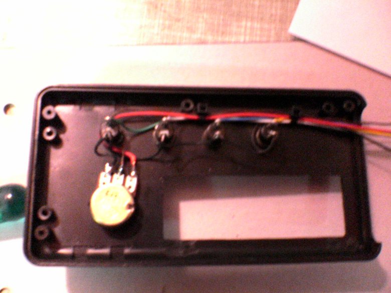
Wiring buttons and potentiometer. Actually, modifying the plastic box for the optimizer involved a lot of time and belly scratching - I think the box was designed for a remote control.
First power up of the Optimizer - Proud of myself again.
Optimizer fitted to the bike.
Nice little bracket, ehh ?
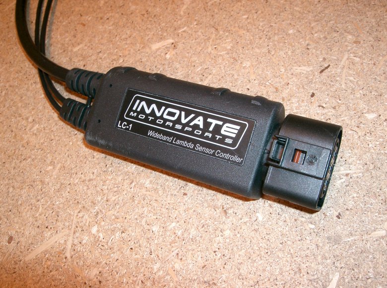
LC-1 wideband controller.
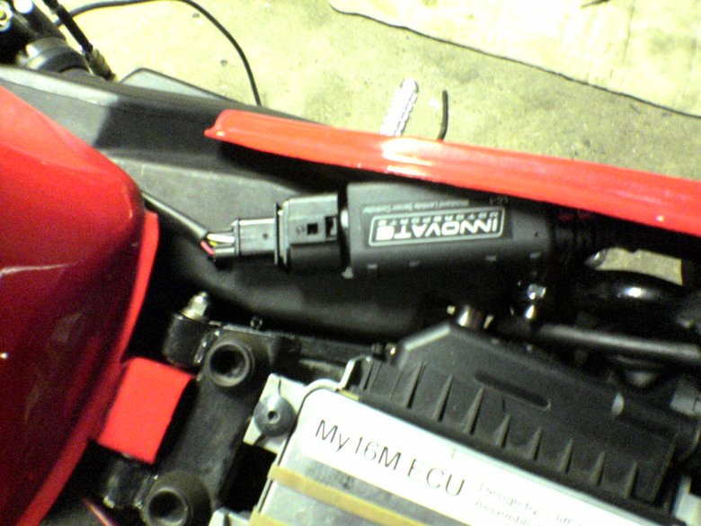
Will probably fit in here....
... if I tilt, angle, and bend this little bracket for a couple of hours !!!
Yep, I'm proud - even the seat fits now :-)
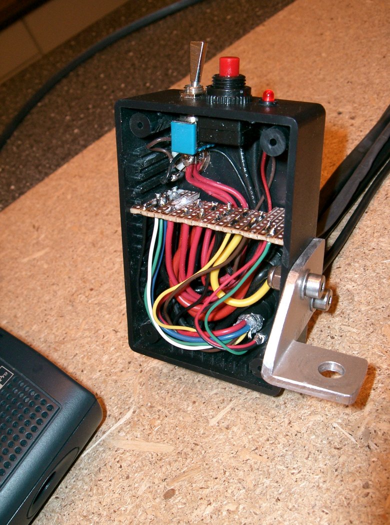
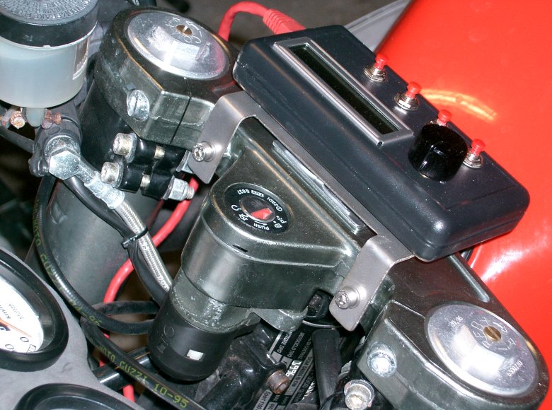
Power/signal distribution box for wideband controller. LED for error codes, pushbutton for calibration, and toggle switch for choice of power supply (one for calibration, one for normal running).
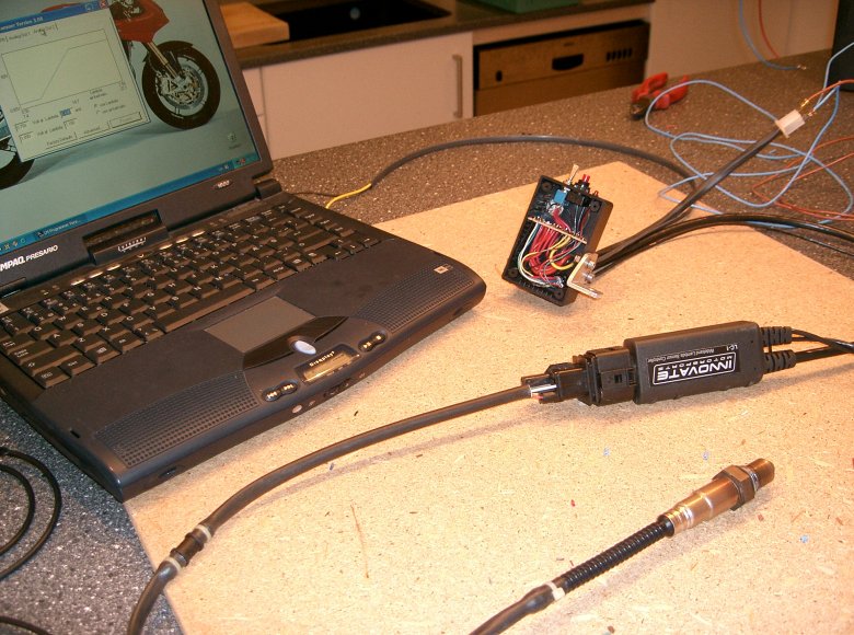
Sensor, controller, and distribution box in test setup.
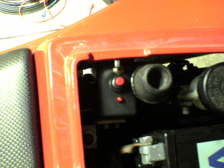
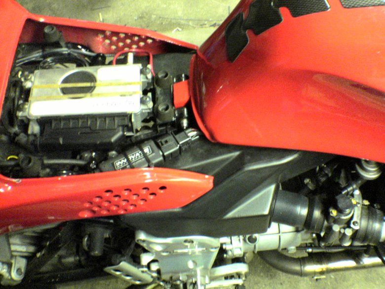
Distribution box installed under rear seat.
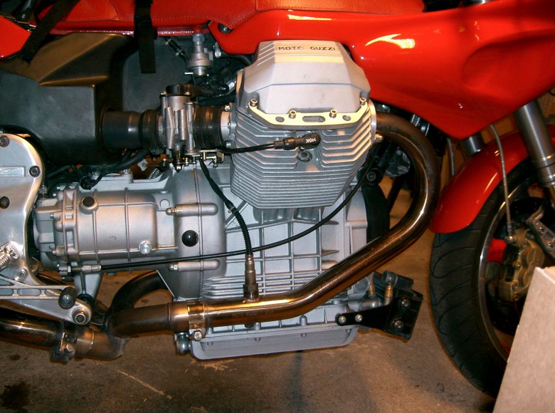
Location of O2 sensor.
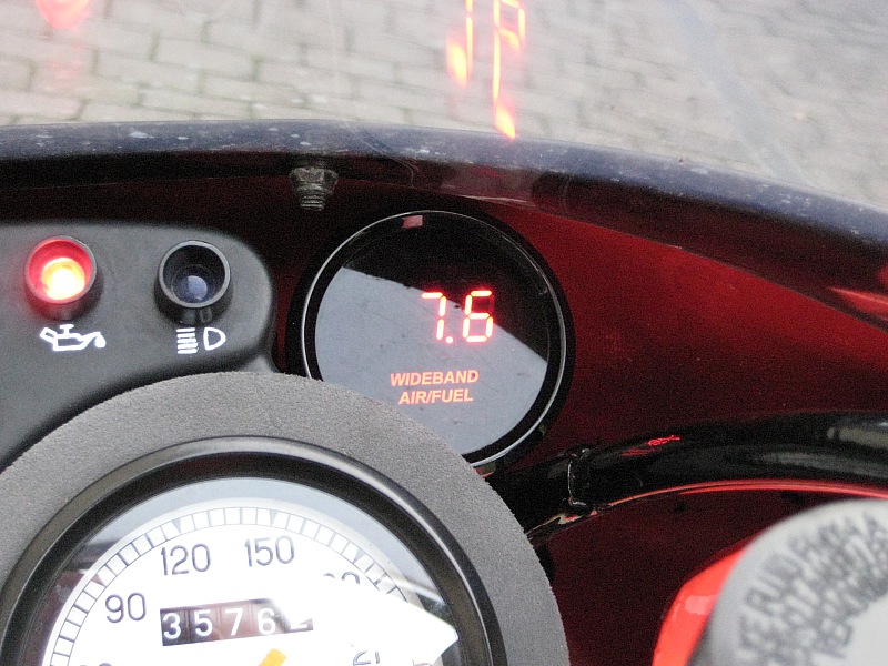
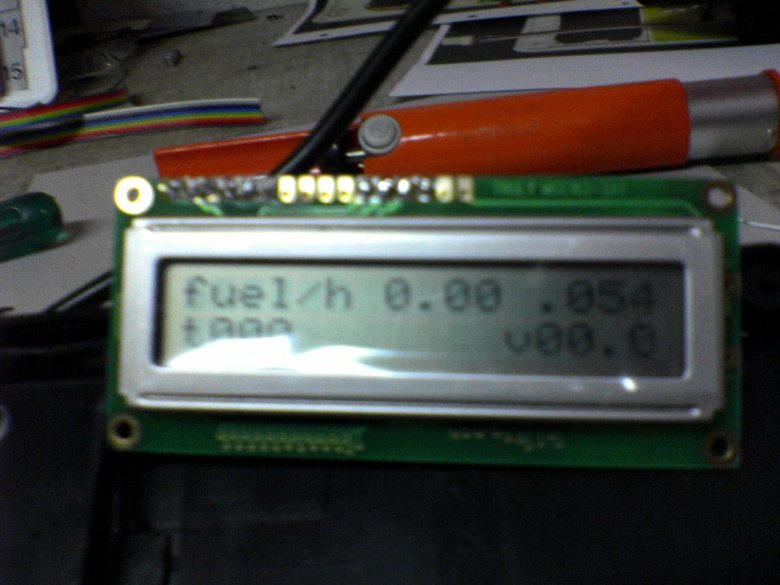
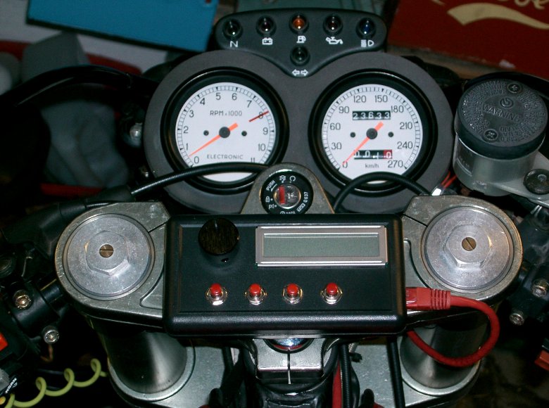
Latest addition to the MY16M project is an air/fuel meter to allow me to follow the mixture ratio at all times.
Modifications (2005 - 2007) Bevel box.
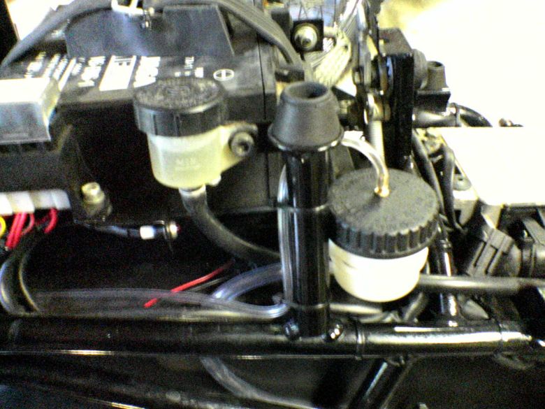
When Guzzi reinvented the open shaft drive (to be able to run wide rear tires), the air volume in the bevel box is no longer sufficient to cope with the increased air pressure when the gear oil heats up. This means that the oil will be pressed through the big seal and end on the rear wheel.
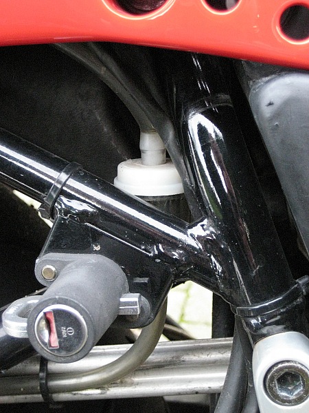
The solution is to establish some kind of wenting to allow the hot air to escape the box. I drilled out the ball from a grease nipple and installed it into the filling plug. Then I ran a piece of plastic tube from the nipple to a spare brake fluid reservoir under the rear seat. I haven't seen oil on the rear wheel since :-)
Second try
After longer periods of high speed riding, the rear drive could still press oil all the way through my new venting system, probably because I have used tubes of too small diameter. But a friend in Austria modified an industrial hydraulics venting cap, to fit his Guzzi - and he could be talked into making one for me too.
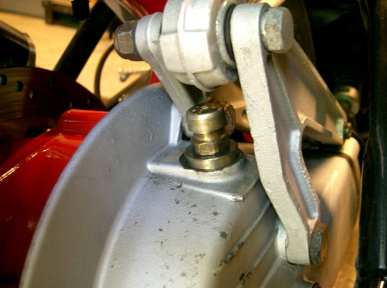
Its better than the first setup, but I still see oil being pushed out when using the bike hard. I'm wearing my thinking hat for the final solution.
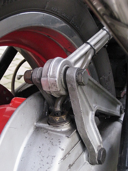
Third time - succes !!
Back to the tube solution - this time with a larger diameter tube. This seemed OK the first times I rode the bike, but on rare occasions I could still make it press oil out. (A few drips can really make the bike look messy).
The solution was to combine the large diameter tube with a cheap plastic fuel filter. Rear end has been clean for 6 months now :-)
Modifications (2005 - 2007) Roper Sloppage sheet
If you need to know why and how, click here and here
Modifications (2005 - 2007) Luggage.
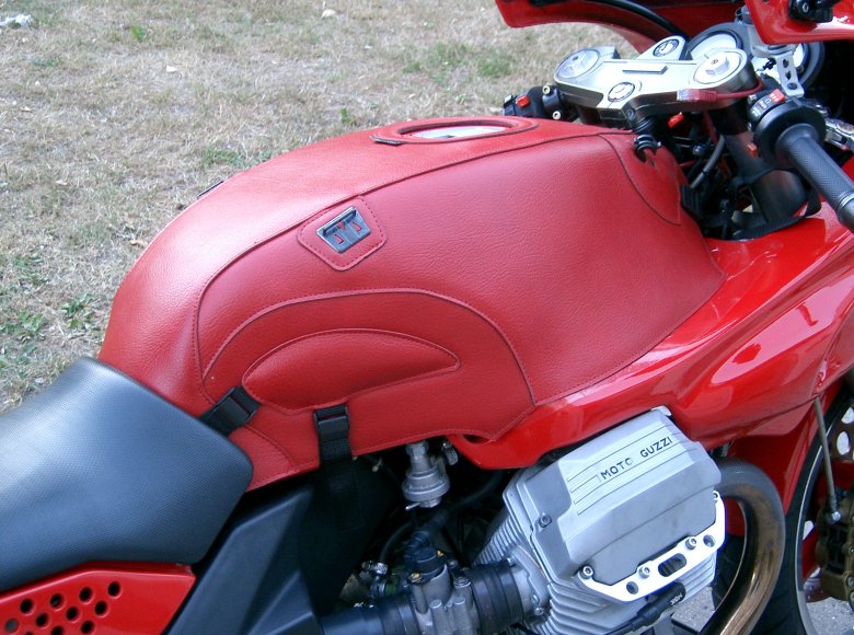
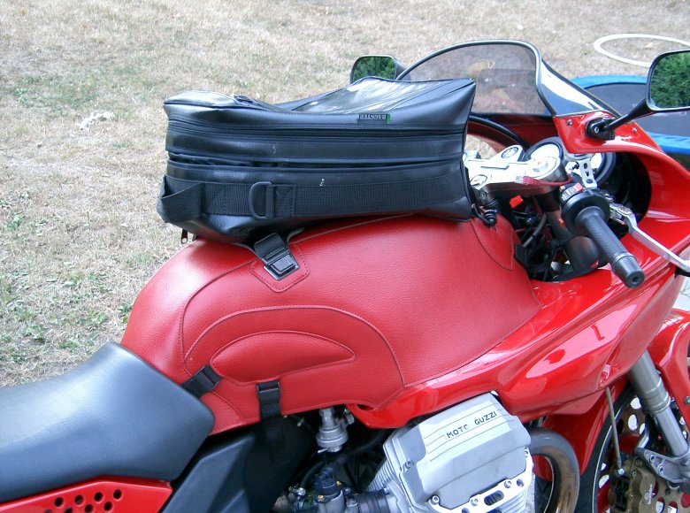
Bagster makes the best tank bags - because of the model specific tank covers in correct shape and color. As the 1100 Sport went out of production 7 years ago, the tank cover is naturally not in production any more, but I did manage to find one at the British importer. A brand new tank bag for the cover was bought on eBay in Germany.
Only real problem with the Bagster was the installation time of the cover. It took me only 10 minutes to do this, but it was enough to annoy me when I had to do this for every day trip. Leaving the cover on for ever is NOT an option for me.........
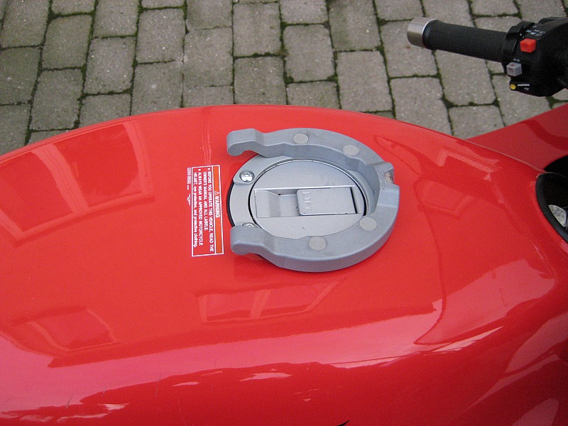
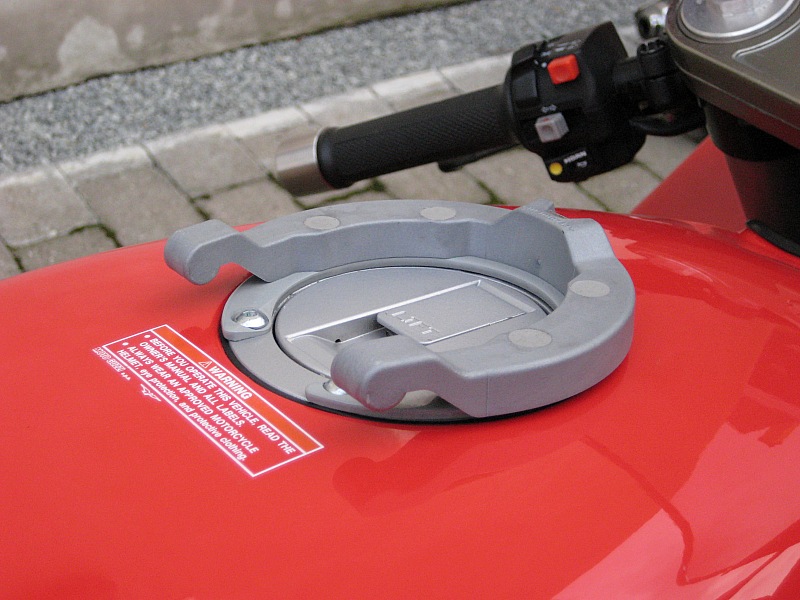
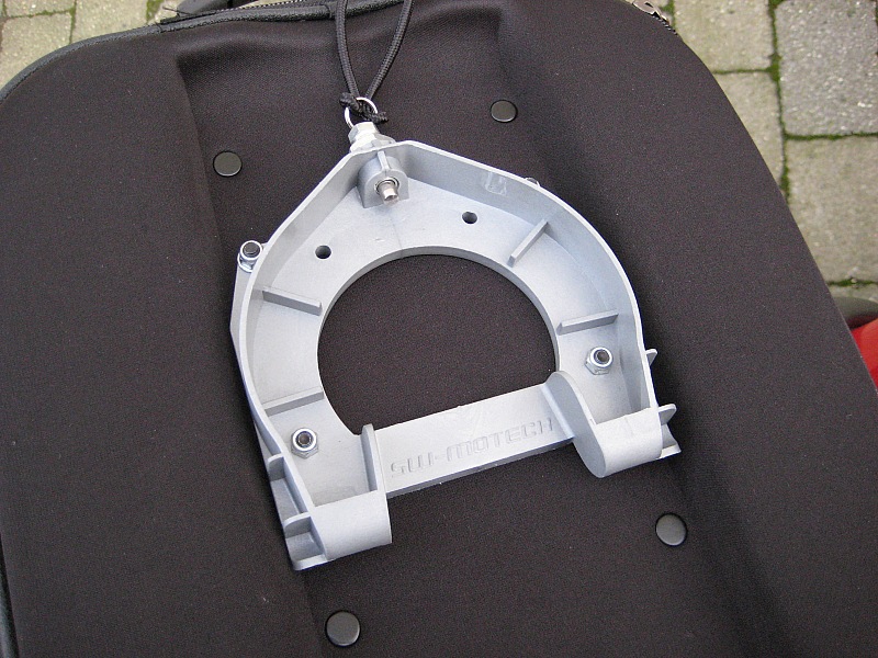
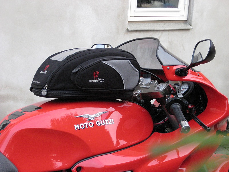
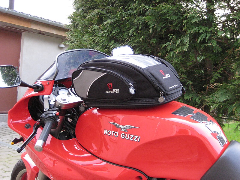
So when I saw the SW-Motech tank bag system that just clicks on to a bracket that is installed on the tank filler, I knew that this was the right solution for me. The Bagster system is sold and I'm very satisfied with my new tank bag.

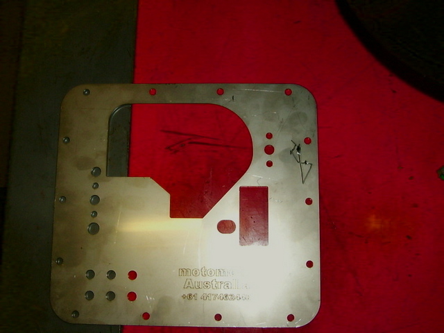
Next I bought a spare rear seat, where I installed a base plate (own design, laser cut stainless) for a GIVI topbox. Rear seats can be exchanged within 10 seconds.
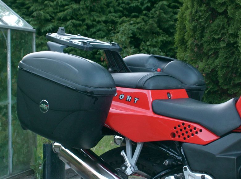
For weekends and holyday use with a pillion passenger, there's a need to haul more luggage. It really doesn't add to the overall look of the bike, but is necessary when you don't want a Goldwing-like motorcycle.. It's no easy task to add a luggage rack to a 1100 Sport, and no one is making anything model specific. But after a couple of weeks belly-scratching, I managed to invent a set of brackets. Now its possible to install/detach the luggage rack in less than five minutes, and the small brackets that are permanently installed on the bike are almost invincible.
Several people have asked for detailed instructions on how to build the brackets, so I made a description and a few pictures available here.
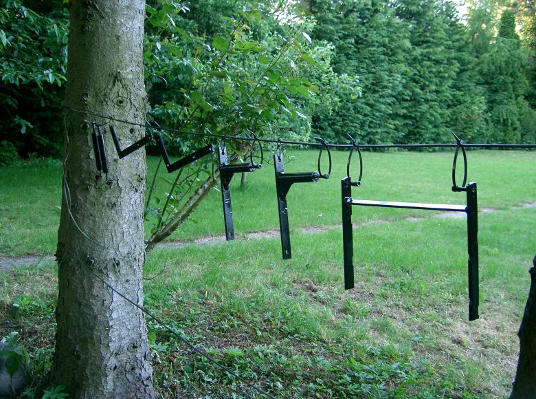
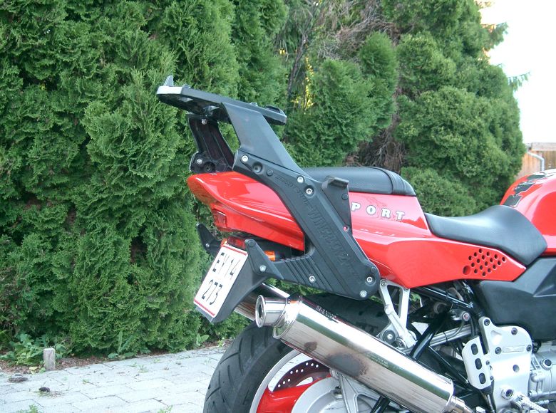
Modifications (2005 - 2007) Brackets for Givi luggage rack.
Fitting the Givi was really a pain in the butt, and it took several weeks of thinking (I'm not that bright) before I came up with a solution.
The brackets are in two parts, one part that's permanently fitted to my bike, and one that is fitted to the wingrack. So now, installing the wingrack is done by 4 allen screws (a 5 minute job). The wingrack is located pretty far from the center of the bike, due the rather wide tail of the bike, but as long as the topcase plate is tightened properly, the rack is actually pretty stable. Note the small reinforcement on the bracket for the wingrack, don't omit it – all weight is carried in this point.
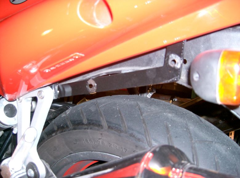
The bracket that is permanently installed to the bike is the hard one to make. It consists of three parts: Two brackets (one on each side of the bike) and a large H-shaped bracket located under the rear seat.
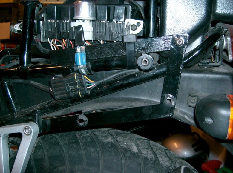
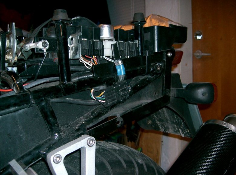
The smaller visible side brackets (the one from the top picture) is mounted in the passenger foot rest bracket and to the H-shaped bracket.
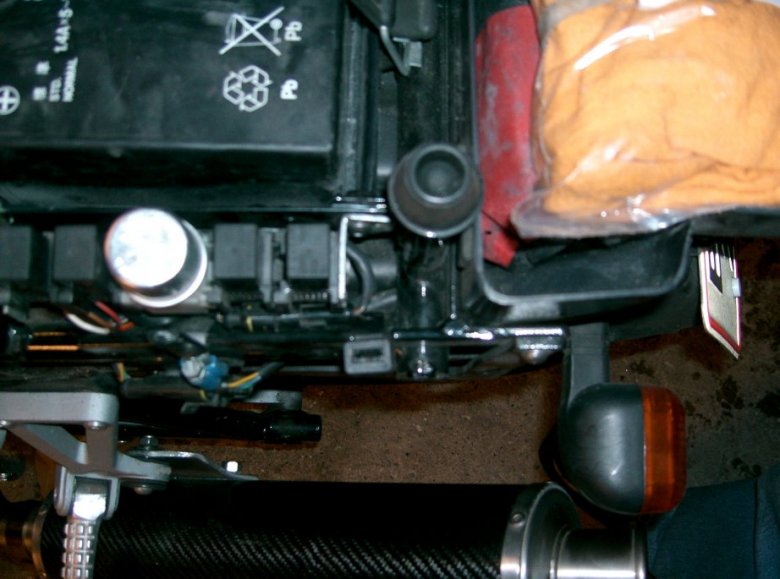
The H-shaped bracket is made from 5x20mm flat steel. Two bars are running on top of the rear frame tubes just under the rear seat, right next to the relays on the left and the fuse box on the right. The center bar of the H is located between the front of the tool box compartment and the two rear studs that holds the rear seat. You probably have to take the tool box compartment out to squeeze the bar in. when everything fits nicely, you weld the three bars into a “H”, be very careful to be precise, there's no room for mistakes (Note that no welding at all is done on the bike, all brackets are detachable.)
Now, the rear ends of the H-bracket are drilled and a M6 thread is cut to be used as rear mounting point for the two small visible brackets. The front end of the “H” is secured to the rear frame tubes on which the bracket stands. I used steel ties (I don't have the right word for them, but they are the ones you use to tighten a hose to a stud, and you tighten them with a screwdriver.) Be very careful to avoid destroying the wiring which is located nearby.
Its a tight fit and a hell of a job, but if you take your time the result is pretty good. I've seen other home made brackets for the Givi / Guzzi 1100 sport combo, but most of them looks like shit. This one is almost invisible when the wingrack is not installed, and stable at +200 km/h (almost allowed in Denmark when you're riding a beautiful Italian motorcycle).
Modifications (2005 - 2007) Carbon fiber cans.
Modifications (2005 - 2007) Brembo PSC16 Master cylinder
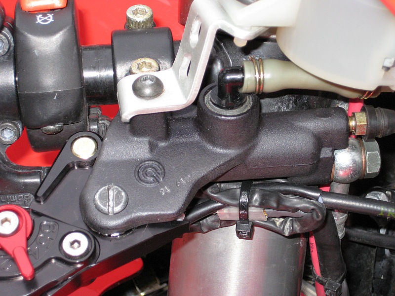
I was never satisfied with the spongy feeling of the original PS16 Master cylinder, so I installed the newer and upgraded PCS16.
Recommended !
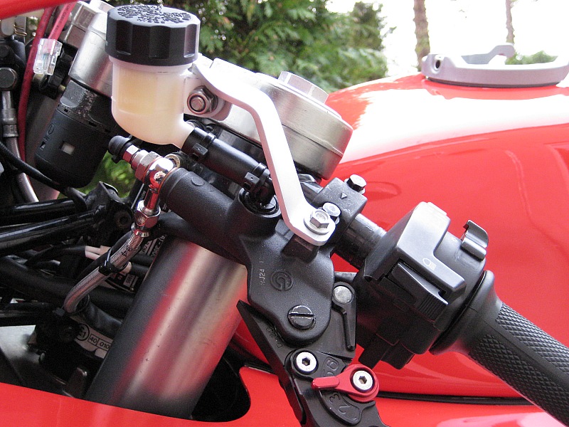
Modifications (2005 - 2007) Hydraulic Clutch
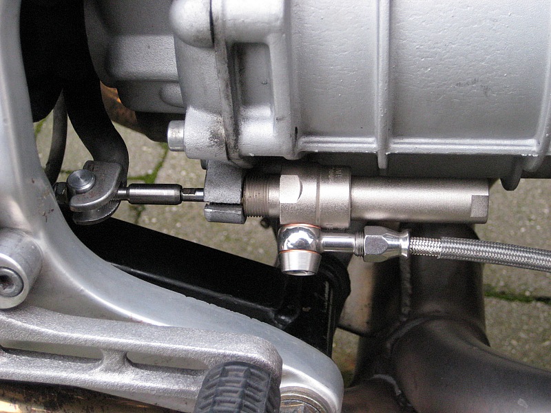
Why? - Don't even ask.
The main reason is actually that I discovered that the beautiful Pazzo levers was available for the PSC16 brake master, but not for the cable actuated clutch.......
So I thought of making a hydraulic conversion as a winter project - just to be able to get the Pazzo's. I've always thought that hydraulic clutches on bikes was technology without reason, but as few people have had success with a conversion like this, there was also a degree of challenge in the project.
First I bought a Brembo clutch master cylinder (The equivalent of the PSC16 to fit the Pazzo's) and a slave cylinder from Guzzitech.com. I heard different rumors about this cylinder - most people complaining about the stroke being insufficient to release the clutch fully. But as usual, I'm a wise smart-ass, and I was sure that everybody else was unable to bleed the cylinder properly......
Much to my surprise, I experienced the same thing as everyone else, and the stroke of the slave cylinder was only 5,5mm (with the master cylinder I just bought - an other diameter master will give a different result).
The stroke from the cable actuation was 10,5mm, so it was obvious that this master/slave combination would never work for me. It may "work" if I'd adjust it very carefully, but I would have a very light clutch that would need full lever travel to disengage. What I want is precise and fast control - not a light and slow clutch.
I did a few calculations to determine the proper cylinder diameter to give me the stroke I wanted, and I managed to find an industrial cylinder in Switzerland that would provide me with a stroke of approx. 10,3mm. A friend with a lathe did a few necessary modifications to the cylinder, and I could finally put everything together.
Oh yes - please also check the aluminum bracket for the hydraulic fluid container - I did that one myself :-)
The result is a lot better than I could ever imagine - remember that I never saw the need for an improvement. Operation of the clutch is much more precise now. Engagement point is now crystal clear where it could be a bit "wooley" with the cable clutch. The lever force is more or less the same, I cant really feel the difference.
Modifications (2005 - 2007) Pazzo Levers
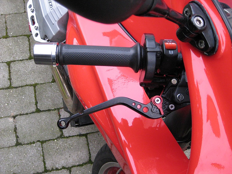
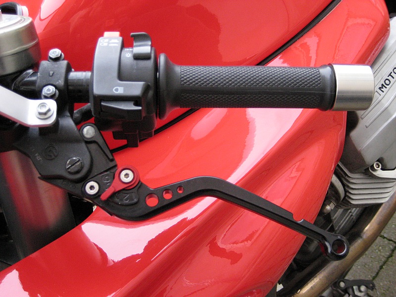
No need for fancy words here - its a real quality upgrade!
Modifications (2005 - 2007) Mirrors
Original mirrors are last century style, and have a nasty habit of folding when you ride fast (Easy to do on this bike)
The solution was a set of aftermarket mirrors originally designed for Honda CBR600F4/VTR1000SP1. They fit perfectly when you rotate the mounting bracket 180 degrees - a five minute job.
And even better - they are spaced a little wider, allowing you to see more than your own shoulders......
Modifications (2005 - 2007) LED turn signals
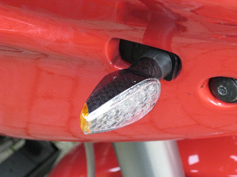
I was tired of changing bulbs that was broken due to vibrations, so I bought a set of LED turn signals.
You need to install an electronic flasher relay and two diodes for the warning light in the dashboard, but the new turn signal lights look really good on the bike, so it's worth the effort.
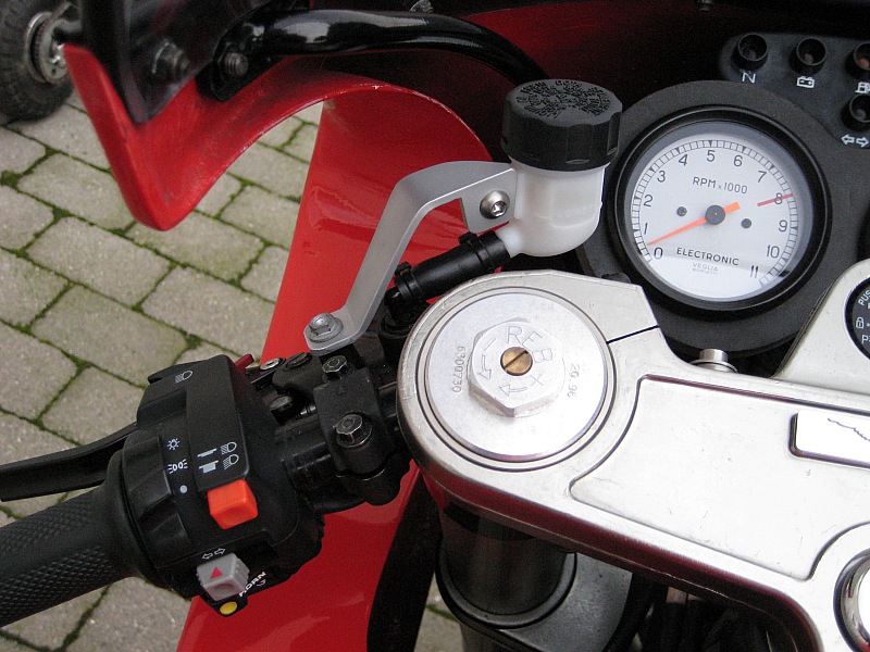
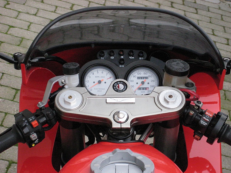
Modifications (2005 - 2007) Throttle lock
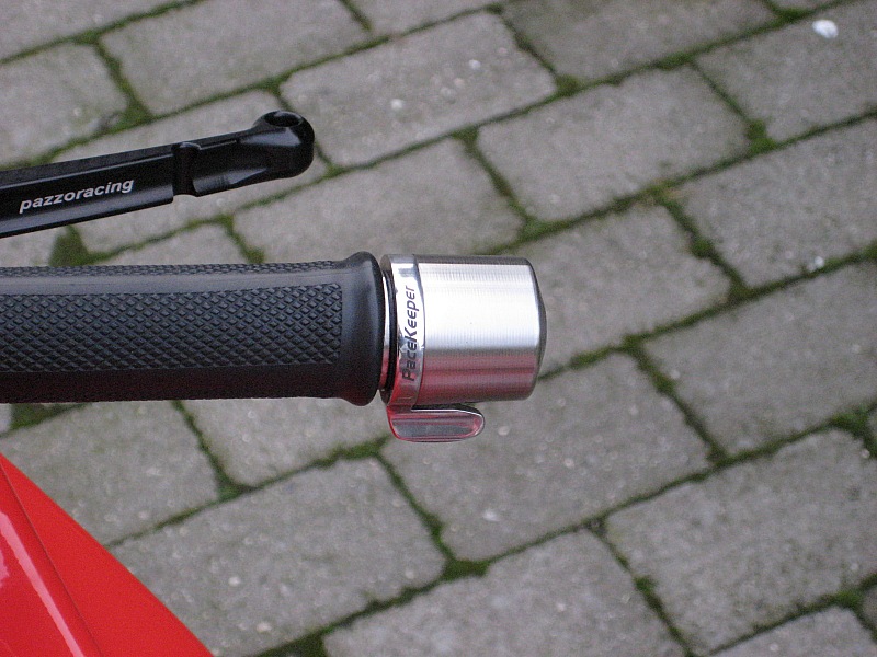
On longer trips, its nice to be able to loose your grip from the right hand bar end.
The Pacekeeper is the Danish equivalent of the well known Throttlemeister system. Its a brilliant construction that allows you to lock the throttle in any position, but it is always possible to close the throttle easily without "unlocking"
If its officially road legal, I don't know. But it is installed on every motorcycle in the Danish police force, so I'll probably never be blamed for using this fine device.
Yep, I know - its a small thing, but it's important to me.
I hate foam rubber handles! I feel like I'm losing all proper contact with my bike - Try running your own bike with only half the pressure in the tires, then you'll know what I mean. Daytona rubber grips are now installed.
Modifications (2005 - 2007) Decoration
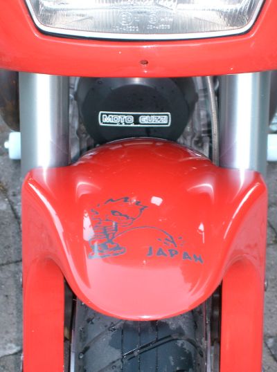
I could'nt help it, I had to......
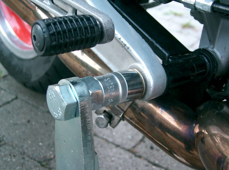
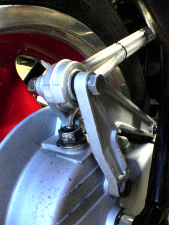
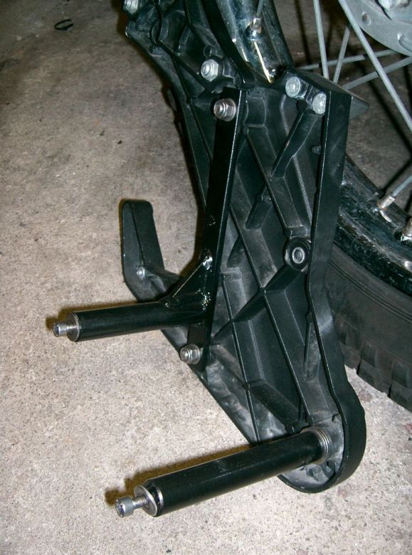
Its not easy to change tires or to lubricate the drive shaft without a center stand. I don't like the ordinary type that lifts at the rear end of the bike. It takes two people to get the bike on the stand in a safe way, and it only usable for lifting the rear end.
I found the stand in the picture at Becker Technik in Germany. It's installed on the two nuts for the rear gearbox mount, simply by using two 18mm 1/2" sockets. It works exactly like a very stable center stand. I can lift the bike on my own without the fear of dropping it, and with a block of wood under the sump it can be used when you want to work on the front end. Excellent !!
Modifications (2005 - 2007) Oil filter tool
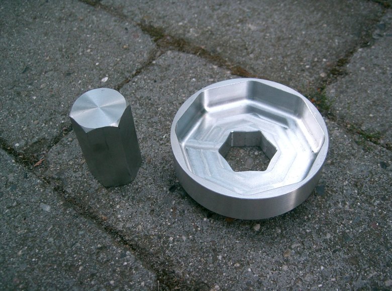
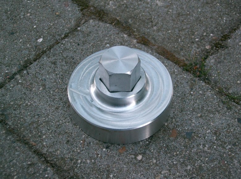
There's no standard (cheap) oil filter tool that fits the octagon shaped top of the Guzzi oil filter, and without the proper tool you can't fasten the filter correctly through the hole in sump. So to avoid lowering the sump at every oil filter change, I bought this fine tool at
Moto Spezial in Germany.
Modifications (2005 - 2007) GPS
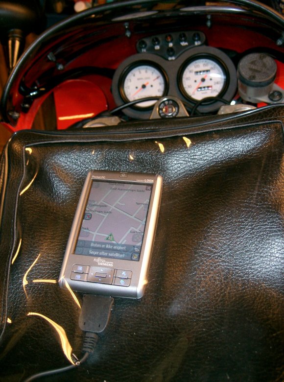
An easy project - just a detachable power supply from the battery to my PDA, which is placed in a tank bag.
Modifications (2005 - 2007) Immobilizer
Sorry - no details on this one.
(If you have to ask why, you would probably not understand the answer anyway........)
Modifications (2005 - 2007) Misc. small mods
- Cylinder head crash bars
- Aluminum exhaust flanges
- NGK red silicone spark plug caps
- CNC milled quick operation dipstick
Modifications (2008) TomTom Rider 2 GPS
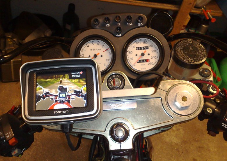
Proper motorcycle GPS's are bloody expensive, so it took a lot of belly scratching before I decided to shell out the money for a TomTom Rider 2
But it was worth every penny!
I'm not wasting any time discussing all the features of the TomTom, as this information is widely available on the net - but here are what's important to me:
- Easy and logical to use - you don't need to bring the manual.
- Fast updating on the road - you never miss a turn
- You can relax and enjoy the ride because your personal navigator makes sure you never gets lost.
The last point is the most important one . I'm not riding as much as I would like to, so when I get the possibility to go on a trip, I don't want to spend precious time finding my way.
The TomTom comes with a Bluetooth headset that went back in the box after a single test ride. I'm not having anybody telling me constantly where and when to turn when I'm on my bike.
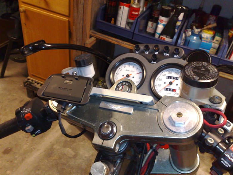
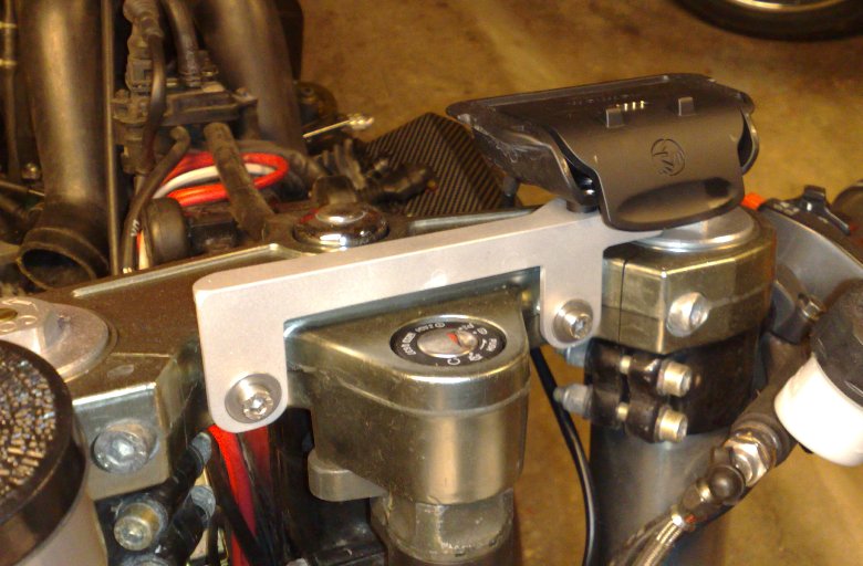
As usual, I couldn't live with the standard mounting device, so I invented yet another aluminum bracket.....
Modifications (2008) My16M Mk3 ECU
No real need for this one - the Mk1 is working flawlessly.
But I was little concerned about long term reliability of all the wires connecting the PC board with the 35 pin connector in the Mk1. So the new design of the Mk3 PC board where the 35 pin connector is soldered directly on to the PC board was the main reason to build the Mk3.
At the same time I upgraded the firmware in the Mk1 ECU to the latest version. This means that I can use the same version of maps on both units.
I'm using the Mk3 for most rides and trips, and the Mk1 for backup and testing. The original Weber Marelli ECU is just kept in the box with all the other original parts - I'll probably never use it again.
See description and pictures from the original My16M project here.
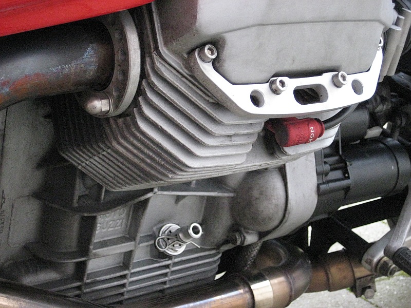
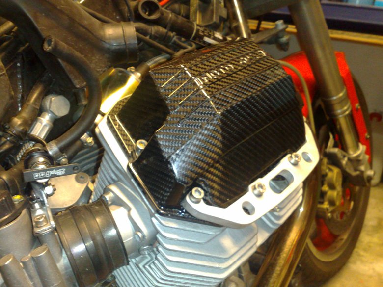
Modifications (2008) Carbon fibre valve covers
Usually, I do not add parts to my bike that have no function or is not improving some function (The sticker on my front fender have been the only exception until now)
But the opportunity to purchase a one-off set of carbon fibre valve covers was too good to miss.
I compared the new covers to the original ones on the kitchen scale, and I'm saving 150 grams per side. Absolutely neglible, but they gives a nice racing look to the bike.
Modifications (2008) Choke lever
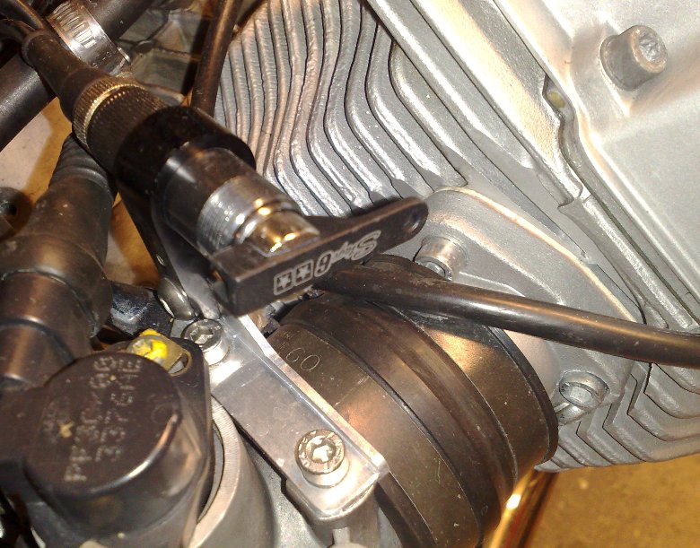
The hydraulic clutch lever unit does not leave room for the original choke lever, and after one year without the choke function, I installed a flip choke lever behind the right hand cylinder head.
Yet another aluminum bracket.......
Modifications (2008) LED rear light
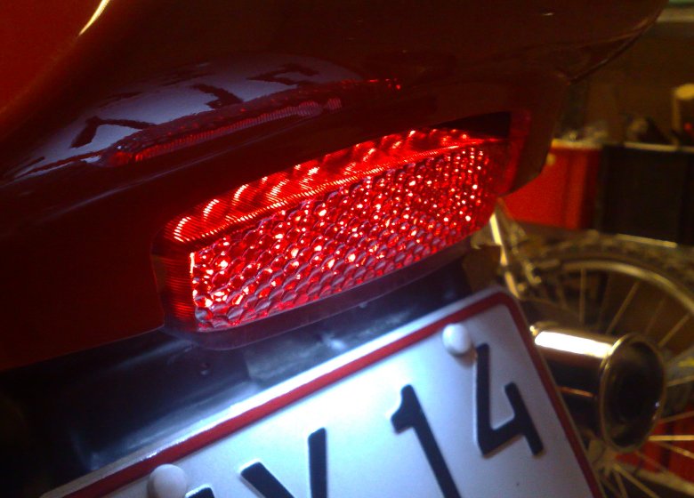
No more bulbs blown by vibration !
The rear light from a Ducati Monster fits 100%
Modifications (2008) HID Bi-Xenon head light
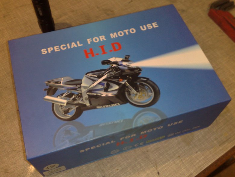
Not an easy upgrade, actually.
The xenon headlight aftermarket kit may be illegal in Denmark (nobody seems to know for sure), but I decided to install the kit anyway. You can never have enough light....
The problem with Xenon light is that you have a warm-up time of aprox. 10 seconds, so if you want a "bulb" with 2 light sources, you get Xenon low beam and an ordinary bulb for high beam light.
I went for a Bi-Xenon kit with one light source and a small solenoid moving a shield to provide high/low beam. The trade-off is that the "bulb" with the solenoid sticks 5 cm out behind the lamp, and you must have room for this.
Also, Xenon light is running on 23.000 volts, so you have to make room for the electronic black box included in the kit.
The kit was advertised as being plug-and play, so you should not have to cut any wires to connect it.
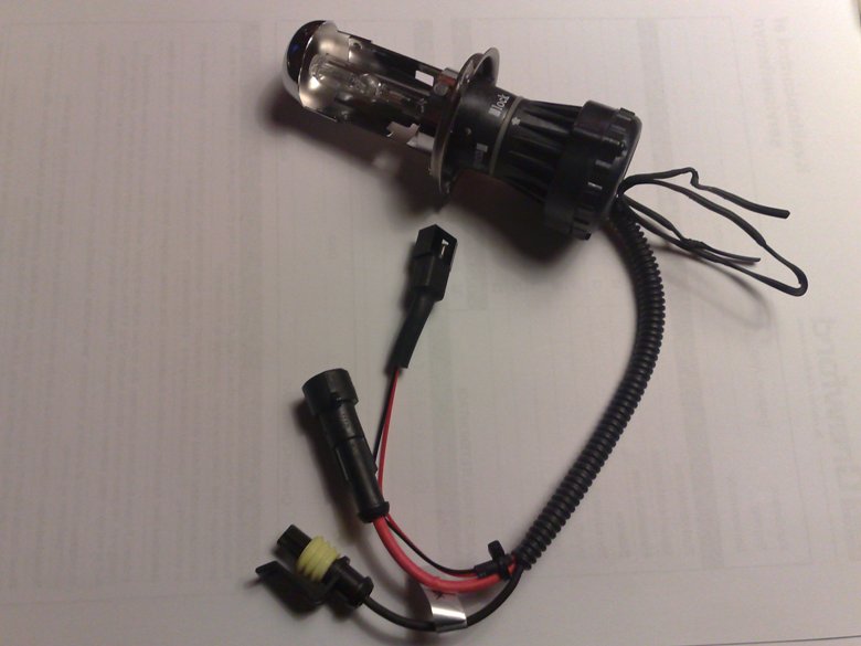
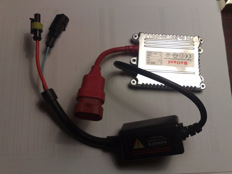
Here's the "bulb" and the electronics
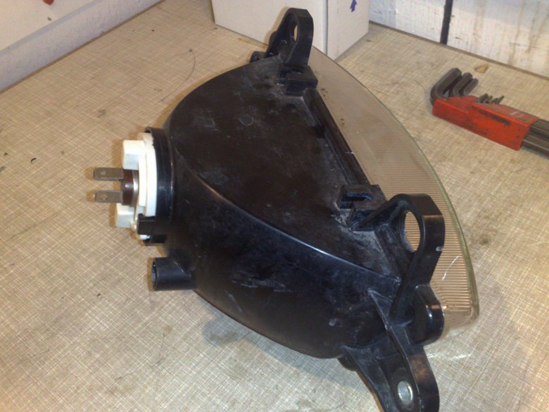
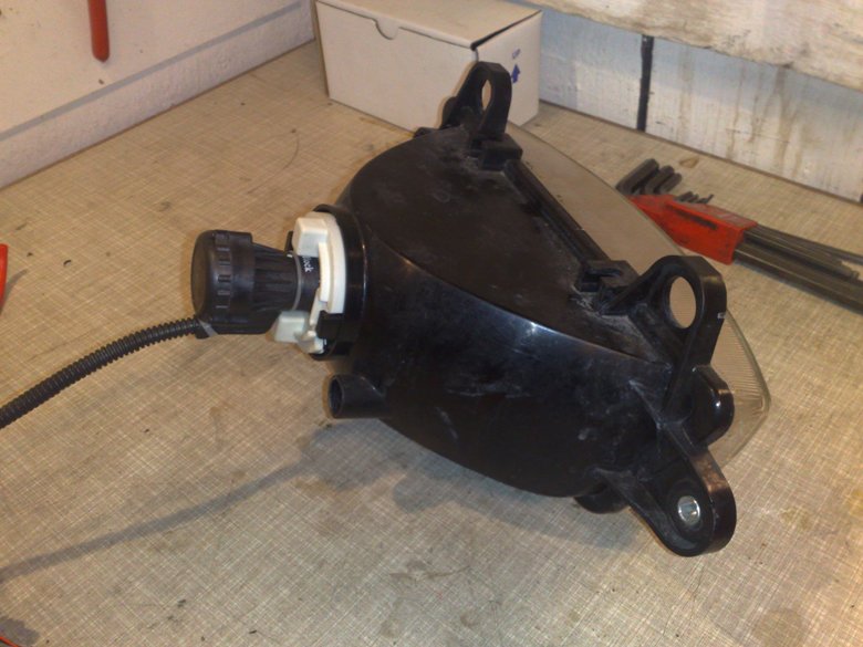
- Lamp with original 12V bulb
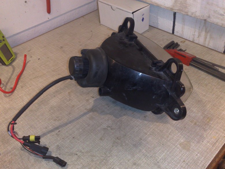
- Lamp with Xenon bulb
- Lamp with Xenon bulb and original rubber seal
It took me several hours to rearrange the wiring behind the original bulb. You may think there's plenty of room inside the fairing - Nope, its actually quite cramped in there.
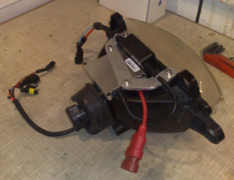
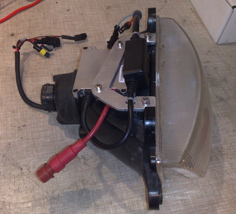
Next challenge was to place the electronics.
The only available spot was on top of the lamp. Note that the electronics is held in place by - yes - yet another aluminum bracket :-)
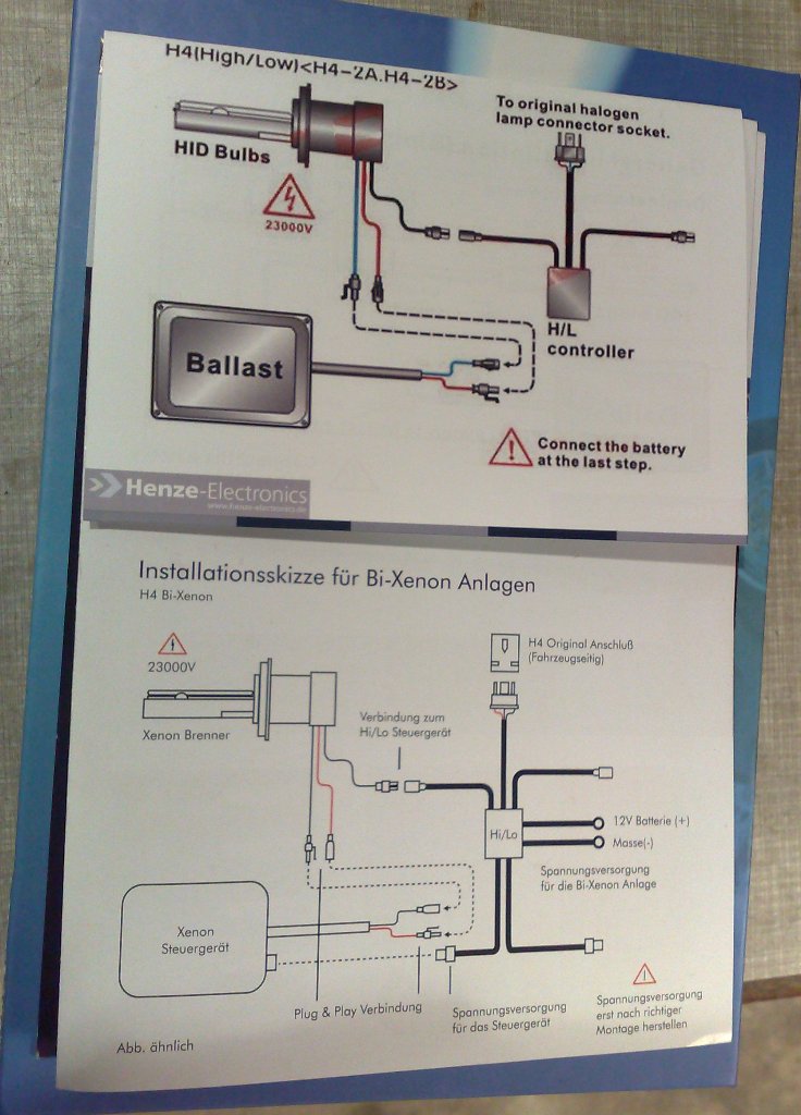
Electric connections was actually quite easy even though none of the two included drawings was 100% correct......
The only modification I had to make was to extend the pover supply cable to the battery
Modifications (2008) Inside coating of gas tank
Older gas tanks tends to rust from the inside, and the weak points always seems to be the rear lower corners where a little water is usually trapped below the gasoline.
The solution is to coat the gas tank BEFORE rust have eaten all the material - this is how you do:
- Remove all connections from the bottom of the tank - in this case it was feed, return, and gauge hardware.
- Flush the tank - if its badly rusted you may want to pour in some pebbles and water and give the tank a good shake to loosen the rust.
- Flush the tank with gasoline and dry
- Plug the holes
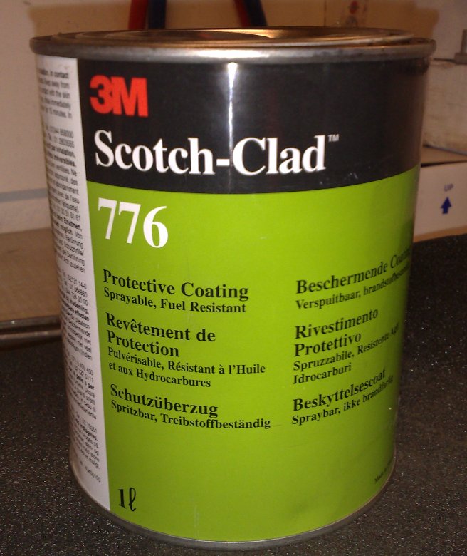
- Pour in the coating liquid (About 0,5 liter should be plenty) and turn the tank around in all directions for a few hours.
- Pull the plugs and make sure all excess coating liquid is drained
- Let dry for a few weeks.
- Reinstall hardware.
Thats it.