2013 March 19: Install the right piston and cylinder
Unbeknownest to us before we tore the engine down, Roy's 850 T3 had already been increased in displacement from 850 cc to 1000 cc. This was accomplished by using original iron lined cylinders from a later model Moto Guzzi along with Venolia pistons. We decided to re-use these components, but to have the cylinders honed and fit new rings and wrist pins. I did not have any original paperwork for the Venolia pistons. Therefore, I needed to ship the pistons to Venolia so that they could provide me with the correct rings. The first set of rings Venolia returned to me were way too small. So, I sent the rings back and Venolia sent me a much better size. Not perfect, but the best available. Aparently, these older pistons really aren't supported by Venolia anymore.
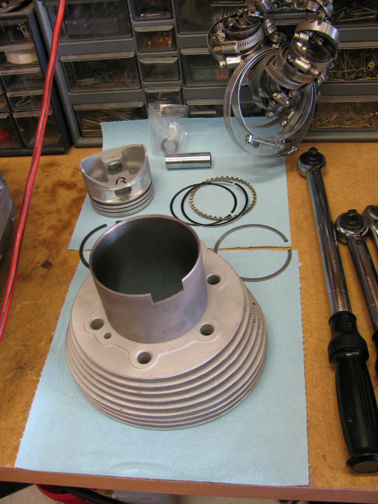
Photo courtesy of Gregory Bender.
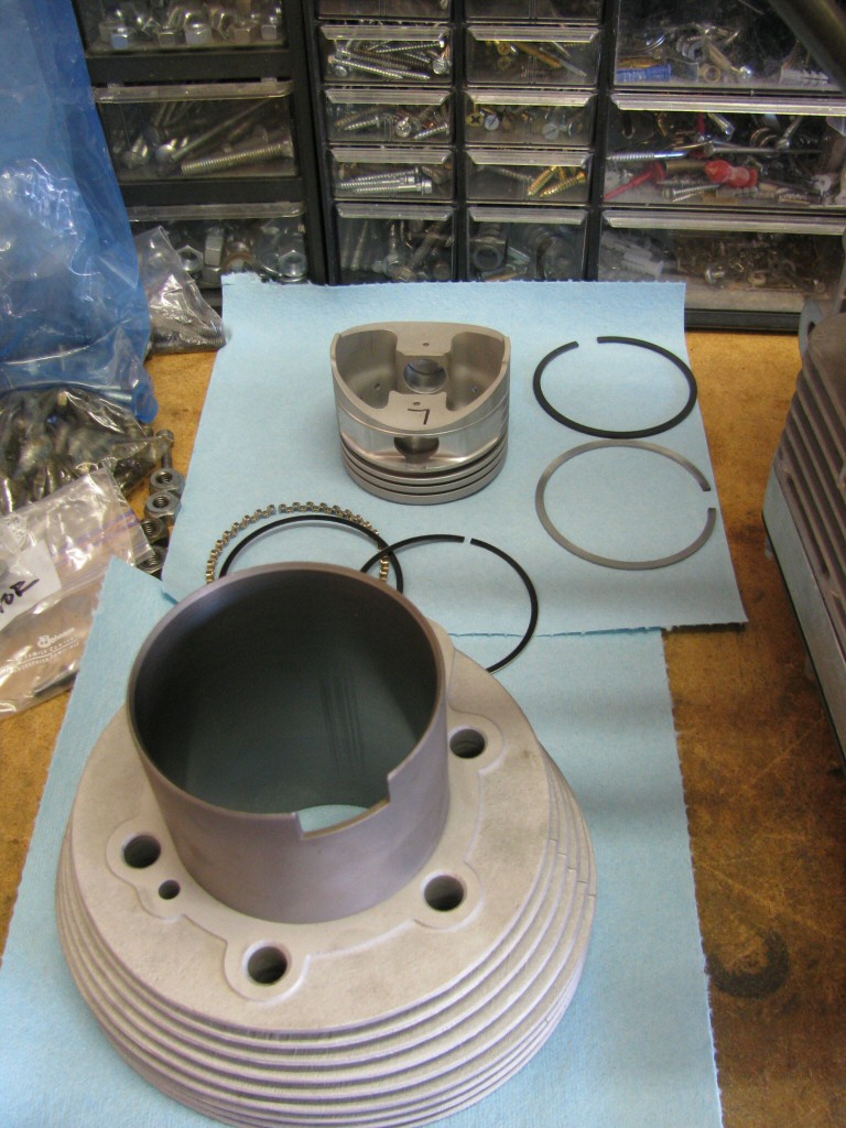
Photo courtesy of Gregory Bender.
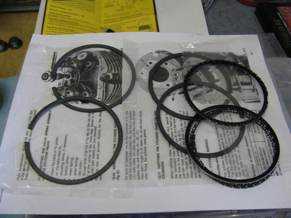
Photo courtesy of Gregory Bender.
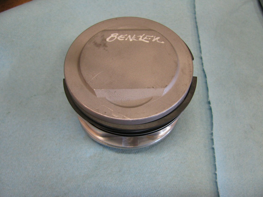
Photo courtesy of Gregory Bender.
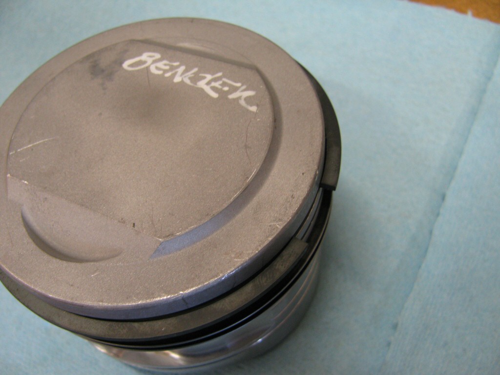
Photo courtesy of Gregory Bender.
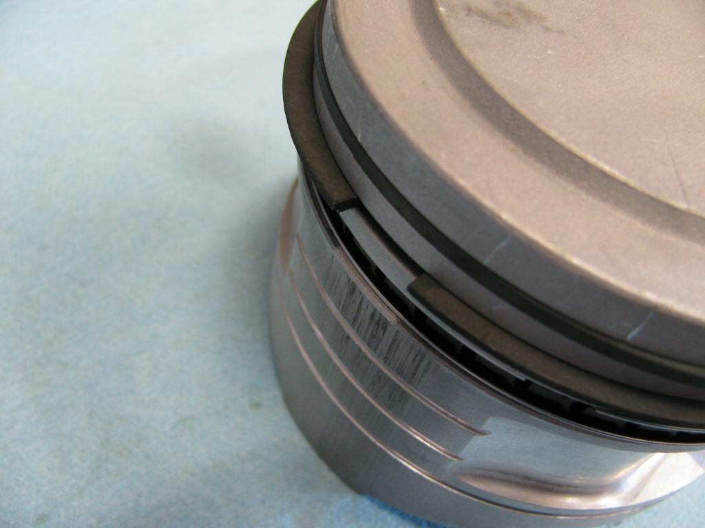
Photo courtesy of Gregory Bender.
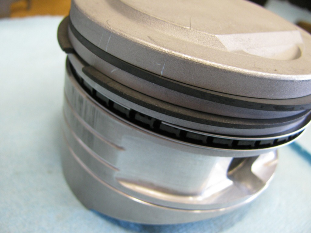
Photo courtesy of Gregory Bender.
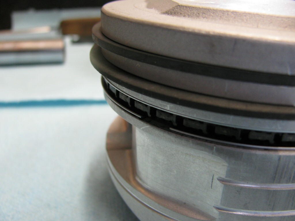
Photo courtesy of Gregory Bender.
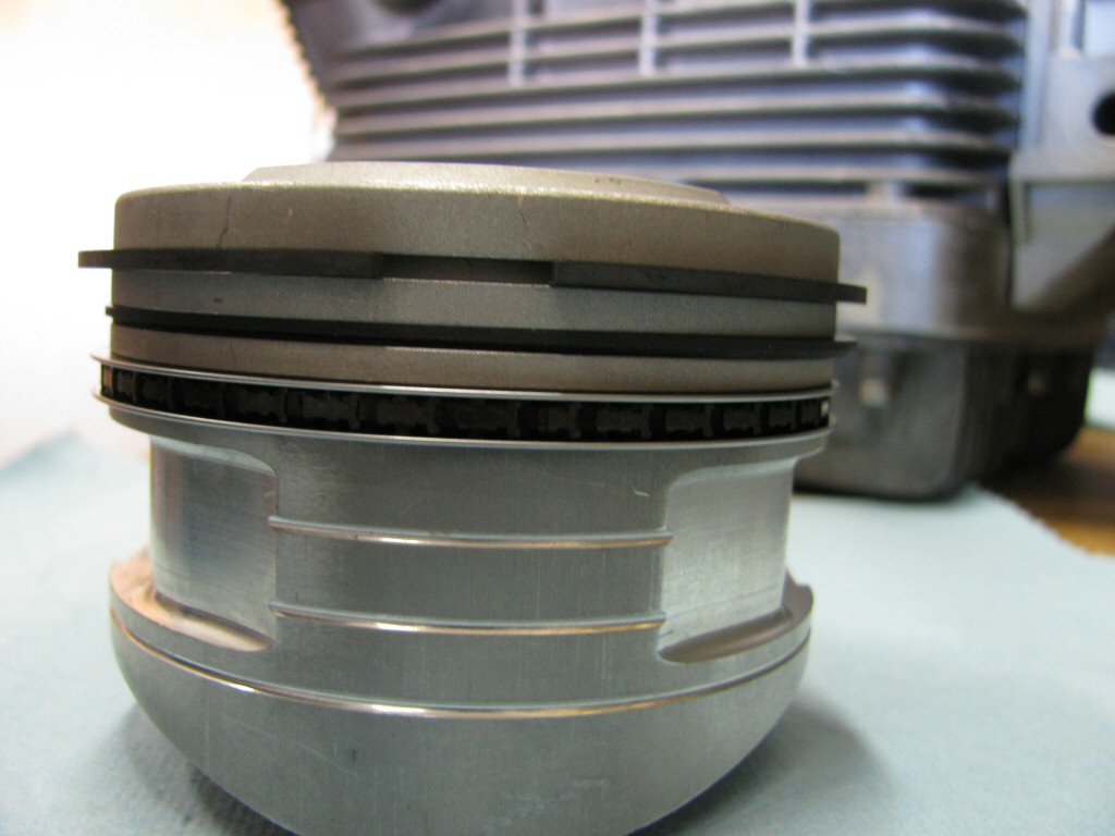
Photo courtesy of Gregory Bender.
Photo courtesy of Gregory Bender.
Photo courtesy of Gregory Bender.
Photo courtesy of Gregory Bender.
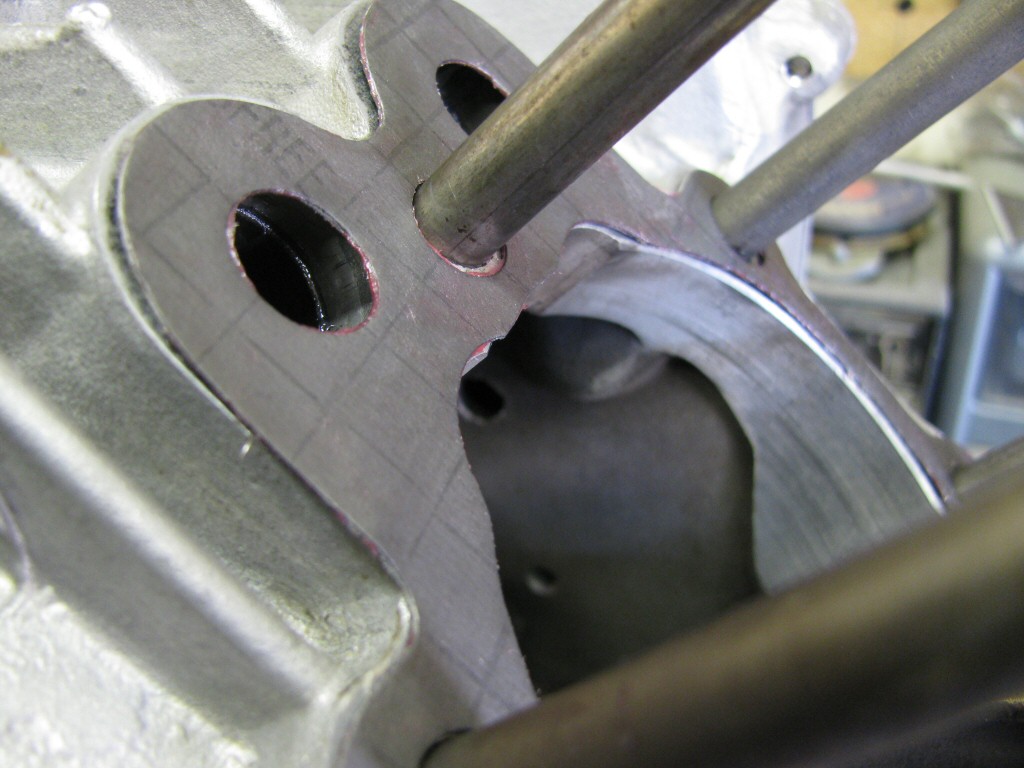
Photo courtesy of Gregory Bender.
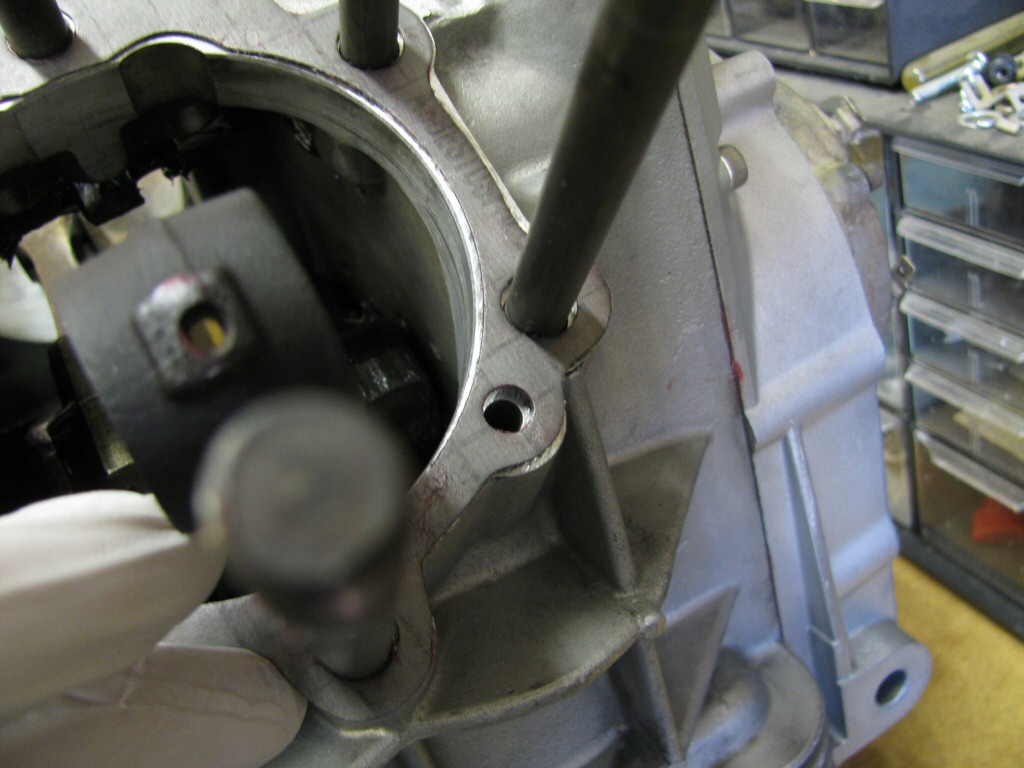
Photo courtesy of Gregory Bender.
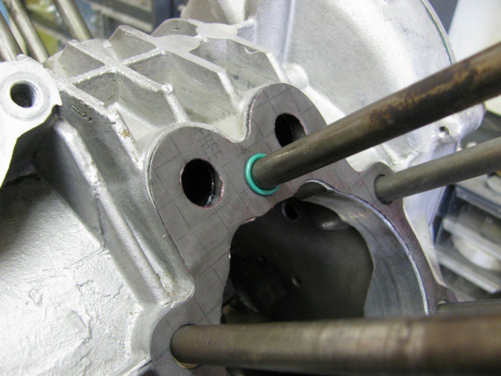
12 o'clockstud).
Photo courtesy of Gregory Bender.
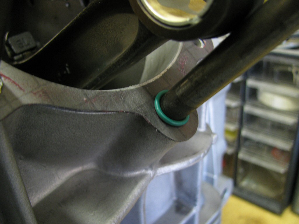
6 o'clockstud).
Photo courtesy of Gregory Bender.
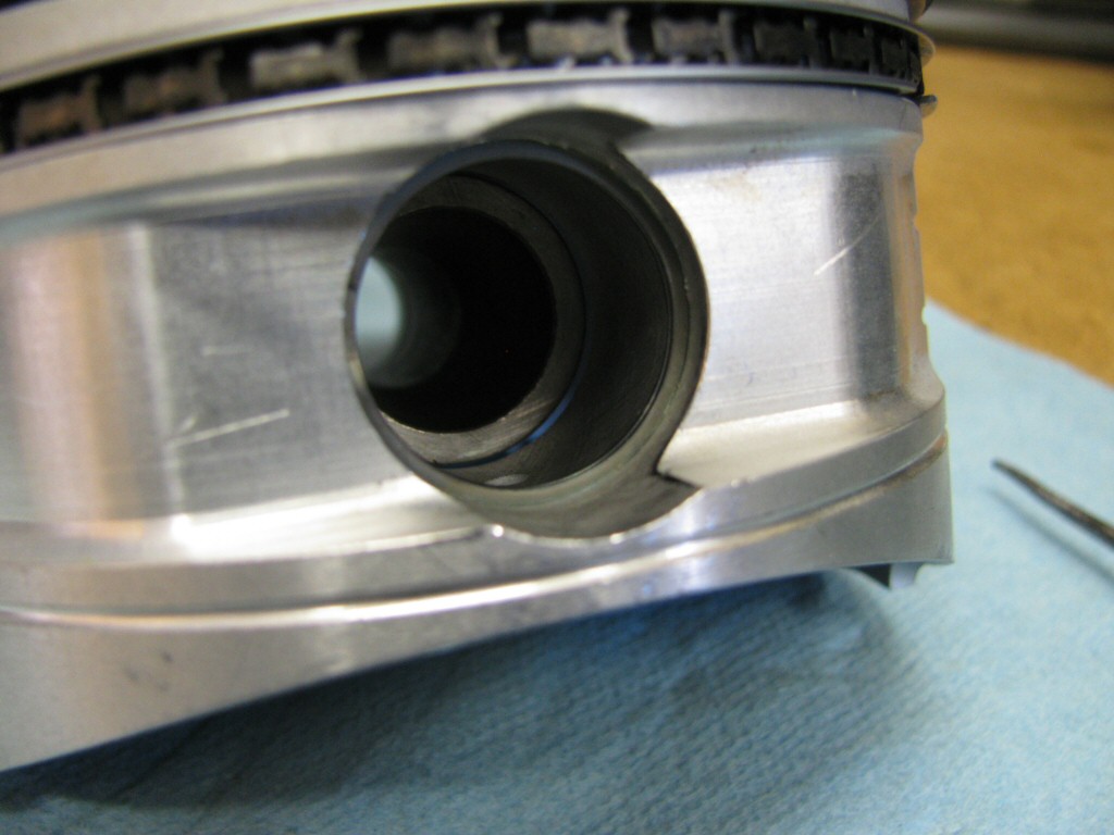
Photo courtesy of Gregory Bender.
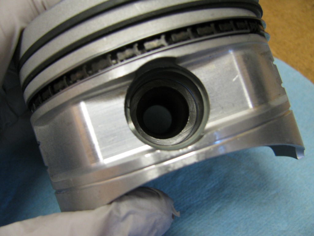
Photo courtesy of Gregory Bender.
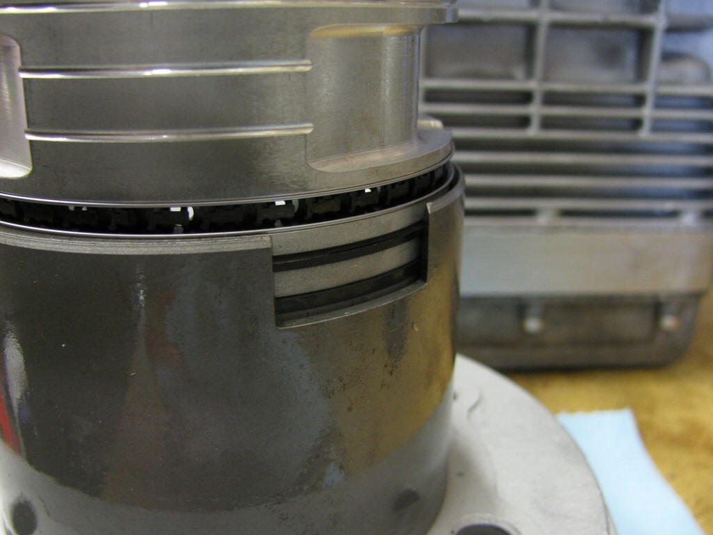
Photo courtesy of Gregory Bender.
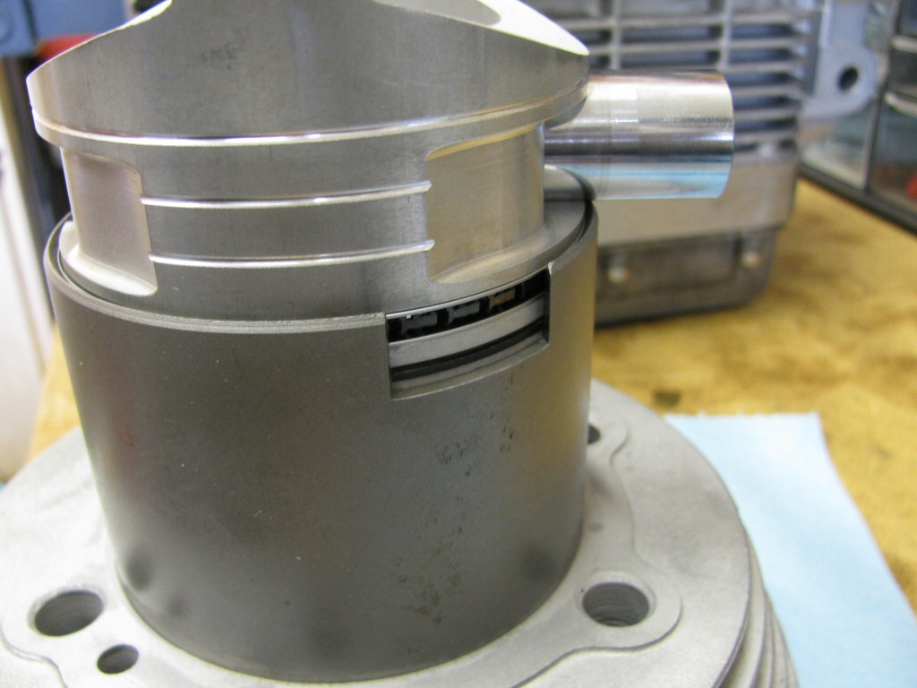
Photo courtesy of Gregory Bender.
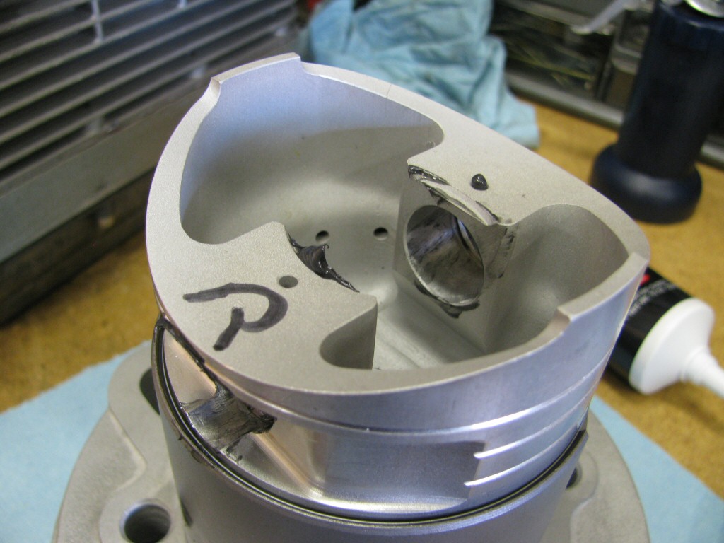
Photo courtesy of Gregory Bender.
Photo courtesy of Gregory Bender.
Photo courtesy of Gregory Bender.
Photo courtesy of Gregory Bender.
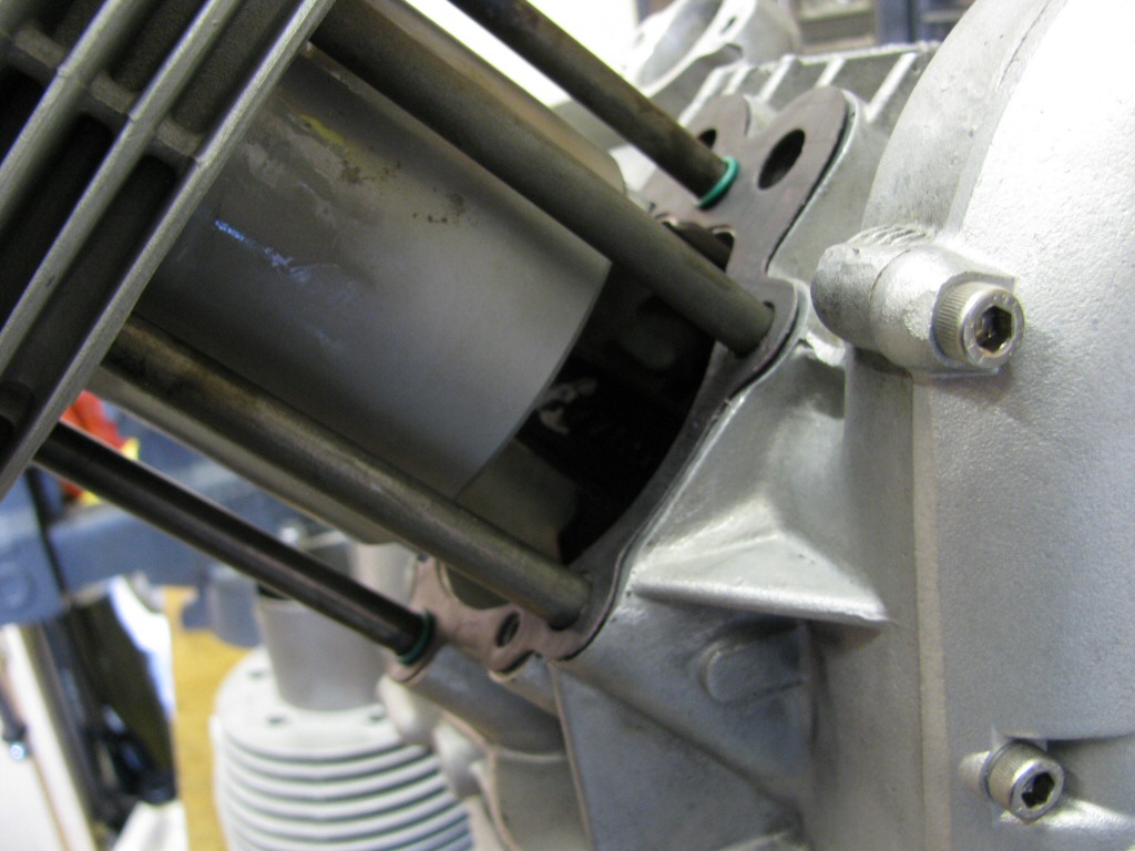
Photo courtesy of Gregory Bender.
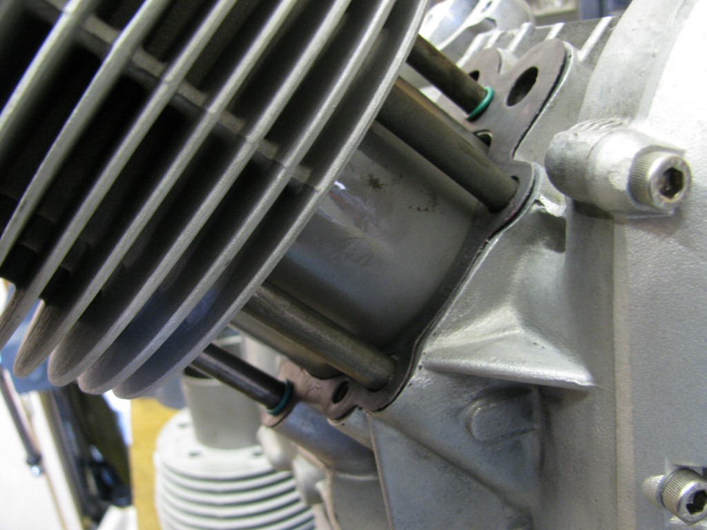
Photo courtesy of Gregory Bender.
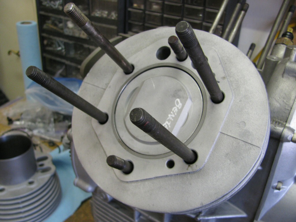
Photo courtesy of Gregory Bender.